UNIVERSITI TEKNIKAL MALAYSIA MELAKA
TO STUDY THE DEVELOPMENT OF REVERSE
ENGINEERING TECHNOLOGY THAT USING COMMON
CONSUMER ELECTRONIC DEVICE
This report is submitted in accordance with the requirement of the Universiti Teknikal Malaysia Melaka (UTeM) for the Bachelor of Manufacturing Engineering
Technology (Product Design) with Honours
by
NUR AQILAH BINTI HUSIN B071310573
940107-04-5146
UNIVERSITI TEKNIKAL MALAYSIA MELAKA
BORANG PENGESAHAN STATUS LAPORAN PROJEK SARJANA MUDA
TAJUK: To Study The Development Of Reverse Engineering Technology That Using Common Consumer Electronic Device
SESI PENGAJIAN: 2016/2017 Semester 1
Saya NUR AQILAH BINTI HUSIN
mengaku membenarkan Laporan PSM ini disimpan di Perpustakaan Universiti Teknikal Malaysia Melaka (UTeM) dengan syarat-syarat kegunaan seperti berikut:
1. Laporan PSM adalah hak milik Universiti Teknikal Malaysia Melaka dan penulis. 2. Perpustakaan Universiti Teknikal Malaysia Melaka dibenarkan membuat salinan
untuk tujuan pengajian sahaja dengan izin penulis.
3. Perpustakaan dibenarkan membuat salinan laporan PSM ini sebagai bahan pertukaran antara institusi pengajian tinggi.
4. **Sila tandakan ( )
SULIT
TERHAD
TIDAK TERHAD
__________________________
Alamat Tetap:
373-10 Batu 3, Balai Panjang,
75250 Melaka.
Tarikh: ________________________
Disahkan oleh:
Cop Rasmi:
Tarikh: _______________________
** Jika Laporan PSM ini SULIT atau TERHAD, sila lampirkan surat daripada pihak berkuasa/organisasi berkenaan dengan menyatakan sekali sebab dan tempoh laporan PSM ini perlu dikelaskan sebagai SULIT atau TERHAD.
(Mengandungi maklumat yang berdarjah keselamatan atau kepentingan Malaysia sebagaimana yang termaktub dalam AKTA RAHSIA RASMI 1972)
i
DECLARATION
I hereby, declared this report entitled “To Study The Development Of Reverse Engineering Technology That Using Common Consumer Electronic Device” is the
results of my own research except as cited in references.
Signature : ……….
Author’s Name : NUR AQILAH BINTI HUSIN
ii
APPROVAL
This report is submitted to the Faculty of Engineering Technology of UTeM as a partial fulfilment of the requirements for the degree of Bachelor of Manufacturing Engineering Technology (Product Design) with Honours. The member of the supervisory is as follow:
………. ENCIK MOHD QADAFIE BIN IBRAHIM
iii
ABSTRAK
iv
ABSTRACT
v
DEDICATION
vi
ACKNOWLEDGEMENT
Alhamdulillah, I am grateful and would like to express my gratitude and appreciation to my supervisor, Encik Mohd Qadafie Bin Ibrahim for all invaluable guidance, suggestions, encouragement and also constant support through the research period and contribution to make this project success. I appreciate his guidance starting from the beginning to the final level of this project which enable me to develop a better understanding for this project.
I also would like to express a very special thanks to Encik Zulkifli the technician at Rapid Manufacturing laboratory in department of Manufacturing Engineering Technology for his cooperation and assistance about the equipment in the laboratory for my research study. Furthermore, not forget to every assistant engineer in Faculty of Engineering Technology (FTK) in UTeM for their cooperation.
I also would like to give my deepest gratitude and special thanks to my beloved parents, Husin Bin Abd. Rahman and Rohani Binti Aman for their love, dream and sacrifice throughout my life. I could not find any other appropriate words that could describe my thankfulness to them for their devotion, support and faith in me to achieve my dreams.
Lastly, I would like to thanks every person that contributes to my final year project by directly or indirectly ways. I appreciated all the suggestions and comments throughout this project.
vii
TABLE OF CONTENT
Declaration i
Approval ii
Abstrak iii
Abstract iv
Dedication v
Acknowledgement vi
Table of Content viii
List of Tables x
List of Figures xii
List of Abbreviations, Symbols and Nomenclatures xiv
CHAPTER 1: INTRODUCTION 1
Introduction 1
1.1 Background 1
1.2 Problem Statement 2
1.3 Objectives 2
1.4 Work Of Scope 3
CHAPTER 2:LITERATURE REVIEW 4
Introduction 4
2.1 Photogrammetry 4
2.1.1 Types Of Photogrammetry 7
2.1.2 Photogrammetry Mechanisms 7
2.2 Photogrammetry and Photometry 8
2.2.1 Photometry Application 9
2.2.2 Photogrammetry Application 9
2.2.3 Photometry Equipment 11
2.3 Photogrammetry Equipment 12
2.3.1 Photogrammetry Software 12
viii
2.3.3 Set up Equipment 17
CHAPTER 3:METHODOLOGY 23
Introduction 23
3.1 Flow of the Process 23
3.2 The Hardware 25
3.3 Photogrammetry Software 27
3.3.1 Software Analysis 27
3.3.2 Pre-processing Software 28
3.3.3 Post-processing Software 30
3.4 Subject Selection 30
3.5 Setup Equipment Methods 31
3.6 The Professional Scanning Methods 34
CHAPTER 4:RESULTS AND DISCUSSIONS 37
Introduction 37
4.1 Results 37
4.1.1 3D Processing Raw Data 37
4.1.2 Final Data 40
4.1.3 3D Printed Model 42
4.2 Discussions 43
4.2.1 3D Data Editing 43
4.2.2 Deviation 45
4.2.3 Physical Features 47
4.2.4 Dimensions 50
CHAPTER 5:CONCLUSION AND RECOMMENDATION 54
Introduction 54
5.1 Conclusion 54
5.2 Recommendation 55
ix
APPENDICES 59
A Project Planning 59
B Meshmixer’s Software Manual 61
C Geomagic Studio Software Tutorial 74
x
LIST OF TABLES
Table 3.1 Specification of Huawei Nexus 6P smartphone. 25 Table 3.2 The Pugh Table of the Photogrammetry 27
3D Scanning Software.
Table 3.3 Specification of the REXCAN CS2+. 36
Table 4.1 Statistic of the Deviation Result. 46 Table 4.2 The Dimensions Results of the Point to Point 51
of the models.
Table 4.3 The value calculated of the percentage differences. 52 Table 4.4 The value calculated for each model of the dimensions. 53 Table 4.5 Percentage value of the comparison between the Rexcan 53
xi
[image:13.595.105.521.122.769.2]LIST OF FIGURES
Figure 2.1 Picture of Output of Photogrammetry used for Map taken 5 for Aircraft.
Figure 2.2 Picture of Photogrammetry used for Drawing. 5 Figure 2.3 Picture of Photogrammetry used for Measurement. 6 Figure 2.4 Photogrammetry used for 3D reconstruction. 6 Figure 2.5 The distances and angles between imagers and the 8
projected light source create a base of triangle.
Figure 2.6 A schematic of the triangulation technique to show the 8 location of a point.
Figure 2.7 Show a Physical Original Model (A) and the Digital 10 3D Model.
Figure 2.8 Show the Deviation Results of the 3D Data 10 Compared with PhotoScan.
Figure 2.9 Show the deviation results of the 3D data compared 11 with 123D Catch.
Figure 2.10 The set up equipment of photometry. 12 Figure 2.11 Photomodeler of Architecture shots and 3D viewing. 14 Figure 2.12 Interface of process capturing picture by using 15
Autodeks’s123D Catch on mobile phone.
Figure 2.13 Interface of process transmitting the pictures into 15 3D model and the 3D model in the mobile phone.
Figure 2.14 Interface of process transmitting the pictures into 16 3D model and the 3D model in the mobile phone.
Figure 2.15 Setup Equipment for Walk around Method. 18
Figure 2.16 The Walk Around Method. 18
Figure 2.17 Setup Equipment for the Turntable Method. 19
Figure 2.18 The Turntable Method. 19
Figure 2.19 Set up Equipment of Method Open Room Set up. 20 Figure 2.20 Position image of the multi camera of the clay. 21
xii Figure 2.22 The Green Chroma Key backdrop with 22
the open-sided light tents.
Figure 3.1 Flow Process of the Project. 24 Figure 3.2 The Huawei Nexus 6P Smartphone. 26 Figure 3.3 The ProJet CJP 460PLUS Rapid Prototyping (RP) 26
machine.
Figure 3.4 Picture of the interface of the process 29 reconstruction on the SCANN3D software.
Figure 3.5 The 3D model data on the interface of 29 the SCANN3D.
Figure 3.6 Actual Model Of Porcelain Cat. 30 Figure 3.7 The Set Up Equipment of the SCANN3D 32
software method.
Figure 3.8 The Set Up Equipment of the SCANN3D 32 software method.
Figure 3.9 The Interface of the Scanning Process of the 33 SCANN3D Software.
Figure 3.10 The Interface of the Calculation Process. 33
Figure 3.11 The REXCAN CS2+ Scanner. 35
Figure 3.12 The Calibration Process of Rexcan Scanner. 36
Figure 4.1 The Set of Images Process Data of the Cat 38 by Using SCANN3D Software.
Figure 4.2 The OBJ file 3D data by the SCANN3D software. 38 Figure 4.3 The Set of Images Process Data of the Cat 39
by Using REXCAN Scanner.
[image:14.595.110.517.70.789.2]Figure 4.4 The STL file 3D Data Model of the Rexcan Scanner. 40 Figure 4.5 Final 3D data of SCANN3D software. 41 Figure 4.6 Final 3D data of Rexcan scanner. 41 Figure 4.7 3D Printer Projet CJP 460Plus. 42 Figure 4.8 3D Printed Model from the Rexcan Scanner (left) 43
and SCANN3D Software (right).
xiii Figure 4.10 The STL 3D Data of Rexcan Scanner. 45 Figure 4.11 The Deviation results between the 3D data 46
of the Scann3d software and Rexcan scanner.
Figure 4.12 The Actual Porcelain Cat (left), Rexcan’s 3D Printed 48 Model (middle) and SCANN3D’s Printed Model
(left) of the actual cat.
Figure 4.13 The head feature comparison of the actual cat (left), 48 Rexcan (middle), SCANN3D (right).
Figure 4.14 The tail feature comparison of the actual cat (left), 48 Rexcan (middle), SCANN3D (right).
Figure 4.15 The leg feature comparison of the actual cat (left), 49 Rexcan (middle), SCANN3D (right).
xiv
LIST OF ABBREVIATIONS, SYMBOLS AND
NOMENCLATURES
CAD - Computer Aided Design
3D - 3Dimensional
2D - 2Dimenional
CT - Computed Tomography
CMM - Coordinate Measuring Machines DEM - Digital Elevation Model
BAE - British Aerospace
SOCETSET - SOftCopy Exploitation Toolkit EOS - Electronic Operating System STL - Stereo Lithography
OBJ - Wave front
PLY - Polygon File Format
VRML - Virtual Reality Modelling Language DSLR - Digital Single Lens Reflex
Mm - Millimetre MP - Megapixel
OS - Operating System
IOS - IPhone operating System FOV - Field of View
xv CJP - ColorJet Printing
CCD - Charge-coupled Device USB - Universal Serial Bus LED - Light-emitting Diode
1
CHAPTER 1
INTRODUCTION
Introduction
In this chapter it will show about the background of the project title which is about the Reverse Engineering (RE) technology. It will also show the problem statement, objective and work of scope of this project.
1.1 Background
The development of Reverse Engineering technology has been increases significantly throughout the years. Reverse engineering (RE) is the process that build a copy of existing products into a 3D model CAD data to duplicating it or make improvement to it. It is a process without using the engineering drawing but other technique such as scanning or digitizing to get the CAD model. There are two types of engineering, which is the reverse engineering and another type is the forward engineering. Forward engineering is different compare with the reverse engineering because it is a normal process from a high-level abstractions and logical designs that use engineering drawing to implement to a physical of a system. Some definitions of RE by researcher RE is the process of retrieving new geometry from a manufactured part by digitizing and modifying an existing CAD model (Yau Hong Tzong, et al., 1993).
2 This project is to study about the development of reverse engineering technology. The particular technology is the photogrammetry 3D scanning. Photogrammetry is the science of making measurements from photograph. By using the principle of photogrammetry in 3D scanning it can produce a real physically 3D model objects from a set of photos. The study will be focus on the photogrammetry software by using common electronic device such as smartphone and computer. The scope of the project is to investigate the software and finding the best solution to do 3D scanning and 3D reconstruction for public users.
1.2 Problem Statement
Some of 3D scanning methods required high cost to conduct it. Before this, to do 3D scanning, they need to build a high cost scanning system such as the traditional photogrammetry which need to build with many camera and lighting system. Besides that, some people might face difficulty to use 3D scanning because it need an expert to operate it. Furthermore, it might require special training to do the 3D scanning methods.
1.3 Objectives
1) To study about the 3D scanning photogrammetry software that available in market.
2) To determine the optimum methods on how to use 3D photogrammetric software to generate 3D data.
3
1.4 Work Of Scope
4
CHAPTER 2
LITERATURE REVIEW
Introduction
In literature review it will discussed about the researches related to the project title which is “To Study the Development of Reverse Engineering Technology That Using Common Consumer Electronic Device”. It will continuously carried throughout this project to study about the past and current research work related to project title. The RE technology that has been chosen is the photogrammetry 3D scanning technology which some of important issues and data of it have to be studied, reviewed, determined and applied for this project.
2.1 Photogrammetry
5 object or scene or more known as 3D reconstruction (Figure 2.4). (Alan Walford, 2007)
Figure 2.1 Picture of Output of Photogrammetry used for Map taken for Aircraft. (Mike Foster, 2016)
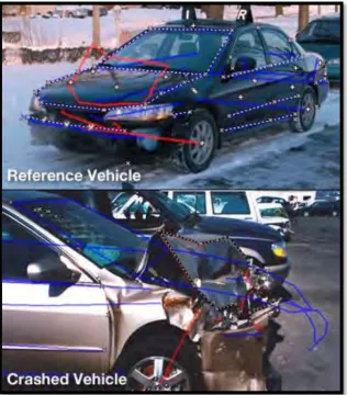
[image:22.595.159.484.338.603.2]6 Figure 2.3 Picture of Photogrammetry used for Measurement. (Crashteams, 2008)
[image:23.595.173.509.480.654.2]7 to create a photogrammetry program that exclusively for mobile phone other than for desktop used. This is because mobile phone has become more advanced and the resolution of the camera has increased which comparable with digital camera these days.
2.1.1 Types Of Photogrammetry
There are two types of photogrammetry which is the aerial photogrammetry and the close-range photogrammetry. Aerial photogrammetry use camera which is mounted to the aircraft and usually it is pointed vertically towards the ground to capture the scene. The processed picture is in a stereo-plotter which it act as instrument that lets an operator see two pictures at once. It is used in automated processing for Digital Elevation Model (DEM) creation which is the digital model of a terrain’s surface such as planet, moon and asteroid. There are several types of software for aerial photogrammetry such as the BAE system SOCETSET, DAT/EM International Summit Evolution, Intergraph 2/1 Imaging, KLT Associates ATLAS and PCI Geomatics.
Another type of photogrammetry is the closed-range photogrammetry which use camera by hand-held or tripod to it close to the subject that need to be taken. It is also known as Image-Based Modeling. Some examples of the software are EOS System PhotoModeler (Full-Capability Close-Range Photogrammetry), GSI V-stars (High Accuracy Industrial Measurement Photogrammetry), and also Autodesk 123D Catch; PhotoModeler Scanner; Acute 3D (Textured 3D Model Extraction). (Alan Walford, 2007)
2.1.2 Photogrammetry Mechanisms