Appendix 3: Test Cells Construction Journal
The Empirical Validation of House Energy Rating
(HER) Software for Lightweight Housing in Cool
Temperate Climates
Mark Dewsbury
B Arch, B Env. Design, Grad. Cert. Management
Submitted in total fulfilment of the requirements of the degree of Doctor of Philosophy
September 2011
!
School of Architecture & Design
TABLE of CONTENTS
TABLE of CONTENTS ... 1
LIST of FIGURES ... 2
3.1. Introduction ... 10
3.2. Construction Journal ... 10
June 5, 2006 ... 11
June 6, 2006 ... 11
June 7, 2006 ... 12
June 8, 2006 ... 14
June 9 to 12, 2006 ... 16
June 13, 2006 ... 17
June 14, 2006 ... 20
June 15, 2006 ... 21
June 16, 2006 ... 22
June 19, 2006 ... 24
June 20, 2006 ... 25
June 21, 2006 ... 27
June 22 to 23, 2006 ... 28
June 26, 2006 ... 29
June 27, 2006 ... 32
June 28, 2006 ... 32
June 29, 2006 ... 35
June 30, 2006 ... 36
July 3, 2006 ... 40
July 4, 2006 ... 44
July 5, 2006 ... 46
July 6, 2006 ... 49
July 7, 2006 ... 53
July 8, 2006 ... 54
July 10, 2006 ... 56
July 11, 2006 ... 58
July 12 to August 23, 2006 ... 59
LIST of FIGURES
Figure A3.1 - Erection of safety exclusion fence (June 5, 2006) ... 11
Figure A3.2 - First profiles erected for site set-out of the test cells (June 5, 2006) ... 11
Figure A3.3 - Test cell site photograph (June 6, 2006) ... 12
Figure A3.4 - Site scraping for the concrete slab-on-ground floored test cell (June 6, 2006) . 12 Figure A3.5 - Excavator at work on enclosed-perimeter platform-floored test cell (June 7) .. 13
Figure A3.6 - Excavation for footings and pole supports of the unenclosed-perimeter platform-floored test cell (June 7) ... 13
Figure A3.7 - Trench for strip footings, pole holes and below-ground temperature probe hole for the enclosed-perimeter platform-floored test cell (June 7) ... 13
Figure A3.8 - Trench for strip footings and below-ground temperature probe hole for the concrete slab-on-ground floored test cell (June 7) ... 13
Figure A3.9 - Excavation of hole for below-ground temperature probe (June 7, 2006) ... 14
Figure A3.10 - Hole for below-ground temperature probe (June 7, 2006) ... 14
Figure A3.11 - Unenclosed-perimeter platform-floored test cell (June 8, 2006) ... 15
Figure A3.12 - Unenclosed-perimeter platform-floored test cell: detail of pole supports (June 8, 2006) ... 15
Figure A3.13 - Enclosed-perimeter platform-floored test cell with pole and pole supports in place (June 8, 2006) ... 15
Figure A3.14 - Concrete slab-on-ground floored test cell (June 8, 2006) ... 15
Figure A3.15 - Insertion of PVC sleeve for below-ground temperature measurement (June 8, 2006) ... 16
Figure A3.16 - PVC sleeve capped prior to back-filling (June 8, 2006) ... 16
Figure A3.17 - PVC sleeve for below-ground temperature probe backfilled: Unenclosed-perimeter platform-floored test cell (June 8, 2006) ... 16
Figure A3.18 - PVC sleeve for below-ground temperature probe backfilled: Concrete slab-on-ground floored test cell (June 8, 2006) ... 16
Figure A3.19 - Site photograph (June 13, 2006) ... 17
Figure A3.20 - Pre-fabricated wall trusses delivered to site (June 13, 2006) ... 17
3.1.
Introduction
The construction of the three test cells commenced on June 5, 2006, and an official opening which signified the completion of the construction stage of the test cells was held on August 23, 2006. The design of the test cells and other matters pertaining to their construction are discussed in Section 4.2. Like any construction project, the works were subject to contractor availability and the vagaries of weather. As a result, several construction days were lost due to consistent rain and a strong storm on the weekend of July 1 removed the building wrap, which had been carefully installed in the days before.
To best illustrate the construction process of the three Test Cells, a condensed version of events detailing key events from each day, with supporting images, is shown in the following pages. This is shown to inform other software users of the construction methods and detailing relevant to Australian residential construction practice, which is of great importance when providing inputs for detailed simulations (Agami Reddy, Maor & Panjapornpon 2007; Lomas 1994; LomasEppel et al. 1994; LomasMartin et al. 1994).
3.2.
Construction Journal
June 5, 2006
Weather: fine
Trades on Site: carpenters
This was the first official day of work on site by the builder. The primary tasks of the day included the erection of a safety exclusion fence and commencement of set-out guides for each test cell. All set-out guides used the True North survey markers as reference points.
Figure A3.1 - Erection of safety exclusion fence (June 5, 2006)
Figure A3.2 - First profiles erected for site set-out of the test cells (June 5, 2006)
June 6, 2006
Weather: fine
Trades on site: carpenters, excavator contractor
Figure A3.3 - Test cell site photograph (June 6, 2006)
Figure A3.4 - Site scraping for the concrete slab-on-ground floored test cell (June 6, 2006)
June 7, 2006
Weather: fine
Trades on site: carpenters, excavator contractor
Unenclosed-perimeter platform- floored test cell
- Excavation of holes for the footings and pole supports
Enclosed-perimeter platform- floored test cell
- Excavation of strip footings and holes for pole supports
Concrete slab-on-ground floored test cell
- Site levelling and excavation of strip footings
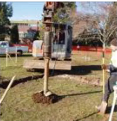
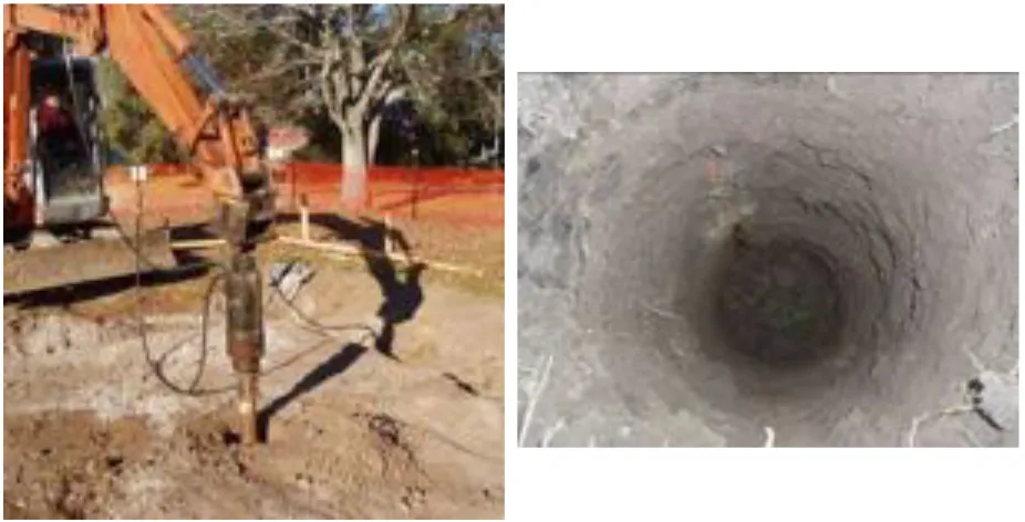
Excavation of a 1200mm hole in the centre of each test cell for the future installation of below ground (-1000mm) temperature probes
Figure A3.5 - Excavator at work on enclosed-perimeter platform-floored test cell (June 7)
Figure A3.6 - Excavation for footings and pole supports of the unenclosed-perimeter
platform-floored test cell (June 7)
Figure A3.7 - Trench for strip footings, pole holes and below-ground temperature probe hole for the enclosed-perimeter platform-floored test cell
(June 7)
Figure A3.8 - Trench for strip footings and below-ground temperature probe hole for the concrete
Figure A3.9 - Excavation of hole for below-ground temperature probe (June 7, 2006)
Figure A3.10 - Hole for below-ground temperature probe (June 7, 2006)
June 8, 2006
Weather: fine
Trades on site: carpenters, excavator contractor
Unenclosed-perimeter platform-floored test cell
- Formwork for pole footings installed and poles dropped in to holes.
Enclosed-perimeter platform-floored test cell - Formwork for pole footings installed
Concrete slab-on-ground floored test cell
- Site set out reconfigured to suit slab formwork preparation
Figure A3.11 - Unenclosed-perimeter platform-floored test cell (June 8, 2006)
Figure A3.12 - Unenclosed-perimeter platform-floored test cell: detail of pole supports (June 8,
2006)
Figure A3.13 - Enclosed-perimeter platform-floored test cell with pole and pole supports in place (June
8, 2006)
Figure A3.15 - Insertion of PVC sleeve for
below-ground temperature measurement (June 8, 2006) Figure A3.16 - PVC sleeve capped prior to back-filling (June 8, 2006)
Figure A3.17 - PVC sleeve for below-ground temperature probe backfilled: Unenclosed-perimeter platform-floored test cell (June 8, 2006)
Figure A3.18 - PVC sleeve for below-ground temperature probe backfilled: Concrete
slab-on-ground floored test cell (June 8, 2006)
June 9 to 12, 2006
June 13, 2006
Weather: fine/cloudy
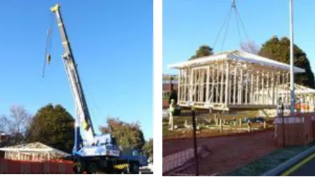
Trades on site: carpenters, excavator contractor, electricians, plumbers, crane driver (for unloading trusses and wall frames)
Unenclosed-perimeter platform-floored test cell
- Formwork to support pole supports finalised prior to imminent installation of concrete footings
Enclosed-perimeter platform-floored test cell
- Formwork installed to support pole supports and strip footings prior to imminent installation concrete footings
Concrete slab-on-ground floored test cell
- Site re-scraped and levelled for concrete slab formwork to be constructed.
Pre-fabricated timber wall frames and roof trusses arrived on site
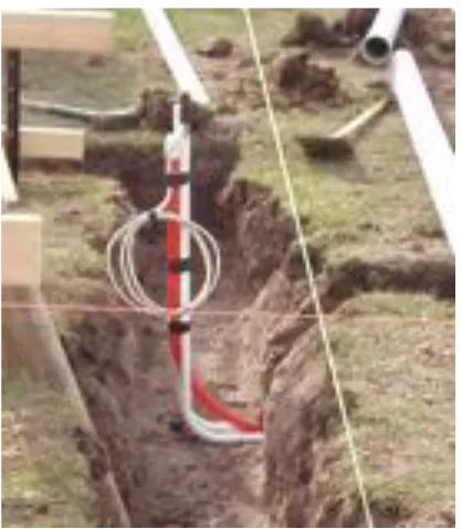
Excavation and laying of conduits for electrical and data services, with draw-wires installed between test cells and existing university building.
Excavation and commencement of pipe installation for PVC stormwater pipes, which was linked to existing university stormwater services.
Figure A3.21 - Installation of conduits with draw-wires for electrical and data services from existing
university building (June 13, 2006)
Figure A3.22 - Installation of conduits with draw-wires for electrical and data services to the enclosed-perimeter platform-floored test cell
[image:19.595.81.286.117.358.2](June 13, 2006)
Figure A3.23 - Installation of storm-water services
[image:19.595.74.530.470.687.2]Figure A3.25 - Unenclosed-perimeter platform-floored test cell (June 13, 2006)
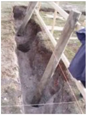
[image:20.595.96.267.422.649.2]Figure A3.26 - Enclosed-perimeter platform-floored test cell (June 13, 2006)
Figure A3.27 - Detail of trench and poles of enclosed-perimeter platform-floored test cell
(June 13, 2006)
Figure A3.28 - Concrete slab-on-ground floored test cell, with pre-fabricated roof trusses in the
June 14, 2006
Weather: fine
Trades on site: carpenters, concreters
Unenclosed-perimeter platform-floored test cell - Concreting of footings for pole supports
Enclosed-perimeter platform-floored test cell
- Installation of steel mesh in strip footings, concreting of strip footings for pole supports
Concrete slab-on-ground floored test cell - Nil activity
Figure A3.29 - Concreting of footings for the unenclosed-perimeter platform-floored test cell
(June 14 2006)
Figure A3.30 - Concreted footing with pole support for the unenclosed-perimeter platform-floored test
Figure A3.31 - Trench mesh installed for the footings of the enclosed-perimeter platform-floored
test cell (June 14 2006)
Figure A3.32 - Strip footings concreted with pole supports in place for the enclosed-perimeter
platform-floored test cell (June 14 2006)
June 15, 2006
Weather: fine
Trades on site: carpenters
Unenclosed-perimeter platform-floored test cell - Nil activity
Enclosed-perimeter platform-floored test cell - Nil activity
Concrete slab-on-ground floored test cell
Figure A3.33 - Concrete slab area levelled with bedding dust (June 15, 2006)
Figure A3.34 - Fabrication and installation of concrete slab formwork for concrete
slab-on-ground test cell (June 15, 2006)
June 16, 2006
Weather: fine
Trades on site: carpenters
Unenclosed-perimeter Platform-floored Test Cell
- Removal of formwork, trimming of pole footings, installation of timber bearers
Enclosed-perimeter Platform-floored Test Cell
- Removal of formwork, trimming of pole footings, installation of timber bearers
Concrete slab-on-ground floored test cell
Figure A3.35 - Unenclosed-perimeter platform-floored test cell: Formwork and supports for concreting of footings have been removed (June 16, 2006)
Figure A3.36 - Enclosed-perimeter platform-floored test cell: Formwork and supports for concreting of
footings have been removed (June 16, 2006)
Figure A3.37 - Enclosed-perimeter platform-floored test cell: Poles have been trimmed and timber
Figure A3.38 - Concrete slab-on-ground floored test cell: Formwork completed and steel reinforcing
mesh installed. PVC pipes for under slab temperature probes are visible (June 16, 2006)
Figure A3.39 - Concreting of the concrete slab-on-ground floored test cell (June 16, 2006)
June 19, 2006
Weather: fine
Trades on site: carpenters
Unenclosed-perimeter platform-floored test cell
- Construction of joists and application of particle board flooring
Enclosed-perimeter platform-floored test cell
- Construction of joists and application of particle board flooring
Figure A3.40 - Enclosed-perimeter platform-floored test cell: Bearers, joists and particle-board platform
floor installed (June 19, 2006)
Figure A3.41 - Concrete slab-on-ground floored test cell: Formwork removed from concrete slab
(June 19, 2006)
June 20, 2006
Weather: fne
Trades on site: carpenters
Unenclosed-perimeter platform-floored test cell
- The 90 x 35mm pine, pre-fabricated wall frames were erected and nail fixed in place.
Enclosed-perimeter platform-floored test cell
- The 90 x 35mm pine, pre-fabricated wall frames were erected and nail fixed in place.
Concrete slab-on-ground floored test cell
Figure A3.42 - The two-man process of erecting the pre-fabricated wall frames: Stage 1 stand up wall
panel (June 20, 2006)
Figure A3.43 - Stage 2: Shuffling wall panel into position and nail fasten to floor (June 20, 2006)
Figure A3.44 - Stage 3: Erect adjoining wall panel (June 20, 2006)
Figure A3.45 - Stage 4: Shuffle second wall panel into position and nail fasten to floor and first panel
(June 20, 2006)
Figure A3.46 - Pre-fabricated wall panels erected for the unenclosed-perimeter
platform-Figure A3.47 - Pre-fabricated wall panels erected for the enclosed-perimeter
platform-Figure A3.48 - Pre-fabricated wall panels erected for the concrete slab-on-ground floored test cell
June 21, 2006
Weather: fine/ overcast Trades on site: carpenters
Similar in nature to June 20, all three test cells had the same type of construction activities, namely:
Unenclosed-perimeter platform-floored test cell - The erection of the pre-fabricated roof trusses. - The application of steel strap wall and roof bracing. - The application of steel fixings for tie-down requirements.
Enclosed-perimeter platform-floored test cell
- The erection of the pre-fabricated roof trusses. - The application of steel strap wall and roof bracing. - The application of steel fixings for tie-down requirements.
Concrete slab-on-ground floored test cell
- The erection of the pre-fabricated roof trusses. - The application of steel strap wall and roof bracing. - The application of steel fixings for tie-down requirements.
Figure A3.49 – Pre-fabricated roof trusses erected and steel strap bracing applied on the unenclosed-perimeter platform-floored test cell (June 21, 2006)
Figure A3.51 - Pre-fabricated roof trusses erected and steel strap bracing applied on the concrete slab-on-ground floored test cell (June 21, 2006)
Figure A3.52 - Roof trusses affixed to wall frames by metal tie-down strap (June 21, 2006)
Figure A3.53 – Wall frame affixed to bottom-plate, particle-board floor and joists by nails, screws
and steel tie-down straps (June 21, 2006) Figure A3.54 – Concrete slab-on-ground floored test cell: Wall frame affixed to bottom-plate by nails and steel tie-down strap. Bottom-plate affixed to concrete slab floor by screws (June 21, 2006)
June 22 to 23, 2006
June 26, 2006
Weather: fine, with increasing cloud
Trades on site: carpenters, fork-lift driver for clay brick delivery
Unenclosed-perimeter platform-floored test cell
- Installation if tie-down requirements for all three test cells completed
Enclosed-perimeter platform-floored test cell
- Installation if tie-down requirements for all three test cells completed.
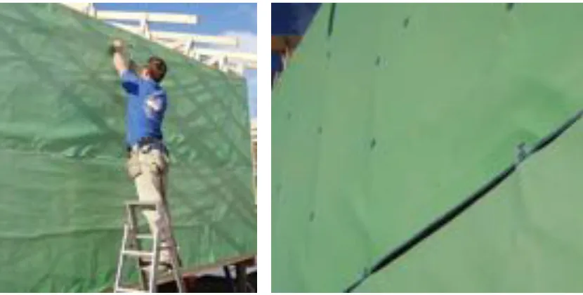
- After introductory training by the researcher, the carpenters commenced the application of the building wrap onto external walls of the unenclosed-perimeter platform-floored test cell. This included the use of steel staples and the taping of all joints.
- After the carpenters had finished applying the building wrap to the unenclosed-perimeter platform-floored test cell, the researcher noted that the current construction method would leave the external corners of the test cells uninsulated. The researcher and Associate Professor Greg Nolan retrofitted insulation into the wall corners by twilight.
Note; This is a commonly missed area of insulation in Australian construction. This was found to be an area of concern for building modelling errors in other research (LomasEppel et al. 1994; LomasMartin et al. 1994).
Concrete slab-on-ground floored test cell
- Installation if tie-down requirements for all three test cells completed.
Clay bricks for the two clay brick veneered test cells delivered to site
the middle test cell. A meeting with the builder determined that a crane would be hired on June 28 to undertake the task of lowering the middle test cell. The researcher was to reassess the site and establish the amount that the middle test cell was to be lowered prior to June 28.
Figure A3.55 - Bricks provided by industry sponsor, delivered to site (June 26, 2006)
[image:31.595.109.524.377.587.2]Figure A3.56 - Reflective foil building wrap and tape provided by industry sponsor (June 26, 2006)
Figure A3.57 - Standard Australian practice with building wrap overlapped and affixed using steel
staples (June 26, 2006)
Figure A3.59 - Standard Australian wall framing with double-studs at external corners (June 26,
2006)
Figure A3.60 – When the building wrap is applied, the double-stud external corners are left
[image:32.595.69.531.372.660.2]un-insulated (June 26, 2006)
Figure A3.61 – After the carpenters had finished, the researcher and Associate Professor Greg Nolan
retrofitted insulation to the external corners by twilight (June 26, 2006)
Figure A3.62 - Associate Professor Greg Nolan applying the last steel staples by twilight (June 26,
June 27, 2006
Nil activity Weather: raining
June 28, 2006
Weather: fine
Trades on site: carpenters, crane operators
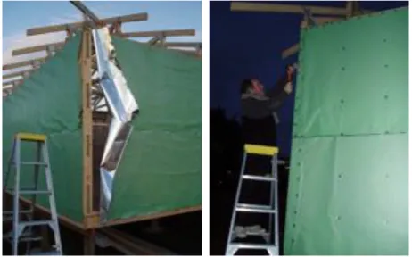
This was an extremely busy day with deliveries of building materials and the height adjustment of the middle (enclosed-perimeter platform-floored) test cell before 10.00am. The remainder of the day was much less active with the resumption of the general construction of the test cells.
Unenclosed-perimeter platform-floored test cell - Nil activity
Enclosed-perimeter platform-floored test cell - Test cell was lowered by 400mm
Concrete slab-on-ground floored test cell
additional time when compared to the current practice. This method ensured that the reflective air-space between the sarking and sheet-metal roofing was established.
The sheet metal roofing, provided by an industry sponsor, arrived on site
Figure A3.63 - Delivery of sheet-metal roofing (June
28, 2006) Figure A3.64 - The poles of the enclosed-perimeter platform-floored test cell are unfastened from the bearers and trimmed in preparation for the
[image:34.595.78.530.441.696.2]lowering of the building (June 28, 2006)
Figure A3.65 - Crane preparation prior to lifting the enclosed-perimeter platform-floored test cell (June
28, 2006)
Figure A3.67 – Carpenter trims pole of the enclosed-perimeter platform-floored test cell (June
28, 2006)
Figure A3.68 - The enclosed-perimeter platform-floored test cell is craned back onto its 400mm
lower poles (June 28, 2006)
Figure A3.69 - Concrete slab-on-ground floored test cell: Reflective foil sarking is rolled out and stapled
to roof trusses (June 28, 2006)
Figure A3.70 - Concrete slab-on-ground floored test cell: Battens are placed over reflective foil sarking
June 29, 2006
Weather: mixed between fine, cloudy and rain Trades on site: carpenters
Unenclosed-perimeter platform-floored test cell
- Reflective foil roof sarking applied and fixed in the same manner as the concrete slab-on-ground floored test cell.
Enclosed-perimeter platform-floored test cell
- Reflective foil roof sarking applied and fixed in the same manner as the concrete slab-on-ground floored test cell.
Concrete slab-on-ground floored test cell - Nil activity
June 30, 2006
Weather: mixed between heavy fog, cloudy and rain Trades on site: carpenters, roofing contractors
After a very cold, foggy and damp start many tasks were completed on day. Like many recent days, work was intermittently stopped by rain. A summary of the primary activities is described below:
Unenclosed-perimeter platform-floored test cell
- Wall wrap applied and fixed in place with steel staples - Wall wrap taped at all joints
- Battens affixed to external frame for fixing plywood cladding - Cement sheet soffit cladding affixed
- Preliminary taping of holes in wall wrap and roof sarking
Enclosed-perimeter platform-floored test cell
- Wall wrap applied and fixed in place with steel staples - Wall wrap taped at all joints
- Damp proof course tape fixed to wall wrap - Cement sheet soffit cladding affixed
- Acknowledgement of holes in wall warp and roof sarking
Concrete slab-on-ground floored test cell - Cement sheet soffit cladding affixed
- Roofing and guttering installation completed
Other Issues
- The fixing of the external battens onto the unenclosed-perimeter platform-floored test cell, (for plywood cladding fixing), raised long term issues for this method of construction. Additional studs were retrospectively installed into the pre-fabricated timber wall framing to better support the plywood cladding and battens. This would reduce the wall area that could receive wall batt bulk insulation.
- Prior to commencing the application and fixing of the wall wrap and roof sarking, the builders attended a trade training event pertaining to this specific task When the wrap was installed, the carpenters were very proud of their ‘best ever’ installation. When the researcher then discussed the issues of the many holes and gaps in the wrap and sarking the builders were concerned that their training did not discuss these issues appropriately. The researcher then explained the triple purpose of insulation, infiltration control and vapour barrier that these materials were designed to perform. As construction progressed, the researcher and John Lilywhite (School of Architecture technical assistant) and the carpenters worked closely together taping holes in the wall wrap as construction progressed.
Figure A3.72 - Unenclosed-perimeter platform-floored test cell: Wall wrap taped at joints and battens affixed ready for application of plywood
cladding (June 30, 2006)
Figure A3.73 – Enclosed-perimeter platform-floored test cell: Wall wrap taped at joints and damp proof
Figure A3.74 – Concrete slab-on-ground floored test cell: Damp proof course affixed to wall frame (June
30, 2006)
Figure A3.75 - Diagram of damp proof course for the concrete slab-on-ground floored test cell
Figure A3.76 – Sheet-metal roofing prepared prior to fixing on concrete slab-on-ground floored test
cell (June 30, 2006)
Figure A3.78 - The building wrap had many holes which required repair (June 30, 2006)
[image:40.595.113.485.350.561.2]Figure A3.79 – The roof sarking had many holes which required repair (June 30, 2006)
Figure A3.80 - Site photograph at the completion of works on June 30, 2006. Unenclosed-perimeter platform-floored test cell at front followed by enclosed-perimeter platform-floored and concrete
July 3, 2006
Weather: heavy fog, early drizzle, then a fine afternoon and evening Trades on site: carpenters, roofing contractors
The weekend of July 1 and 2 was quite stormy with very strong winds. Returning to the test cell construction site on Monday July 3 was a reminder of how susceptible to the elements building construction can be. After the initial shock, the day presented the finest weather for some time and quite a lot of reconstruction and new construction works occurred. The roofing contractor was due back on site after 9.00am, which resulted in co-operative work between the researcher, carpenters (who were on site prior to 7.00am) and the roofing team to remove the damaged wall wrap and roof sarking, apply new roof sarking and re-affix battens and apply sheet-metal roofing. This included many early morning phone calls to the building wrap and sarking sponsors to locate and obtain replacement materials. As this was quite a process-driven day, the taping of the roof sarking had to be left until after the sheet-metal roofing was installed. This required the taping of all roof sarking joints from the inside of the roof space. This was a cramped and difficult task and my thanks go to the school technical assistant who spent the following days in the cramped roof space completing the taping of the roof sarking.
Unenclosed-perimeter platform-floored test cell
- Due to the regular plywood fixing battens on the outside of the test cell, the wall wrap had survived with regular small holes as a result of wind blown debris. The base of the wrap, (which was draped to support the future installation of sub-floor wrap) was in tatters and required removal and reinstallation.
- The roof sarking was in a tattered or non-existent state - Removal of roof battens
- Removal of remnant roof sarking - Application of new roof sarking - Re-fixing of roof battens
Figure A3.81 – Unenclosed-perimeter platform-floored test cell: Early morning reveals damage to
wall wrap and roof sarking (July 3, 2006)
Figure A3.82 – Unenclosed-perimeter platform-floored test cell: Storm damage to subfloor skirt of
wall wrap (July 3, 2006)
Figure A3.83 – Unenclosed-perimeter platform-floored test cell: Storm damage to roof sarking (July
3, 2006)
Figure A3.84 – Unenclosed-perimeter platform-floored test cell: Sheet-metal roof applied and tape
Figure A3.85 – Unenclosed-perimeter platform-floored test cell: Application of plywood cladding
(July 3, 2006)
Figure A3.86 – Unenclosed-perimeter platform-floored test cell: Completion of works July 3, 2006
Enclosed-perimeter platform-floored test cell
Unlike the unenclosed-perimeter platform floored test cell, the wall wrap for this test cell was only held in place by the steel staples. As a result of the storm, much of the wall wrap and roof sarking had been removed. The day entailed:
- Removal of roof battens
- Removal or remnant roof sarking - Application of new roof sarking - Re-fixing of roof battens
- Application of sheet-metal roofing and gutters - Removal of damaged portions of wall wrap - Application of new wall wrap
Figure A3.87 – Enclosed-perimeter platform-floored test cell: Early morning reveals storm damage to
wall wrap and roof sarking (July 3, 2006)
Figure A3.88 – Enclosed-perimeter platform-floored test cell: Completion of works on July 3, 2006
Concrete slab-on-ground floored test cell
Fortunately no wall wrap had been applied to this test cell prior to the weekend storms. The roof, even though only partly finished, had protected the roof sarking. The day’s tasks for this test cell included:
- completion of the sheet-metal roofing and gutters installation
July 4, 2006
Weather: mixed light cloud and clear skies
Trades on site: carpenters, bricklaying contractors
The day included bricklaying, continued taping of wall wrap and roof sarking and installation of furring channels for ceiling plasterboard. After an initial discussion with the bricklayers regarding the importance of maintaining the integrity of the building wall wrap, the brick-laying contractors were provided with some roles of the reflective foil tape and repaired any damaged building wrap as they laid bricks.
Unenclosed-perimeter Platform-floored Test Cell - Completion of plywood wall cladding
- Installation of furring channels for plasterboard ceiling - Taping of roof sarking from the inside
Figure A3.90 – Unenclosed-perimeter platform-floored test cell: Furring channel installed and
taping of roof sarking (July 4, 2006)
Figure A3.91 – Unenclosed-perimeter platform-floored test cell: Plywood cladding completed (July
4, 2006)
Enclosed-perimeter platform-floored test cell
Figure A3.92 -: Enclosed-perimeter platform-floored test cell: Clay brick veneer wall construction commenced (July 4, 2006)
Figure A3.93 – Enclosed-perimeter platform-floored test cell: Base course of clay brick veneer wall (July
4, 2006)
Concrete slab-on-ground floored test cell
- installation of furring channels for the plasterboard ceiling
[image:46.595.187.411.482.655.2]A factor which became more apparent during construction was the ongoing damage inflicted on the building wall wrap and roof sarking. In a normal building project, this damage would be left unrepaired, which must affect infiltration and moisture control during the life of the building (Anis, Quirouette & Rousseau 2007; Mumovic et al. 2005; Swinton, Brown & Chown 1990).
Figure A3.95 - Ongoing reflective tape repairs to
building wall wrap (July 4, 2006) Figure A3.96 - Holes requiring repair in roof sarking (July 4, 2006)
July 5, 2006
Weather: a foggy start, followed by a brief period of sunshine then cloud and rain. Trades on site: carpenters, brick-laying contractors, insulation contractors
[image:47.595.73.528.227.402.2]breadth greater than 100mm. The researcher asked for the gaps to be filled with appropriate insulation. For a second time the researcher was called in to inspect the wall batt insulation. This time there was a better coverage but gaps of 50mm or more were visible on all walls. The researcher requested that all gaps be filled before approval would be given. On the third call for inspection no obvious gaps were visible and the contractors were allowed to proceed. When the contractors commenced installing the ceiling insulation, a lesson had been learned and no gaps were visible. The plasterboard for wall and ceiling lining, which was provided by an industry sponsor, was delivered to the test cell site. This posed a few logistical issues due to persistent rain and limited dry zones within the test cells. Eventually, after some hasty cleaning, the plasterboard was placed diagonally on the floor of each test cell.
Unenclosed-perimeter platform-floored test cell
- Installation of rock-wool wall batt insulation as discussed above
[image:48.595.98.265.411.585.2]- The partial installation of ceiling Glass-wool batt insulation as discussed above
Figure A3.97 -: Unenclosed-perimeter platform-floored test cell: Rock-wool wall batt insulation
installed (July 5, 2006)
Figure A3.98 – Unenclosed-perimeter platform-floored test cell: Glass-wool ceiling batt insulation
partially installed (July 5, 2006)
Enclosed-perimeter platform-floored test cell
[image:48.595.301.524.412.584.2]Concrete slab-on-ground floored test cell
[image:49.595.304.532.164.331.2] [image:49.595.73.528.449.620.2]- Application of wall wrap, fixed in place by steel staples and taped at all joints
Figure A3.101 - Concrete slab-on-ground floored test cell: Application of building wall wrap (July 5,
2006)
Figure A3.102 - Concrete slab-on-ground floored test cell: Wall wrap application by carpenters prior
to joint taping by researcher (July 5, 2006) Figure A3.99 – Enclosed-perimeter platform-floored
test cell: Installation of subfloor wall vent (July 5, 2006)
Figure A3.100 – Enclosed-perimeter platform-floored test cell: Integration of damp proof course
July 6, 2006
Weather: a foggy start followed by a fine morning and afternoon
Trades on site: carpenters, brick-laying contractors, insulation contractors, plaster contractors
Similar to July 5, this day required the researcher to extensively co-ordinate and assist in the co-operation of several trades and their activities.
Unenclosed-perimeter Platform-floored Test Cell - Plasterboard wall sheeting affixed to walls
- Plasterboard ceiling sheeting affixed to furring channels - Door jamb and trims installed
- Door hung but no latches installed
- Roof space access-hatch constructed but not enclosed
Figure A3.104 – Unenclosed-perimeter platform-floored test cell: Application of ceiling plasterboard
(July 6, 2006)
Figure A3.105 - Unenclosed-perimeter platform-floored test cell: Application of wall plasterboard
(July 6, 2006)
Figure A3.106 - Unenclosed-perimeter platform-floored test cell: Installation of door jamb and
external trims (July 6, 2006)
Figure A3.107 -: - Unenclosed-perimeter platform-floored test cell: Flexible external sealant applied to external trims to reduce risk of infiltration
(July 6, 2006)
Enclosed-perimeter platform-floored test cell - Plasterboard wall sheeting affixed to walls
- Door hung but no latches installed
Figure A3.108 – Enclosed-perimeter platform-floored test cell: Ongoing bricklaying with gaps being left for knock-out wall panels (July 6, 2006)
Figure A3.109 - Enclosed-perimeter platform-floored test cell: Wall and ceiling insulation installed, plasterboard applied to walls and ceiling
(July 6, 2006)
Concrete slab-on-ground floored test cell - Installation of wall batt insulation
- Partial installation of ceiling batt insulation - Door jamb and trims installed
- Door hung but no latches installed
Figure A3.110 - Concrete slab-on-ground floored test cell: Rock-wool wall batt insulation installed
(July 6, 2006)
Figure A3.111 - Concrete slab-on-ground floored test cell: Glass-wool ceiling batt insulation partially
Other Notes
It was established in the morning that there was not enough insulation on site and the researcher organised additional supply with the material sponsor, which arrived in the following days. This was after the insulation contractors had left the site and the carpenters and researcher completed the insulation installation.
[image:53.595.331.499.360.585.2] [image:53.595.98.268.362.587.2]An aspect of extra care at this stage was the application of measures to reduce infiltration losses. As the door jambs and doors were being installed, foam rubber in an adhesive tape form was applied to the internal edges of the door jamb. Rubber trims were also affixed to the base of each door to limit infiltration under the door. The effectiveness of these measures would be tested in the environmental measurement stage of the research.
Figure A3.112 - Detail of foam-rubber door seal being applied to door jamb. Note: Gap that exists
above door jamb (July 6, 2006)
Figure A3.114 - Rubber draft seal affixed to base of door (July 6, 2006)
July 7, 2006
Weather: a foggy start followed by a fine morning and afternoon
Trades on site: carpenters, brick-laying contractors, plaster contractors, school technical assistant (painting)
Unenclosed-perimeter platform-floored test cell
- Application of skim coat to plaster joints and to cover screw fixings - Spray painting of the plywood clad external walls
-Figure A3.115 - Unenclosed-perimeter platform-floored test cell: The plasterboard sheet has received a plaster skim coat to cover joints and
screw fixings (July 7, 2006)
Enclosed-perimeter platform-floored test cell
- Completion of brick-laying the external veneer wall
- Application of skim coat to plaster joints and to cover screw fixings
Concrete slab-on-ground floored test cell
- Plasterboard wall sheeting affixed to walls
- Plasterboard ceiling sheeting affixed to furring channels
Figure A3.117 – Enclosed-perimeter platform-floored test cell: Brick-laying completed with expansion joints in the wall for the knock-out
panels (July 7, 2006)
Figure A3.118 - Enclosed-perimeter platform-floored test cell: The plasterboard sheet has received a plaster skim coat to cover joints and
screw fixings (July 7, 2006)
July 8, 2006
Weather: a fine morning and afternoon Trades on site: brick-laying contractors
Enclosed-perimeter platform-floored test cell
- Insertion of backing-rod into the expansion joints for the knock-out panels
Figure A3.119 - Unenclosed-perimeter platform-floored test cell: Completion of works July 8, 2006
Figure A3.120 - Enclosed-perimeter platform-floored test cell: Brick-laying completed July 8,
2006
Concrete slab-on-ground floored test cell
- Repairs to damaged wall wrap with reflective tape - Joints in wall wrap re-taped
- Fixing in place and taping of damp proof course
- Commencement of brick-laying the external clay brick veneer wall.
Figure A3.121 - Concrete slab-on-ground floored test cell: All holes in building wrap repaired prior to
commencement of brick-laying (July 8, 2006)
Figure A3.122 - Concrete slab-on-ground floored test cell: Detail photograph of damp proof course
July 10, 2006
Weather: mixed cloud cover
Trades on site: brick-laying contractors, plaster contractors, electrical contractors
Unenclosed-perimeter platform-floored test cell - Sanding and finishing of plaster skim coats - Wall / ceiling cornices glued in place
-Figure A3.123 - Concrete slab-on-ground floored test cell: Detail photograph of damp proof course
[image:57.595.329.499.89.261.2] [image:57.595.75.532.492.695.2]corner (July 8, 2006)
Figure A3.124 - Concrete slab-on-ground floored test cell: First course of clay bricks laid (July 8,
2006)
Figure A3.125 - Unenclosed-perimeter platform-floored test cell: Application of plaster glue to
cornice (July 10, 2006)
Figure A3.126 - Unenclosed-perimeter platform-floored test cell: Fixing cornice in place (July 10,
Enclosed-perimeter platform-floored test cell - Sanding and finishing of plaster skim coats - Wall / ceiling cornices glued in place
Concrete slab-on-ground floored test cell
- Application of first skim coat to plaster joints and to cover screw fixings - Sanding and finishing of plaster skim coats
- Wall / ceiling cornices glued in place - Ongoing brick-laying
Other
[image:58.595.72.296.442.609.2]Electrical contractor came on site to meet with researcher and finalise methods of installing internal electrical services with minimal effect on the envelope of the three test cells
Figure A3.127 - : Concrete slab-on-ground floored test cell: Application of plaster skim coat to
plaster-board joint (July 10, 2006)
Figure A3.128 - Concrete slab-on-ground floored test cell: Brick-laying well underway with knock-out
July 11, 2006
Weather: mixed cloud cover
Trades on site: brick-laying contractors
The primary construction of the test cells was completed on this day with carpenters attending the site over the following days to remove excess materials and to generally clean up the site debris, including: material off-cuts, waste and other assorted construction items. Once the site was clean, the safety fence which had surrounded the site was removed.
Unenclosed-perimeter Platform-floored Test Cell - Nil
Enclosed-perimeter Platform-floored Test Cell - nil
Concrete Slab-on-ground Floored Test Cell - Completion of brick-laying
July 12 to August 23, 2006
[image:60.595.88.512.232.368.2] [image:60.595.185.412.466.636.2]This time was spent on: internal and external painting, installing infiltration reduction measures, the completion and testing of electrical services, installation of test cell heating and test cell and site cleaning. To save costs, the internal and external painting of the test cells was completed by the school technical assistant and the researcher.
Figure A3.130 - The thermal performance tests cells after site cleaning and removal of safety fence (July 15, 2006)
Bibliography
Agami Reddy, T, Maor, I & Panjapornpon, C 2007, 'Calibrating detailed building energy
simulation programs with measured data - part 1: general methodology (RP-1051)',
HVAC&R Research, vol. 13, no. 2, pp. 221-241.
Anis, W, Quirouette, R & Rousseau, J 2007, Air barriers & vapor barriers.
Lomas, K 1994, Empirical validation of thermal building simulation programs using test
room data: volume 3 - working reports, IEA Energy Conservation in Buildings and
Community System Program Appendix 21 and IEA Solar Heating and Cooling Programme Task 12, U.K.
Lomas, K, Eppel, H, Martin, C & Bloomfield, D 1994, Empirical validation of thermal
building simulation programs using test room data: volume 1 - final report, IEA Energy
Conservation in Buildings and Community System Program Appendix 21 and IEA Solar Heating and Cooling Programme Task 12.
Lomas, K, Martin, C, Eppel, H, Watson, M & Bloomfield, D 1994, Empirical validation of thermal building programs using test room data: volume 2 - empirical validation
package, IEA Energy Conservation in Buildings and Community System Program
Appendix 21 and IEA Solar Heating and Cooling Programme Task 12.
Mumovic, D, Ridley, I, Oreszczyn, T & Davies, M 2005, 'Condensation risk: comparison of steady-state and transient methods', viewed 2007.
Swinton, M, Brown, W & Chown, G 1990, 'Controlling the transfer of heat, air and moisture
through the building envelope', paper presented to Building Science Insight '90, Small