Abstract: The paper presents a fast initial speed estimation method resolved by using a Fuzzy logic controller. This is applied for sensorless induction motor drives under low speed operation based on the second order differential of the secondary flux. At restarting time of an induction motor, it produces unwanted disturbance torque. This disturbance can be reduced by fast estimation based on FLC. The performance of proposed method is tested by using MATLAB/Simulink and estimation time has been compared with conventional controller like PI. Simulation results shows that FLC is more efficient than PI control.
Keywords: Adaptive Flux Observer (AFO), Direct Current Injection (DCI), Fuzzy Logic Controller (FLC), Second Order Differential of the Secondary Flux (SOD-SF), Sensorless induction motors, Speed Estimator (SE).
I. INTRODUCTION
Induction machine drives without speed sensors have been embraced in industry applications inferable from their favorable circumstances. For example, simple preservation, high dependability, minimal effort and reduced size. By use of high frequency signal injected method and adaptive estimation technique, the performance and robustness are improved. Some of the applications are conveying devices, production devices and traction system. The induction motor with high inertia load rotates long time, when inverter is in off state. Due to inertia, the rotor run continuously then inverter should be restart, is common in certain application of traction system. Under restart method the interruption of power supply occurs due to insufficient power source. As to overcome this problem in restart operation the secondary flux be estimated with Voltage Controlled Current Regulated PWM (VCCR-PWM) inverter, was developed an option by Rowan and Kerkman to useful inverters, during conditions of ordinary working and over-burden. VCCR-PWM inverter is related to recurrence controller be solution for misstep activity on present and later of over-burden condition and on reconnection to a turning
Revised Manuscript Received on September 06, 2019
Anka Rao Mogili, EEE department, JNTUA University,
Ananthapuramu, India. Email: [email protected]
Sai Sateesh Kadiri, EEE department, JNTUA University,
Ananthapuramu, India. Email: [email protected]
M. Vijaya Kumar, EEE department, JNTUA University,
Ananthapuramu, India.
engine under burden with interruption of power [3], proposes an estimation technique for rotational bearing and speed as per the normal for the air conditioner machine. This strategy [4] is conceivable to assume responsibility for the perfect machine by an inverter with an info and yield linearization technique is proposes to connect for restarting methods [5]. In it, the rotor with transition conditions of voltage are linearized with inverter recurrence info and the stator actuated voltage by rotor motion, with the stator flow supposition is consistent. Because of linear method, a straight forward d-pivot rotor motion actuated condition of voltage is acquired and remunerated with compensator correspondingly. In these techniques, the essential recurrence be controlled with the point as d-pivot instigated potential be zero. There is a base speed restriction nearly 175 rpm to the restarting activity [6], in fact that the speed estimator dependent on back emf weakens at low speed. The technique [7], difference between rotor frequency and evaluated frequency happens estimation of unsettling influence torque be not same as its real worth. This error makes the slip recurrence increment, which diminishes torque of engine and motion of rotor. To adapt to the issue, current error of torque is remunerated with controller of PI, repays an unsettling influence torque in motor test system. Likewise, considering the impact brought about inverter with PWM and an improved starting speed estimator was proposed to take out small oscillations. In this paper ripple free, speed stability and unwanted disturbance torque of drive results in simulation waveforms with AFO and SOD-SF.
II. SPEEDESTIMATIONPRINCIPLEDURINGDCI (DIRECTCURRENTINJECTION)
In it, the guideline of present estimation of speed technique with the SOD-SF be displayed. Firstly, the period of time to the Secondary Flux (SF) is determined as direct current flows in forced to acceptance motor. Later, issues of unwanted disturbance torque and estimation of basic speed in low range are determined.
Improvement of Fast Initial Speed Estimation
Using Fuzzy Logic Control Technique for
Induction Motors in the Low Speed Range
A. SECONDARY FLUX (SF) EQUATION
Firstly, with restart process by use of DCI is clarified. The reference voltages are obtained by current controller. In the estimation of basic speed, the necessary frequency 𝜔1 be zero and current reference of d axis 𝑖𝑑∗ be
steady value and current reference of q axis 𝑖𝑞∗ be zero.
Later, fulfillment with estimation of basic speed, an ordinary speed estimation allows to start. The estimation of proposed method takes DCI to inverter at initial step of restart operation. The SF obtained with relation of time. Let SF vector ∅𝑑𝑞𝑟 = [∅𝑑𝑟 ∅𝑞𝑟]𝑇, the stator current vector
𝑖𝑑𝑞𝑠 = [𝑖𝑑𝑖𝑞]𝑇, mutual inductance M, resistance of
secondary 𝑅𝑟, inductance of secondary 𝐿𝑟, speed of rotor in
electrically 𝜔𝑟𝑒, and identity matrix I. The state condition of
the SF is mentioned is,
𝑑
𝑑𝑡∅𝑑𝑞𝑟 = A∅𝑑𝑞𝑟 + M 𝑅𝑟
𝐿𝑟𝑖𝑑𝑞𝑠
(1)
where, 𝐴 = −𝑅𝑟
𝐿𝑟𝐼 − 𝜔1− 𝜔𝑟𝑒 𝐽 , J =
0 −1
1 0 .
assume ∅𝑑𝑞𝑟 0 as ∅𝑑𝑞𝑟 at t = 0, calculation of (1) is,
∅𝑑𝑞𝑟 = 𝑒𝐴𝑡∅𝑑𝑞𝑟 0+ 𝑒𝐴𝑡
𝑡
0
𝑀𝑅𝑟
𝐿𝑟
𝑖𝑑𝑑𝑡
= 𝑒𝐴𝑡∅
𝑑𝑞𝑟 0+ 𝐴−1 𝑒𝐴𝑡− 𝐼 𝑀 𝑅𝑟
𝐿𝑟𝑖𝑑 (2)
The flux with residual ∅𝑑𝑞𝑟 0 be very low value,
computation the product of matrix in second term of (2) and ∅𝑑𝑞𝑟 in obtained matrix format is,
∅𝑑𝑟
∅𝑞𝑟 =
1 𝑅𝑟
𝐿𝑟 2
+ 𝜔𝑟𝑒2
×
𝑒− 𝑅 𝑟𝐿𝑟 𝑡 𝑅𝑟
𝐿𝑟cos 𝜔𝑟𝑒𝑡 + 𝜔𝑟𝑒sin 𝜔𝑟𝑒𝑡 +
𝑅𝑟
𝐿𝑟
𝑒− 𝑅 𝑟𝐿𝑟 𝑡 −𝜔𝑟𝑒cos 𝜔𝑟𝑒𝑡 −𝑅𝑟
𝐿𝑟sin 𝜔𝑟𝑒𝑡 + 𝜔𝑟𝑒
𝑀𝑅𝑟
𝐿𝑟𝑖𝑑
(3)
In the method of conventional, includes [3] SF with ripple frequency period. In any case SF is obtained indirectly. The currents of motor or reference voltages are detected instead of SF The high ripple period of low speed rotor is observed with non positive torque at restart operation. The SF are denoted as ∅𝑑𝑟 , ∅𝑞𝑟.The non positive torque is obtain with
multiplication of flux of q axis ∅𝑞𝑟 and current of d axis. At
some point speed of rotor in electrically 𝜔𝑟𝑒 is sufficiently
large at 𝑅𝑟
𝐿𝑟, from (3) flux of q axis ∅𝑞𝑟 reduces as speed of rotor raises. Thus, method of conventional in low speed observes the ripple duration with an unwanted disturbance
B. PROPOSED METHOD
If the method of conventional is completed in low duration, then unwanted disturbance torque is stifled. As to decrease the time of estimation, SOD-SF is shown in this paper. Calculated SOD-SF from (3) is,
𝑑2 𝑑𝑡2
∅𝑑𝑟
∅𝑞𝑟 =
𝑒− 𝑅 𝑟𝐿𝑟 𝑡 −𝑅𝑟
𝐿𝑟cos 𝜔𝑟𝑒𝑡 − 𝜔𝑟𝑒sin 𝜔𝑟𝑒𝑡
𝜔𝑟𝑒cos 𝜔𝑟𝑒𝑡 −
𝑅𝑟
𝐿𝑟sin 𝜔𝑟𝑒𝑡 𝑀𝑅𝑟
𝐿𝑟
(4)
Let at t = 0, ∅𝑞𝑟 0 as ∅𝑞𝑟 and 𝑑2
𝑑𝑡2∅𝑞𝑟 0 are assumed to the
second row of (4) is,
𝑑2
𝑑𝑡2∅𝑞𝑟 0= 𝑀
𝑅𝑟
𝐿𝑟𝜔𝑟𝑒𝑖𝑑 .
(5)
speed of rotor at starting solved as,
𝜔𝑟𝑒 =
𝐿𝑟 𝑀𝑅𝑟𝑖𝑑
𝑑2
𝑑𝑡2∅𝑞𝑟 0
(6)
This shows the differentiation of second order ∅𝑞𝑟 at t=0
gives rotor speed initially 𝜔𝑟𝑒. The estimation resulted in
small time period. Hence, an unwanted torque be decreased at estimation of speed initially. In other case, the value of 𝑅𝑟
is to be needed in present method. The speed of estimation controls the value of 𝑅𝑟 in (6). Therefore, 𝑅𝑟 measurable in
motor by use of thermometer or estimators of resistance.
III. SYSTEMDESIGN
In this part the fundamental design of controller having speed without sensor is reported firstly. Later, the layout as inverter controller with PWM technique shown in proposed method of estimating speed. At last, simulation results be exhibited for suggested method.
A. FUNDAMENTAL SYSTEM DESIGN
The Fig.1 demonstrates speed sensor-less drive framework of paper. Estimated reference voltages 𝑣𝑑∗ and 𝑣𝑞∗ are
Fig.1. Fundamental system design diagram Currents of phase are identified with sensors of current and changes as 3∅ to 2∅ with balanced terms. The usual speed of rotation is approximated with AFO, to obtain superior characteristics in the range of low speed. The SF is fixed, estimator of speed uses to estimate the current of d axis. The terms define as gain of proportional 𝐾𝜔𝑃, gain of
integral 𝐾𝜔𝐼 and evaluated current of d axis 𝑖 𝑑. The
condition of speed estimation is,
𝜔𝑟𝑒 = 𝐾𝜔𝐼 𝑖𝑑− 𝑖 𝑑 𝑑𝑡 + 𝐾𝜔𝑃 𝑖𝑑− 𝑖 𝑑 (7)
The main frequency 𝜔1 is total of angular slip frequency
referred as 𝜔𝑠𝑒∗ and the evaluated speed rotation as 𝜔𝑟𝑒.
During steady operation condition, the angular slip frequency is taken from reference of current 𝑖𝑞∗ and
evaluated flux of d axis 𝜙 𝑑𝑟 is appeared in (8).
𝜔𝑠𝑒∗ = 𝑀𝑅𝑟𝑖𝑞∗
𝐿𝑟𝜙𝑑𝑟
(8)
In further case, angular slip frequency and reference current of q axis are places with zero value.
B. ESTIMATOR OF IDEAL INITIAL SPEED
Fig.2. Estimator of ideal initial speed
This discuss about to acquire the axis of q with SOD-SF as reference voltage 𝑣𝑞∗. The primary frequency 𝜔1 be zero in
estimation of speed at initially. The terms define as resistance of primary 𝑅𝑠, inductance of primary 𝐿𝑠and
coefficient of leakage 𝜎, respectively, then voltage of q axis derived as,
𝑣𝑞 = 𝑅𝑠𝑖𝑞+ 𝑑
𝑑𝑡𝜎𝐿𝑠𝑖𝑞+ 𝑑 𝑑𝑡
𝑀
𝐿𝑟∅𝑞𝑟 (9)
Consider 𝑖𝑞∗= 0 (reference of q axis) in estimation mode of
speed at initially. So after substituting 𝑖𝑞 = 0 in (9), after
differentiating (9). Thus, SOD with the flux of q axis is,
𝑑2
𝑑𝑡2∅𝑞𝑟 =
𝐿𝑟 𝑀 𝑑
𝑑𝑡𝑣𝑞
(10)
SOD-SF is shown in (10) with the differential computation of 𝑣𝑞. By substituting (10) in (6) to get rotor speed at
initially. The Fig.2. is formed with (6), which shows the estimator of ideal initial speed. In Fig.2, voltage of q axis 𝑣𝑞is restored by reference voltage as 𝑣𝑞∗. The inverter with
reference voltages 𝑣𝑑∗ and 𝑣𝑞∗, currents of motor 𝑖𝑑 and 𝑖𝑞,
and calculated speed 𝜔𝑟𝑒0 ∗ in the estimation of speed at
initial operation. The reference current of d axis 𝑖𝑑∗is
consider at zero time of step function . At the same time, the d-axis voltage 𝑣𝑑 ∗ quickly varies and 𝑖𝑑 combines to 𝑖𝑑∗ and
reference voltage of q axis 𝑣𝑞∗ be low value. By the (5)
SOD-SF related linearly with current of d axis 𝑖𝑑. As to
acquire the 𝑣𝑞∗ value in the computation of speed, reference
current of d axis 𝑖𝑑∗ value is fixed. In the simulation,
estimation of speed at initially 𝜔𝑟𝑒0 ∗ be zero. The estimation
of speed at initial mode have some disturbance with the differentiation condition affected by voltage of inverter with PWM. Thus, the harmonics are eliminated nearly in 10 milli sec period. The estimation of speed in (6) at t = 0, otherwise the calculated speed diminishes 20 milli sec later.
C. ESTIMATOR OF IMPROVED INITIAL SPEED TO INVERTERS WITH PWM
Fig.3. Estimator of improved initial speed The Fig.3 demonstrates the estimator of improved initial speed. The estimator of ideal speed is in Fig.2. assumed value be neglected at t = 0. At (3) the term of exponential
exp[-(𝑅𝑟
𝐿𝑟)t] involved in flux of q axis, magnitude in SF diminishes with constant time of secondary. In this manner, flux of SOD diminishes likewise. As to neglect the term of
exponential, the inverse of this exp[-(𝑅𝑟
𝐿𝑟)t] as appeared in
The reference voltage 𝑣𝑞∗ resulted in estimation of speed
with particular time period, test begin with 𝑡1 and end with
𝑡2. The high value of 𝑡2 takes place when the frequency of
PWM be small. At t = 0, rotor initial speed calculation is complicated. Constant time 𝑡2 - 𝑡1 is mandatory in
estimation of speed. Differentiation output
with
waveform of sine having ripple terms are given to the average of moving. The time period 𝑇𝑠 be constantly used incalculation of differentiation with 𝑡1 and 𝑡2, an average of
moving is,
𝜔𝑎𝑣𝑒 =
𝑇𝑠
𝑡2− 𝑡1
×
sin (𝜔𝑟𝑒 𝑘+1 𝑇𝑠+𝑡1)−sin (𝜔𝑟𝑒 𝑘𝑇𝑠+𝑡1 )
𝑇𝑠 (𝑡2−𝑡1)/𝑇𝑠
𝑘=0
(11)
Assumed settling point of rotor at 𝜃1= 𝜔𝑟𝑒 𝑡1 and
𝜃2= 𝜔𝑟𝑒 𝑡2 in t = 𝑡1 and t = 𝑡2. When sampled period 𝑇𝑠 is
small, then (11) changes in integration form is,
𝜔𝑎𝑣𝑒 = 𝜃2−𝜃11 𝜔𝜃𝜃2 𝑟𝑒 𝑐𝑜𝑠
1 𝜃𝑑𝜃
= 𝑠𝑖𝑛𝜃2−sin 𝜃1
𝜃2−𝜃1 𝜔𝑟𝑒
(12)
Where 𝜃1= 𝜔𝑎𝑣𝑒𝑡1 and 𝜃2= 𝜔𝑎𝑣𝑒𝑡2 are substituted in
(12) .
𝜔𝑟𝑒0=
sin 𝜔𝑎𝑣𝑒𝑡2−sin 𝜔𝑎𝑣𝑒 𝑡1
𝜔𝑎𝑣𝑒𝑡2−𝜔𝑎𝑣𝑒𝑡1 𝜔𝑎𝑣𝑒
(13)
Speed of estimation at initially 𝜔𝑟𝑒0 is unintended speed for
the estimator of speed with AFO showed in Fig.1.
D. ESTIMATION OF SPEED WITH AFO
The speed of rotor, estimated by use of AFO is obtained later an initial speed of rotor is observed. The suggested method in estimation of speed decreases unwanted large frequency with calculation of differentiation. The estimated initial speed included an error which is common to obtain the stability withAFO. In this part, about constant error of speed estimation and stable condition be discussed. Initially, induction motor (IM) state conditions
are shown. State variable vector 𝒙𝑑𝑞 = 𝑖𝑑𝑞𝑠𝜙𝑑𝑞𝑟 𝑇
, input
matrix B = 1
𝜎 𝐿𝑠
1 𝜎 𝐿𝑠 0 0
𝑇
,vector voltage 𝑣𝑑𝑞𝑠 =
𝑖𝑑𝑞𝑠𝜙𝑑𝑞𝑟 𝑇
,gain matrix of feedback G, output matrix C and
resistance 𝑅𝑛 = 𝑅𝑠+ 𝑀2
𝐿𝑟2𝑅𝑟, the state condition of IM is (14)
and observer flux is (15).
𝑑
𝑑𝑡𝒙𝑑𝑞 = 𝐴𝒙𝑑𝑞+ 𝐵𝑣𝑠
(14)
𝑑 = 𝐴 𝒙𝑑𝑞 + 𝐺𝐶 𝒙𝑑𝑞− 𝒙𝑑𝑞 + 𝐵𝑣𝑠
where, A= 𝑨𝑨11 𝑨21
12 𝑨22
𝑨11 = 𝑅𝑛/(𝜎𝐿𝑠)𝑰 − 𝜔1𝐽
𝑨21= 𝑀 𝜎 𝐿𝑠𝐿𝑟{
𝑅𝑟
𝐿𝑟𝑰 − 𝜔𝑟𝑒𝐽}
𝑨12= 𝑀 𝑅𝑟
𝐿𝑟𝑰
𝑨22= − 𝑅𝑟
𝐿𝑟𝑰 − 𝜔𝑠𝑒𝐽
C =1 0 0 1
0 0
0 0
(16)
Parameter matrix of motor 𝐴 is identical as A, excluding frequency of slip and speed rotation are stated to 𝐴 with estimated values. The Laplace term „s‟ used to estimate angular slip frequency 𝜔𝑠𝑒, angular halt frequency from
estimation of current observer 𝜔𝑐 and changeable term q .
Gain matrix of feedback observer G is (15) is
𝐺 = 𝑔𝜔11 𝑔21
1 𝑔22
𝑀𝑅𝑟/𝐿𝑟 0
0 𝑀𝑅𝑟/𝐿𝑟
T
where, 𝑔11= 𝑔22= 𝜔𝑐,
𝑔21= −𝜔1−
𝑠+𝑅 𝑠
𝜎 𝐿𝑟+ 𝑀 2𝑅 𝑟 𝜎 𝐿𝑠𝐿𝑟2+𝑔11
𝑠+𝑅 𝑟
𝐿𝑟
×
{𝜔𝑠𝑒− 𝑞𝑠𝑔𝑛 𝜔1 𝜔𝑠𝑒 + 1 }
(17)
Fig.4. AFO Design Diagram
AFO consider by (15) and (17) are shown in Fig.5. The (15) and (17) are in Fig.5. shown by a line. AFO bounded by a dotted line. The error of consider input currents either 𝑖𝑞𝑠 − 𝑖 𝑞𝑠 or 𝑖𝑑𝑠 − 𝑖 𝑑𝑠of estimation speed
The state condition of error with dissimilarity of (14) and (15). Vector of state error 𝑒𝑑𝑞 = [𝑥𝑑𝑞 − 𝑥 𝑑𝑞]. The condition
of state error is,
𝑑
𝑑𝑡𝑒𝑑𝑞 = 𝐴 − 𝐺𝐶 𝑒𝑑𝑞+ (𝐴 − 𝐴 )𝑥 𝑑𝑞 (18)
The estimation of speed error as ∆𝜔𝑟𝑒 = 𝜔𝑟𝑒− 𝜔𝑟𝑒.
Hence, result of (18) is,
𝑒𝑑𝑞 = (𝑠𝐼 − 𝐴 + 𝐺𝐶)−1 × −
𝑀
𝜎 𝐿𝑠𝐿𝑟𝜙 𝑑𝑟 0𝜙 𝑑𝑟
𝑇
∆𝜔𝑟𝑒
(19)
The cofactors are 𝐶21, 𝐶22, 𝐶41, 𝐶42 for [𝑠𝐼 − 𝐴 + 𝐺𝐶] and
an error with frequency of slip ∆𝜔𝑠𝑒 = 𝜔𝑠𝑒− 𝜔𝑠𝑒.This
paper involves, an error with frequency of slip ∆𝜔𝑠𝑒 and
stable AFO are presented shown in Fig.1, with an approximated speed, currents and reference voltages are taken to AFO in the closed loop structure. The constant error used to make the system stable. Hence, suggested method takes an error for an estimation of d axis current till coincides with estimate speed. The current errors of d axis and q axis are in transfer function from estimation speed error are in (20) and (21) as,
𝑖𝑑 − 𝑖 𝑑 =
−𝜎𝐿𝑀
𝑠𝐿𝑟𝐶21+ 𝐶41
(𝑠 + 𝑅𝑛
𝜎𝐿𝑠+ 𝑔22)𝐶22
𝜙 𝑑𝑟∆𝜔𝑟𝑒
=
𝑀 𝜎 𝐿𝑠𝐿𝑟(𝜔𝑟𝑒𝑠+
𝑅 𝑟 𝐿𝑟 𝜔 1)𝜙𝑑𝑟
𝑠+𝑅 𝑟
𝜎 𝐿𝑠+𝑔22 (𝑠2+2 𝑅 𝑟 𝐿𝑟𝑠+
𝑅 𝑟 𝐿𝑟 2
+𝜔𝑠𝑒2)
∆𝜔𝑟𝑒 (20)
𝑖𝑞− 𝑖 𝑞= − 𝑀
𝜎 𝐿𝑠𝐿𝑟𝐶22+ 𝐶42
(𝑠+𝑅 𝑛
𝜎 𝐿𝑠+𝑔22)𝐶22
𝜙 𝑑𝑟∆𝜔𝑟𝑒
=
𝑀 𝜎 𝐿𝑠𝐿𝑟𝜙𝑑𝑟
𝑠+𝑅 𝑟
𝐿𝑟 𝑠+𝜎 𝐿𝑠𝑅 𝑟+𝑔22 (𝑠2+2𝑅 𝑟𝐿𝑟𝑠+ 𝑅 𝑟𝐿𝑟 2
+𝜔𝑠𝑒2) ×
𝑠3+ 2𝑅𝑟
𝐿𝑟
𝑠2+ 𝑅𝑟
𝐿𝑟 2
+ 𝜔𝑠𝑒2
+ 𝜔𝑟𝑒 𝜔𝑠𝑒+ 𝑞𝑠𝑔𝑛 𝜔1 𝑠
+𝑅𝑟
𝐿𝑟
𝜔1∆𝜔𝑠𝑒+ 𝑞 𝜔1 ∆𝜔𝑟𝑒
(21)
IV. ESTIMATOROFIMPROVEDINITIALSPEED WITHFLC
In improved method, controller of current used in fundamental system design diagram of Fig.1. The controller of current is replaced with FLC to obtain better performance. The fundamental system design diagram replaces with FLC in Fig.5.
Fig.5. Estimator of improved initial speed with FLC A. Fuzzy control system
The control work is depends on logic of fuzzy is broadly utilized in machine control. It shows an uncomplicated term with constant attributes between 0 and 1. The enhanced logic works on discrete estimation of 0 or 1. The subject suggest the logic of fuzzy as false or true. For an instance, in logic of fuzzy with neural interface system and genetic algorithm are commonly used. Thus, it is easier with an effective performance.
B. Fuzzy sets
The representation of fuzzy control are to be mapped each other in all sets is called as fuzzy sets. The process of changing real scalar value into fuzzy value is known as fuzzification. The membership functions of inputs and outputs be as follows,
Input 1 Membership Function
Output Membership Function
[image:6.595.318.534.60.187.2]Fig.6. Input and output membership functions of FLC TABLE - 1: FLC rule base for speed
V. SIMULATIONRESULTS
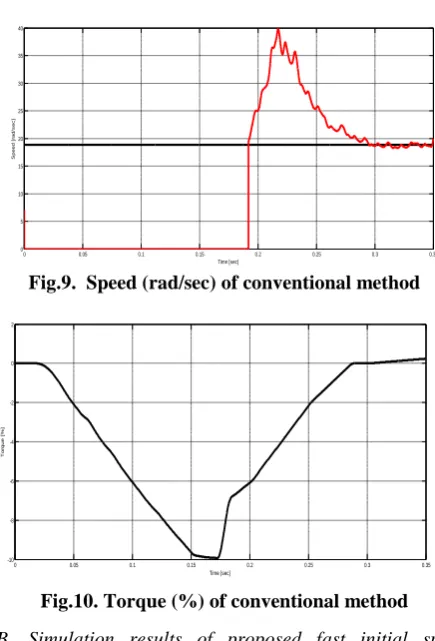
A. Simulation results of conventional control method at restart operation of 90 r.p.m (18.85 rad/sec).
[image:6.595.51.290.205.346.2]Fig.7. Stator currents of conventional method
[image:6.595.314.532.215.536.2]Fig.8. Voltages 𝒗𝒅∗ and 𝒗𝒒∗ of conventional method
Fig.9. Speed (rad/sec) of conventional method
Fig.10. Torque (%) of conventional method B. Simulation results of proposed fast initial speed estimator control method at restart operation of 90 r.p.m (18.85 rad/sec).
Fig.11. Stator currents of proposed method
0 0.05 0.1 0.15 0.2 0.25 0.3 0.35
-400 -300 -200 -100 0 100 200 300 400
Time [sec]
C
u
r
r
e
n
t
[
A
]
0 0.05 0.1 0.15 0.2 0.25 0.3 0.35
-5 0 5 10 15
Time [sec]
V
o
lt
a
g
e
[
V
]
0 0.05 0.1 0.15 0.2 0.25 0.3 0.35
0 5 10 15 20 25 30 35 40
Time [sec]
S
p
e
e
d
[
ra
d
/s
e
c
]
0 0.05 0.1 0.15 0.2 0.25 0.3 0.35
-10 -8 -6 -4 -2 0 2
Time [sec]
T
o
rq
u
e
[
%
]
0 0.05 0.1 0.15 0.2 0.25 0.3 0.35
-400 -300 -200 -100 0 100 200 300 400
Time [sec]
C
u
rr
e
n
t
[A
[image:6.595.49.290.390.544.2] [image:6.595.309.544.576.708.2] [image:6.595.60.279.608.731.2]Fig.12. Voltages 𝒗𝒅∗ and 𝒗𝒒∗ of proposed method
Fig.13. Speed (rad/sec) of proposed method
Fig.14. Torque (%) of proposed method
C. Simulation results of improved fast initial Speed estimator at restart operation of 90 r.p.m (18.85 rad/sec). using FLC.
Fig.15. Stator currents of FLC method
Fig.16. Voltages 𝒗𝒅∗ and 𝒗𝒒∗ of FLC method
Fig.17. Speed (rad/sec) of FLC method
Fig.18. Torque (%) of FLC method
TABLE- 2: Comparison of ideal, improved and FLC methods of speed estimation (SE)
PARAMETER IDEAL
SE IMPROVED SE SE BY FLC Settling time
(sec) 0.2 0.175 0.1
Estimated Speed (rad/sec)
40 27 22
Negative
Torque (%) 10 1.5 0.28
0 0.05 0.1 0.15 0.2 0.25 0.3 0.35
0 2 4 6 8 10 12 14 16 18 20 Time [sec] V o lt a g e [ V ]
0 0.05 0.1 0.15 0.2 0.25 0.3 0.35
0 5 10 15 20 25 30 35 40 Time [sec] S p e e d [ ra d /s e c ]
0 0.05 0.1 0.15 0.2 0.25 0.3 0.35
-1.5 -1 -0.5 0 0.5 Time [sec] T o rq u e [ % ]
0 0.05 0.1 0.15 0.2 0.25 0.3 0.35
-400 -300 -200 -100 0 100 200 300 400 Time [sec] C u r r e n t [ A ]
0 0.05 0.1 0.15 0.2 0.25 0.3 0.35
0 2 4 6 8 10 12 14 16 18 20 Time [sec] V o lt a g e [ V ]
0 0.05 0.1 0.15 0.2 0.25 0.3 0.35
0 5 10 15 20 25 30 35 40 Time [sec] S p e e d [ ra d /s e c ]
0 0.05 0.1 0.15 0.2 0.25 0.3 0.35
TABLE-3: Induction Motor (150 kw, 4 poles) Parameters
Rated voltage 750 V
Rated current 204 A
Primary resistance 𝑅𝑠 0.027Ω
Secondary resistance 𝑅𝑟 0.021Ω
Primary inductance 𝐿𝑠 8.569 mH
Secondary inductance 𝐿𝑟 8.632 mH
Mutual inductance M 8.227mH
Rated d axis current reference 𝑖𝑑∗
211 A
Maximum torque 1500 Nm
VI. CONCLUSION
This paper elaborates, the estimation of rotor speed at initially to IM with allowable period for low speed condition. Moreover, estimator of speed with an observer of secondary flux is enhanced than controller of fuzzy as to obtain high reliable and robustness. Therefore, simulation result represents an unwanted disturbance torque in restart operation is controlled less than 10% of at most torque and the speed estimation using Fuzzy logic controller is faster when compared to current controller used in the Initial speed estimator.
FUTUREWORK
The performance of proposed method gives better results in the low speed range of low rated induction motor but not for higher rated IM. The multiple high rated induction motors by direct current injection method or frequency signal injection method may employ to validate the system performance for further work.
REFERENCES
1. J. Holtz and J. Quan, Sensorless vector control of induction motors at
very low speed using a nonlinear inverter model and parameter identification, IEEE Trans. Ind. Appl., vol. 38, no. 4, pp. 1087-1095, Jul./Aug. 2002.
2. F. Briz, M. W. Degner and R. D. Lorenz, Analysis and design of
current regulators using complex vectors, IEEE Trans. Ind. Appl., vol. 36, no. 3, May/June 002.
3. B. J. Seibel, R. J. Kerkman and P. Leggate, Inverter control during
overload and following power interruption,” IEEE Trans. Ind. Appl., vol. 28, no. 3, pp. 567-573, May/June 1992.
4. H. Iura, K. Ide and T. Hanamoto, An estimation method of rotational
direction and speed for free-running AC machines without speed and voltage sensor, IEEE Trans. Ind. Appl., vol. 47, no. 1, pp. 150-160, Jan./Feb. 2011.
5. K. Fujinami, K. Takahashi, K. Kondo and Y. Sato, “A restarting
method of an induction motor speed-sensorless vector control system for a small sized wind turbine power generator system,” in Proc. 2009 International Conf. on Electrical Machines and Systems (ICEMS), pp. 1-5, 2009.
6. K. Fujinami and K. Kondo, “Linearization method for starting control
7. N. Kobayashi, F. P. Wiijaya, K. Kondo and O. Yamazaki, Induction
motor speed-sensorless vector control using mechanical simulator and disturbance torque compensation, IEEE Trans. Ind. Appl., vol. 52, no. 3, pp. 2323-2331, May/June 2016.
AUTHORS PROFILE
Anka Rao Mogili received his Bachelor‟s Degree
from Gitam College of Engineering, Vishakapatnam, Andhra Pradesh, INDIA, from the Department of Electrical & Electronics Engineering. .He has received his Master‟s Degree from JNTUA College of Engineering, Ananthapuramu, INDIA, in Power & Industrial Drives specialization from Department of Electrical & Electronics Engineering. He is working as Assistant professor in JNTU Ananthapuramu. His research interests are Drives,Model Predictive Control Schemes for Induction Motors, Power Converters and Renewable Energy Sources.
Sai Sateesh Kadiri received his Bachelor‟s
Degree from G.Pulla Reddy college of
Engineering & Technology affiliated to
Jawaharlal Nehru Technological university , Ananthapuramu, INDIA, in the year 2016, from Electrical & Electronics Engineering. .He is currently working towards his Master‟s Degree
from JNTUA College of Engineering,
Ananthapuramu, India, in Power& Industrial Drives specialization from Department of Electrical & Electronics Engineering, 2019. In the fulfillment of Bachelor‟s degree he has done project on “Speed Control of BLDC motors”. His research interests are Model Predictive Control Schemes for Induction Motors , Power Converters and Renewable Energy sources.
Dr. M. Vijaya kumar received B.Tech in