Abstract: In the developed process industries, currently numerous demanding control issues are present because of rapid dynamic changes in process parameters. These changes might be occur since the process characteristics are connected with linear behavior, limitation of process variable and manipulated variable values during operation. Liquid level control in tanks and between the tanks are elementary industrial difficulty and also most essential needs. In many cases, the tanks are connected in parallel and series manner and reveal non-linear distinctiveness. This paper deals with the level control of two tank system which is connected in interacting and non- interacting mode. This paper demonstrates the optimized performance of Internal Model Control (IMC) and modified Internal Model Control (MIMC) for the system connected in interacting and non-interacting tanks in terms of transient response characteristics.
Index Terms: Second order system, Interacting and non-interacting system, Internal model control, Modified internal model control.
I. INTRODUCTION
The process industries and manufacturing industries require control methods for liquid level maintenance and desired flow rate. The treatment of chemicals would be carried out usually in large containers in which liquid level and flow rate of liquids are key parameters for deciding quality of the product.
In Process industry the liquid is forced to pump and stored in the tank and then again pumped to another tank. A lot of times the liquid will be processed by mixing treatment of chemicals in the tanks. The liquid should be processed such that the level of fluid in the tanks must be controlled and flow between the tanks must be regulated. It is necessary to identify how the tank is controlled and how the level control problem can be solved. There are different types of controllers forget the optimized response for any system. PID is one of the effective conventional controllers that used from long years back. Ziegler Nichols- tuning method for PID controller is a popular tuning process. Model-based controller design approach one type of approach in which once the model of the process or system is identified exactly, then the controller for the system can be easily approximated.
Revised Manuscript Received on May 22, 2019.
J.Indirapriyadharshini, Assistant Professor, Department of MCT, Sri Krishna College of Engineering and Technology, Coimbatore, India
T.Sivaranjani, Research Scholar, Anna University Chennai.
R.Gokila, Assistant Professor, Department of ICE, Tamilnadu College of Engineering, Coimbatore, India
In control system a analysis, abundant methods are presented for tuning rules on model-based controller design approach both in frequency and time domain approaches .Based on developed system or process model, the controller is designed with empirical formulas.
II. SYSTEM DESCRIPTION
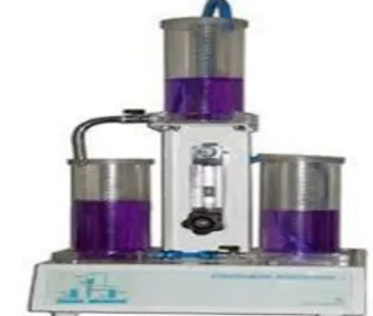
[image:1.595.349.518.568.711.2]The analysis of interacting and non-interacting system will be useful for designing and tuning the controller. The transfer function model of interacting and non-interacting system is derivative using process reaction curve method. The weighted average sum of proportional gain, integral gain and derivative gain is used to regulate the process through a final control element like position of the control valve. In Proportional –Integral-Derivative controller [2], a process parameter or variable and a set point or desired value is clearly indicated. The process parameter or variable is the system parameter that needs to be controlled, like liquid level of the tank, temperature, pressure, or flow rate, and the set point is the desired value for the parameter which to be controlled. In this proposed system, two tanks are considered in which each having identical cross section area and each system can be assumed as a second order system which are connected in interacting and in dissimilar non- interacting modes. The control system is proposed to maintain the level of the third tank at some predefined value irrespective of changes of inflow of first tank.
Fig. 1 Interacting and Non Interacting setup
Performance Analysis of Internal Model Control
and Modified Internal Model Control for Two
Tank Interacting and Non- Interacting Liquid
System
Interacting System
If any load change occurs in first tank affect, then the second tank is also affected and vice versa. When both tanks are connected in series manner, the mode is called Interacting system. The Dynamic performance of one tank is affected by the other tank, but the reverse is also true then it is Interacting System. Hence the liquids heads are reliant of each other. The control of liquid level is difficult since the liquid levels in both are dependent on each other.[1]
Non–interacting system
The tank 2 depends less on tank1 whereas the level in first tank is independent on the height on the second tank .This condition is termed as on interacting system. In general considering two systems that is if the output of the first system is not followed (or) affected by the second system is non- interacting.[1]
III. PROPOSED SYSTEM A INTERNAL MODEL CONTROL (IMC)
IMC Basic Structure:
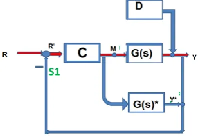
[image:2.595.332.537.340.440.2]The basic structure of IMC is shown in figure 2.The system parameters and the process model parameters are differented by the representation of “*”.
Fig. 2 IMC basic structure IMC Parameters
A variety of parameters used in the IMC basic structure shown above are as follows:
C= IMC
G(s)= actual process G(s)*= process model R= set point R’= modified set point
M= manipulated variable (controller output) D= disturbance D*= calculated new disturbance Y= measured process output Y*= process model output
New calculated disturbance: D*= (G(s) – G(s)*) M +D
Modified set-point: R’= R- D*= R- (G(s) – Gp(s)*) M – D
IMC Design Procedure
The actual process and process models are considered for designing controller. The controller C(s) is used to control the process in which the disturbances D(s) enter into the system.
Modified Internal Model Control (MIMC)
The Internal model control structure is reorganized as generalized closed loop system. The rearrangement of the controller structure improves the disturbance rejection rate and thereby increases the stability of the system. The MIMC uses the plant model as like IMC and the controller Cm is designed with help of process transfer function directly. The design of modified IMC depends only on one filter parameter for getting optimised performance with good robustness. Modified IMC procedures use an estimate for the dead time of the process. And for the process with no time delays it provides the same performance as does the IMC [6][7].
[image:2.595.76.275.458.598.2]The structure of modified internal model control is shown in figure 4.This structure is obtained simply by rearranging the summing point in IMC structure [8][9][10].
Fig. 3 Modified IMC Design IMC design for Interacting System
Transfer function of interacting system is
The internal model controller designed is
IMC design for Non-Interacting System Transfer function of non-interacting system is
(s) = inverse(Gp(s))
IV. SIMULATIONS AND DISCUSSIONS A. Interacting system
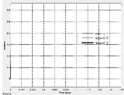
Fig. 4 Simulation result of IMC for Interacting System for different lem
[image:3.595.330.543.273.448.2]The values of the rise time, settling time, overshoot for different lem values has been tabulated in the below table
Table. 1 IMC for Interacting System for different lem Para
meters
Lem=2 Lem=1 Lem=0.5 Lem=0.2
Rise time 2.772s 1.407s 700.182ms 296.383ms Settling
time
0.26m 0.15m 0.083m 0.06m
overshoot 5.851% 4.737% 5.851% 4.737% The system is analyzed for the different lem values and the best result is obtained when the lem value is 0.2
Modified IMC for different lem values
In order to choose the best lem value, the controller has been designed for different lem values and the performance of first order system with time delay with different lem values has been compared.
[image:3.595.52.302.329.421.2]Fig. 5 Simulation result Modified IMC for Interacting The values of the rise time, settling time, overshoot for different lem values has been tabulated in the below table
Table. 2 Modified IMC for Interacting System for different lem values
Parameters Lem=2 Lem=1 Lem=0.5 Lem=0.2 Rise time 6.608s 3.318s 1.664s 667.284ms Settling time 0.333m 0.167m 0.1m 0.066m overshoot 0.505% 0.505% 0.505% 0.471%
The system is analyzed for the different lem values and the best result is obtained when the lem value is 0.2.
Comparison of controllers
The performance of the Proportional-Integral- Derivative (PID) controller, Internal Model Control (IMC) and Modified Internal Model Control (IMC) for the interacting system has been compared.
Fig. 6 Block Diagram for Interacting System Simulation result for comparison of controllers
[image:3.595.321.548.512.695.2] [image:3.595.68.275.533.691.2]Table. 3 Comparison of controllers for Interacting System
Parameters PID IMC MODIFIED
IMC Rise time 1.321s 277.251ms 659.592ms
Overshoot 10.556% 5.851% 0.505%
Settling time
[image:4.595.51.291.68.188.2]0.23m 0.04m 0.04m
Table. 4 IMC for Non-Interacting System for different lem values
Parameters Lem=2 Lem=1 Lem=0.5 Lem=0. 2 Rise time 3.601s 2.032s 1.921s 1.89 ms
Settlin g time
0.33m 0.3m 0.28m 0.26m
Overshoot 6.989% 13.068% 14.368% 10.55%
Here by choosing the best lem values we have designed first order system using model based controllers.
From the results we have inferred that the modified Internal Model Control (IMC) gives the best result for the system among others.
B. Non-Interacting System IMC for different lem values
In order to choose the best lem value, the controller has been designed for different lem values and the performance of first order system with time delay with different lem values has been compared.
Fig. 8 Simulation of IMC for Non-Interacting System for different lem values
The values of the rise time, settling time, overshoot for different lem values has been tabulated in the below table
The system is analyzed for the different lem values and the best result is obtained when the lem value is 0.2
Table. 5 Modified IMC for Non-Interacting System for
different lem values
Parameters Lem=2 Lem=1 Lem=0.5 Lem=0. 2 Rise time 5.424s 2.989s 1.921s 1.379s Settling
time
0.5m 0.417m 0.38m 0.36m
Overshoot 1.531% 5.851% 9.341% 10.556%
Modified IMC for different lem values:
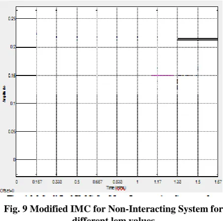
[image:4.595.320.547.246.470.2]In order to choose the best lem value, the controller has been designed for different lem values and the performance of first order system with time delaywith different lem values has been compared.
Fig. 9 Modified IMC for Non-Interacting System for different lem values
The values of the rise time, settling time, overshoot for different lem values has been tabulated in the below table The system is analyzed for the different lem values and the best result is obtained when the lem value is 0.2.
Comparison of controllers
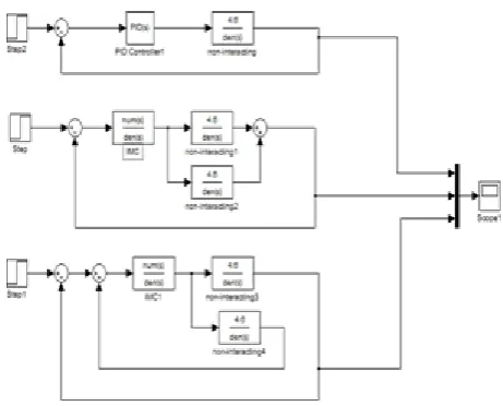
[image:4.595.66.274.487.680.2]Fig. 10 Simulink diagram for Non-Interacting System Simulation result for comparison of controllers
Fig. 11 Simulation result of Non-Interacting System Comparison of controllers for Non-Interacting System
Table. 6 Comparison of controllers for Non-Interacting System
Parameters PID IMC MODIFIED IMC
Rise time 2.862s 1.9105s 1.357s
Overshoot 12.577 %
10.556% 10.556
%
Settlin g time
0.417m 0.36m 0.33m
Here by choosing the best lem values we have designed first order system using model based controllers. From the results we have inferred that the modified Internal Model Control(IMC) gives the best result for the system among others.
V. CONCLUSION AND FUTURE SCOPE
The performance of interacting and non- interacting systems have been analyzed using PID, Internal Model Control (IMC), modified Internal Model Control (IMC). The
Internal Model Controller design procedure can be useful to resolve relatively almost any significant problems in particular at the industrial level (by means of the idea of designing a model of the actual plant process). It also provides good results to processes having significant time delays which in certainty happen when working in a real time environment. For tuning the controller the filter tuning parameter λ (lambda) value is modified, and it also compromises the various effects of discrepancies that enter the system, and thus most excellent performance is achieved. Hence, a high-quality filter structure is one for which the optimum λ value gives the greatest PID performance. From the results it is evident that the system that is controlled by using modified Internal Model Control (IMC) has the better performance. Further the systems can be implemented by IMC based tuning PID controllers, advanced controllers and intelligent controllers
REFERENCES
1. Indirapriyadharshini. J,P.Dhivya, Elayabharathi.V, Gowtham.T, V.Lokeshkannan,“ Analysis of PID controller for interacting and non- interacting system using Lab VIEW” for international journal of applied engineering research, January 2015.
2. Miss. Londhe P, Prof. Kadu C, Prof. Parvat B,“ IMC-PID controller designing for fopdt&sopdt systems”, international journal of innovative research in electrical, electronics, instrumentation and control engineering Vol. 4, Issue 5, May 2016
3. V.R.Ravi, T.Thyagarajan, M.Monika Darshini“A Multiple Model Adaptive Control Strategy for Model Predictive controller for Interacting Non Linear Systems”, International Conference on Process Automation, Control and Computing (PACC),July 2011.pp:1 – 8.
4. Rivera, D.E., M. Morari and S. Skogestad “Internal Model Control. 4. PID Controller Design,” Ind. Eng. Chem. Proc. Des. Dev., 25, 252-265 (1986).
5. Rotstein, G.E. and D.R. Lewin “Simple PI and PID Tuning for Open-Loop Unstable Systems,”Ind. Eng. Chem. Res., 30, 1864-1869 (1991).
6. A.Detchrat, V.Tipuwanporn, A.Numsomran and S.Suvikath, Member;IAENG.IMC based PID controllers design for two mass system, International Multiconference of Engineers and Computer Scientists, 2, 2012.
7. S. Skogestad, "Modeling, Identification and Control," Vol. 25, No. 2, pp. 85-120, 2004 [17] Scott Geddes ,Thesis, “Internal Model Control (IMC) of a Fruit Drying System," University of Southern Queensland,2006.
8. George Stephanopoulos, Chemical Process Control, Prentice Hall, NJ, 1984.
9. Rajesh, Arunjayankar.S, Siddharth.S.G ,“Design and implementation of IMC based PID controller for conical tank level control process” for international journal of innovative research in electrical, electronics, instrumentation and control engineering, vol 2 issue 9,September 2009.
10.Y. LEE, GS-Caltex Corp., Yeochon, Korea; S. PARK, KAIST, Daejon, Korea; and M. LEE, Yeungnam University, Kyongsan, Korea , “Consider the generalized IMC-PID method for PID
controller tuning of time-delay processes”,
Hydrocarbon Processing January 2006
11.Mohammad Shahrokhi and Alireza Zomorrodi, “Comparison of PID Controller Tuning Methods”, Department of Chemical & Petroleum Engineering Sharif University of Technology