International Journal of Innovative Technology and Exploring Engineering (IJITEE) ISSN: 2278-3075, Volume-8 Issue-12, October, 2019
Abstract—An antenna rotator is a device to buffer and rotate an under test antenna. In this paper, an automatic antenna rotator using microcontroller can be made at a minimal cost. The designed microcontroller, used to set servo motor to rotate the antenna using remote control. The rotator antenna has three movement features to help the antenna measurement. The measurement results are represented in polarization and radiation pattern graphs.
Keywords: Rotator Antenna; Microcontroller; Motor Servo; Radiation Pattern; Antenna Measurement; Polarization.
I. INTRODUCTION
Antenna measurements (validation) is a process in order to perceive the characteristics of an antenna. Tool that used to buffer and rotate an under test antenna in an antenna measurement called the antenna rotator. Antenna quality measurements for polarization and radiation pattern requires vertical and horizontal movements of the antenna. This antenna rotator is capable to decrease human errors by almost 50 percent, this tool will reduce problems occurred in manual antenna measurement cases using human help for angular displacement measurements.
Antenna rotator has two sections of rotator and controller. Servomotor MG996R is used as drive unit of the rotator. Servomotor is a device or a rotary actuator (motor) designed for applications that requires high level of accuracy for the angle shift [4]. This is because the device is designed with a closed loop feedback control system, so it can be set up to determine and ensure the angle position of the motor output shaft [10]
The controller of antenna rotator uses ATmega328P as a control tool. Arduino is an open-source platform [2] used to build and programmed a tool made with principles of electronics. This paper shows an antenna rotator has three features of a rotator rotation drive with Arduino, a potentiometer, and a push button that will makes the rotator’s rotation more accurate and efficient.
This paper will present an automatic microcontroller-based antenna rotator that is designed and realized. The antenna rotator will be used for indoor measurements, antenna rotator can rotate azimuth and elevation up to 360 degrees. The antenna rotator has three rotation features that help to measure the far field of the antenna. The antenna rotator is build and realized at a minimal cost, yet it has the ability to help movements and rotations required for
Revised Manuscript Received on August 05, 2019.
Aditama Nugraha, School of Applied Science, Telkom University, Bandung, Indonesia.
(E-mail: [email protected])
Dwi Andi Nurmantris, School of Applied Science, Telkom University, Bandung, Indonesia.
Radial Anwar, School of Applied Science, Telkom University,
antennas with the help of Arduino Uno as an antenna rotator controller.
II. METHODOLOGY 2.1. Construction
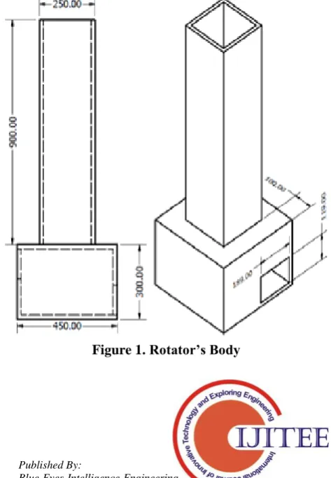
Autodesk Inventor is used to design the antenna rotator. Designs are divided to several parts of the antenna rotator. The antenna rotator is divided into rotator’s body and antenna holder. Figure 1 shows the final design of the rotator’s body. Rotator's body is a place to put the antenna holder and also as a place to store microcontroller (Arduino Uno) and other antenna rotator’s supporting electronics. Figure 2 shows the final design of the antenna holder. Antenna holder is used to put antennas that is being measured using the antenna rotator. Antenna holder has four servo motors, Servo motor is used as the drive unit of the rotator. Figure 3 shows the final design of remote control. The antennas rotator controller uses a remote control that connected to Arduino Uno. The remote control has several components used, which is cable, resistor, switch, push button and potentiometer.
[image:1.595.313.550.476.817.2]The materials used doesn’t have any side effect that would distract the process of the antenna measurements. The antenna rotator’s body height is 1.2 meters and has two kind of antenna holder which has a different size and function.
Figure 1. Rotator’s Body
Implementation of Low Cost Antenna Rotator
Based on Microcontroller
Figure 2. Antenna holder
Figure 3. Remote Control 2.2. Motor Parameters
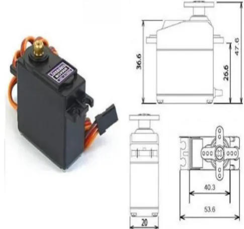
The servo motor used is MGR996R which has high torque. In order to use this servo motor, servo code or library are used to control and store all kind of servo’s
[image:2.595.311.554.76.304.2]movements command. Dimensions of the servo motor and specifications are listed in figure 4 below:
Figure 4. Motor Servo MGR996R • Weight: 55 g
• Dimension: 40.7 x 19.7 x 42.9 mm approx. • Stall torque: 9.4 kgf·cm (4.8 V ), 11 kgf·cm (6 V) • Operating speed: 0.17 s/60º (4.8 V), 0.14 s/60º (6 V) • Operating voltage: 4.8 V a 7.2 V
• Running Current 500 mA – 900 mA (6V) • Stall Current 2.5 A (6V)
• Dead band width: 5 μs
• Stable and shock proof double ball bearing design • Temperature range: 0 ºC - 55 ºC
2.3. Arduino Uno
[image:2.595.321.537.548.655.2]Arduino Uno is a microcontroller board based on the ATmega328P. It has 14 digital input/output pins (of which 6 can be used as PWM outputs), 6 analog inputs, a 16 MHz quartz crystal, an USB connection, a power jack, an ICSP header and a reset button [8].
Figure 5. Arduino Uno
International Journal of Innovative Technology and Exploring Engineering (IJITEE) ISSN: 2278-3075, Volume-8 Issue-12, October, 2019
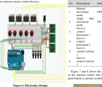
[image:3.595.68.424.75.379.2]push buttons, potentiometers, switches, Arduino Uno and resistors. All of components are assembled so that they become antenna rotator control devices.
Figure 6. Electronics Design
Parts of rotator is merged into one. Antenna holder can be replaced to match the antenna to be measured. The controller of microcontroller is connected to remote control using cable
III. RESULT AND DISCUSSION
[image:3.595.304.543.367.828.2]Autodesk Inventor is used to design the antenna rotator. The antenna rotator’s system programmed using Arduino IDE. From Table 1, we are informed about buttons that is available in the remote control. Meanwhile Table 2 informed about the variation of feature changes and assign which servo to move.
Table 1. Remote control feature
No Remote Control
Component Function Description 1 Push Button 1 Movement every 100 2 Push Button 2 Movement every 450 3 Push Button 3 Movement every 900
4 Push Button 4 Reset
5 Push Button 5 Continue
6 Potentiometer 1 Servo’s Control
Horizontal 1
7 Potentiometer 2 Servo’s Control
Horizontal 2
8 Potentiometer 3 Servo’s Control Vertical 1
9 Potentiometer 4 Servo’s Control Vertical 1
Table 2. Rotator’s feature changes and servomotor control
No Description Switch 1 Switch 2 Switch 3
1
Manual movement mode
OFF
2
Angle shift movement mode
ON
3
Servo’s control horizontal 1
ON ON
4
Servo’s control horizontal 2
OFF OFF
5
Servo’s control vertical 1
ON OFF
6
Servo’s control vertical 2
OFF ON
[image:3.595.323.542.369.547.2]Figure 7 and 8 shows the final result of the manufacture of the antenna rotator that has switch, potentiometer and push button to operate available features.
Figure 7. Antenna rotator
[image:3.595.50.288.551.728.2]Antenna rotator feature with automatic drive (Angle shift movement mode) has options of angle shift in the amount of 100, 450, and 900. Angle shifts is activated by pressing the desired angle value. Antenna rotator also has a manual control feature (live control). Using potentiometer, servomotor movement in accordance with the tempo while rotating the potentiometer.
[image:4.595.150.463.134.423.2]The test process is performed using two identical dipole antenna with 600MHz frequency, comparing the result of antenna’s measurement with or without antenna rotator with the help of human to hold the under test antenna. This test will shows that antenna rotator helps antenna measurements more accurate.
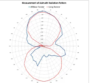
Figure 9. Measurement of Azimuth Radiation Pattern
Figure 9 shows measurement of azimuth radiation pattern using antenna and azimuth radiation pattern without antenna rotator. Radiation pattern using antenna rotator (shown with red line in polar plot) resulting a more accurate result and
[image:4.595.139.541.500.764.2]has a time efficiency to complete the measurement faster. Measurements of azimuth radiation pattern without using antenna rotator (shown with blue line in polar plot) gets less accurate results due to interference with the human body and require a longer time to complete the antenna measurements.
International Journal of Innovative Technology and Exploring Engineering (IJITEE) ISSN: 2278-3075, Volume-8 Issue-12, October, 2019
Figure 10 shows the measurement of elevation radiation pattern using rotator antenna and the measurement of elevation radiation pattern without antenna. Measurement of elevation radiation pattern using rotator antenna (shown with red line in the polar plot) gets more accurate results and has a time efficiency to complete antenna measurements
[image:5.595.121.486.125.366.2]faster. Measurement of elevation radiation pattern without using antenna rotator (shown with blue line in the polar plot) gets less accurate results due to interference with the human body and takes longer to complete antenna measurements.
Figure 11: Measurement
Figure 11 shows the measurements of polarization using antenna rotator and measurement of polarization without antenna rotator. Measurement of polarization using antenna rotator (shown with red line in polar plot) gets more accurate results and have a time efficiency to complete antenna measurements faster. Measurement of polarization without antenna rotator (shown with blue line in polar plot) gets less accurate results because manual rotation is not accurate and takes longer to complete the antenna measurement.
The test shows the performance of the antenna rotator that has been made. The antenna rotator is able to provide accurate results, on polarization and radiation pattern diagrams with the help of a rotator resulting a more accurate pattern. Rotator antenna holder can supports microstrip antennas and small wired antennas.
IV. CONCLUSION
The antenna rotator is managed to measure far field antenna such as radiation pattern measurements and antenna polarization. The antenna rotator is able to rotate 3600 horizontal (azimuth) and 3600 vertical (elevation). The antenna rotator has many features that can be controlled using a remote controller. Arduino Uno and servomotor are the controllers and the driver of antenna rotator.
V. ACKNOWLEDGEMENT
We would like to thank the
DirektoratPenelitian&PengabdianMasyarakat Telkom University for sponsoring this work through research grant Dana PenelitianUnggulan Internal 2017-2.
VI. REFERENCES
1 Alaydrus, mudrik, Antenna Prinsip&Aplikasi.
Yogyakarta : GrahaIlmu. 2011.
2 M. Banzi, Getting Started with Arduino. O'Reilly Media, Inc, 2009
3 Constantine A. Balanis, “Antenna Theory : Analysis Design Third Edition”, by John Wiley & Sons, Inc. 2005, pp. 1-24.
4 Edwin Basil Mathew et al. "Robotic arm control through
human arm movement detection using
potentiometers",International Conference on recent developments in control, Automation and power Engineering, 2015.
5 Arduino. Getting Started with Arduino and Genuino
UNO. [online].
(https://www.arduino.cc/en/Guide/ArduinoUno, 12
January 2017).
6 AsepSaefullah, DewiImmaniar, Reza Amar Juliansah.
SistemKontrol Robot
PemindahBarangMenggunakanAplikasi Android
BerbasisArduino Uno. JurnalIlmuKomputer:
Pangkalpinang. \2014
7 Autodesk Inc. 2018. Inventor Professional. [online].
(https://www.autodesk.com/education/free-software/inventor-professional, 1 November 2017). 8 Constantine A. Balanis, Modern Antenna Handbook.
Canada. John Willley& Sons, Inc. 2008.
9 Dwi P, Hendrik. PerancanganAlat Bantu
PengukuranOtomatisPolaradiasi, Polasisasi, Gain, &DirektivitasPadaAntena. Bandung : InstitutTeknologi Telkom. 2013.
11 Julie, dan Joe. 2016. Mini Satellite-Antenna Rotator. Mei
2016. Diambildari :
http://www.sarcnet.org/projects/project_rotator.html ( 14 January 2018).
12 P. Eskelinen, “A simple high-speed antenna rotator for millimeter-wave clutter measurements”. IEEE Antennas and Propagation Magazine, Volume: 47, Issue: 6, Dec. 2005.
13 Permadi, Diki. Design Antenna Rotator Based on Microcontroller to Know the Value of Elevation and Azimuth with Addition Microstrip Probe Feed Antenna 2,4 GHz. Bandung : InstitutTeknologi Telkom. 2013.
14 Wijanto, Heroe, Rama SetyaAnggaradanAgus D.