Rochester Institute of Technology
RIT Scholar Works
Theses
Thesis/Dissertation Collections
1991
Investigation of cell mapping and off-line
programming within a flexible assembly system
Marta Anna Galuga
Follow this and additional works at:
http://scholarworks.rit.edu/theses
This Thesis is brought to you for free and open access by the Thesis/Dissertation Collections at RIT Scholar Works. It has been accepted for inclusion
in Theses by an authorized administrator of RIT Scholar Works. For more information, please contact
Recommended Citation
INVESTIGATION OF CELL MAPPING AND
OFF-LINE PROGRAMMING WITHIN A
FLEXIBLE ASSEMBLY SYSTEM
Marta Anna Maria Galuga
A Thesis Submitted in Partial Fulfillment
of the Requirements for the Degree of
Master of Science
in
Mechanical Engineering
Approved by:
J.S. Torok -Thesis Advisor
Jon Freckleton
Nabil Nasr (Industrial Engineering)
Wayne Walter
Charles W. Haines (Dept. Head)
Department of Mechanical Engineering
College of Engineering
Investigation oi Cell Mapping and Off-line
Programming Within a Flexible Assembly System
I Marta A. M. Galuga prefer to be contacted prior to reproduction
(in whole or in part) of my thesis. I can be reached at the
following
address.165 Walzford Road
Rochester, New York 14622
ABSTRACT
This investigation achieves two objectives. The first
objective renders every robot on the production floor "alike"
via a single robot configuration file. The second objective
eliminates the tedious routine of
teaching
and reteaching roboticlocations on-line
by
an operator or engineer. Thefunctionality
of these software solutions is demonstrated using the AdeptOne
Scara robot, but the impact of this system is far beyond Adept.
The code listings included within this thesis are specific to the
AdeptOne controller, but the concepts developed and demonstrated
herein may be extended to any sophisticated robot controller and
ACKNQWLEDGEMEHTS
Thanks to:
The Advanced Systems
Technology
Group
at Xerox Corporation for allowing me the use of their equipment and facilities for the purposes of thisinvestigation;
Professor Torok for
being
my thesis advisorbeginning
August 1990 and continuing beyondMay
1991;
Hishelp
wastruly
appreciated.Ron Cocciara for his
help
infabricating
the shot pin locator tool.Asst. Professor Jon
Freckleton,
Professor NabilNasr,
andTABLE OF CONTENTS
List of Figures
Page
vn
List of Tables viii
1. Introduction
1.1 Robotics ^
1.2 Robots 2
1.2.1 Precision of Movement 5
1.2.1.1 Spatial Resolution 5
1.2.1.2
Accuracy
31.2.1.3
Repeatability
101.2.2 Locations and the Manual Control Pendant 13
1.2.3 Off-line
Programming
141.3 Flexible
Assembly
Systems 171.3.1 Master Cell Controller 21
1.3.2 Benefits and Drawbacks 21
1.4 Impacts of
Automating
231.4.1 The Need 23
1.4.2 The Risks 25
Page
2. Problem Description
2.1 Objective 1:
Making
Production Floor Robots29 "Alike"
via a Single Configuration File
2.2 Objective 2:
Eliminating
theNecessity
of32
Teaching
Points2.3 Limitations of the Present System 34
2.3.1 Gear Application Locations 33
2.3.2 Investigation Assumptions 42
3. Solution Implementation
3.1 Application Used 45
3.1.1 Gear
Assembly
Overview 453.1.2 End Effector Design 4g
3.2 Cell Hardware 51
3.2.1 Conveyor 51
3.2.2 AdeptOne Robot 52
3.2.2.1 Performance Specifications and 52
Operating
System3.2.2.2 V+ Functions which Enable the 53 Implemented Software Solutions
3.2.2.2.1 Frame 55
3.2.2.2.2 Shift 55
3.2.2.2.3 Trans 56
Page
3.3 Design
Considerations
for Implementation5a
3.4
Theory
of Operation3.5.1 Shot Pin Locator Probe
3.5.2 Procedure for
Teaching
Shot Pins3.5.3 Sample Contents of Robot Configuration
File
4. Conclusions & Recommendations
References
60
3.5 Robot
Configuration
Module 6i62
64
65
3.6 Pallet Configuration Module cc
3.6.1
Entering
Pallet Geometries 573.6.2
Entering
CAD Offsets Sg3.6.3 Example
Dry
Run 713.6.4 Al. locations
73
3.6.5 Calculation of Offsets without CAD Data
73
3.7 Sources of Error 75
80
85
Bibliography
37Appendices
Appendix B
Appendix C
Appendix D
Appendix E
Appendix F
Appendix G
Appendix H
Robot Configuration Software
Shot Pin Configuration Data
Gear
Assembly
Source CodeApplication
Library
Writing
ApplicationsWorld to Pallet Coordinate System Transformation Calculations
LIST OF TABLES
Table Page
2.1 Gear Application Locations
37 3.1 Sample Robot Cofiguration File
66 3.2 Shot Pin Error
CHAPTER
1INTRODUCTION
1.1
ROBOTICS
According
to Arthur J. CritchlowCI],
robotics is defined asthe collection of activities
involving
thedesign,
build,
andutilization of robots. The "official" definition
of an
industrial robot, provided
by
the Robotics Industries Association(RIA),
is the following: An industrial robot is areprogrammable, multifunctional manipulator designed to move
materials, parts,
tools,
or special devices through variableprogrammed motions for the performance of a variety of tasks.
Introduced in the early
1960s,
industrial robots were originallymeant to replace humans in operations that were
heavy,
dirty,
dangerous,
etc., thatis,
for worker protection and safety.Since
then,
the list of tasks the industrial robot can performhas increased to Include many jobs which are considered
"undesirable". Such jobs include floor scrubbing, window
washing, concrete spreading, security guarding, medical
assistance, food preparation, etc. The expectation list and
1.2 ROBOTS
Most industrial robots in use
today
are'
mounted to a base
which is bolted to the floor. The
body
is attached to thebase,
and the arm is attached to the body. At the end of the arm is a
wrist, which can be oriented in a variety of positions. A series
of joints enable relative movements between the body, arm, and
wrist. These joints usually allow either linear or rotational
movements. Together,- the
body,
arm, and wristassembly
constitute what is commonly known as the manipulator. Each
motion of the manipulator, along either the linear or rotational
axes, is controlled and regulated
by
independent actuators whichuse electric, pneumatic, or hydraulic power supplies. For
articulated arm robots, the manipulator can provide motions
similar to that of a human arm and hand.
Attached to the robot's wrist is an end effector (also
referred to as end-of-arm-tooling). The end effector is not
considered part of the robot's anatomy. The manipulator arm and
body
joints are used to position the end effector at some pointin space, while the wrist joint orients it. The end effector,
usually custom designed, is what actually enables a
general-purpose robot to perform specific tasks. Conventional end
effectors include grippers,
hooks,
scoops, vacuum cups,fingers,
power tools for
drilling,
nutdriving,
deburring,
and measuringinstruments such as dial
indicators
and lasers. After thefunctional requirements of the end effector for an application
have been specified, factors such as payload and cost are
considered.
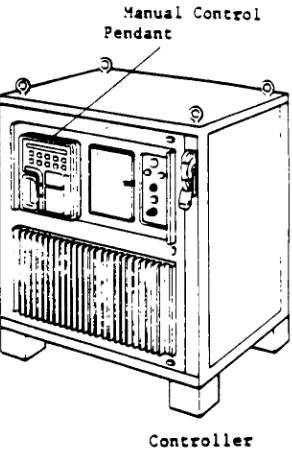
After the end effector design or selection is complete, the
robot is programmed to guide it through an application. The
robot controller is the communications, information processing,
and data storage system which initiates and terminates commands
for the movements of the robot.
Usually,
depending
on thespecific application, the controller must do more than simply
move the robot arm through a series of points in space. It must
also be able to interface with all types of equipment within it's
workcell. For example, it may have to accept input from sensors,
vision systems, bar code readers, part
feeding
equipment andother devices.
Further,
it may be required to communicate backresponses to a workcell controller in order to report data or
problems. All these
input,
output and communications functionsrequire much programming,
debugging,
andtesting
of software (inaddition to the application software) on the robot controller.
The most basic configuration for a single robotic station is
illustrated in the "System Configuration"
diagram,
Figure 1.1Programmer's Terminal
1
"^^
a
Manual Control Pendant
Controller
Manipulator
[image:14.539.331.477.124.352.2]1.2.1 PRECISION OF MOVEMENT
NOTE: The
following
material (Section 1.2.1) is provided asbackground information only. The information is compiled
primarily from
Groover,
Crithlow,
Dieter,
(see bibliography) andmy own experience in the Automation Laboratory.
Precision of movement is one of the most important measures
of performance for a robot. Precision of movement is what
ultimately determines the complexity of the task the robot will
be able to perform.
According
toGroover,
precision is afunction of three factors:
(1) Spatial resolution
(2)
Accuracy
(3)
Repeatability
1.2.1.1 SPATIAL RESOLUTION
Spatial resolution is the smallest increment of movement
into which the robot can divide its path. It depends on two
factors. These factors are the system's control resolution and
the robot's mechanical inaccuracies.
Control resolution is the controller's ability to divide the
increments that can be addressed within the controller. The bit
storage capacity of the robot's control memory governs the number
of identifiable increments available. The number of increments
(addressable points) for a particular axis is given
by
therelation:
number of increments = 2"
where n = the number of bits in the control memory. For example,
the control resolution for a one degree of freedom robot with a
sliding range of 1.0 m and a 12-bit storage capacity is 1000 mm /
21 *
, which equals 0.244 mm. A robot with several degrees of
freedom has a different control resolution for each joint of
motion.
The mechanical inaccuracies which contribute most
significantly to the robot's spacial resolution include:
1) Horizontal and vertical elastic deflection in
structural members due to the force of gravity. Heavier
workloads induce greater deflections in the robot's
mechanical
linkages,
ultimately resulting in lower local and global accuracy.2) Gear
backlash,
bearing
play, belt slack.3)
Windup
of "long" rotary members which twist undertorque.
4) Leakage of hydraulic fluids.
5)
Manufacturing
errors such as discrepancies in machiningand assembly techniques of the robot components.
direction when
heavy
loads are thrust about in the workspace.7) The condition of maintenance of the robot.
8) Thermal effects on mechanical components, etc.
9) The position of the arm within the workspace, e.g., accuracy within the work envelope tends to be worst
when the robot arm is
fully
extended and best when thearm is closest to the base.
10)
Rigidity
of the robotbase,
e.g., effects of floorvibration and compliance.
Because errors are magnified
by
large components, the larger therobot, the greater the above inaccuracies tend to become.
Suppose a programmer instructs a robot to move to a
specified start and end location using straight line motion.
Before execution of the motion, the robot controller must
calculate the sequence of individual points necessary for the
robot to follow a straight line trajectory. The number of points
into which the robot can divide its path
is,
of course, afunction of its spatial resolution. The greater the number of
increments the controller can divide its
trajectory
into,
thebetter the robot's path can be controlled. Spatial resolution
can ultimately be improved
by
increasing
the bit capacity of thecontrol memory, but this is only effective up to the point before
1.2.1.2 ACCURACY
Accuracy
refers to a robot's ability to position its wristat a desired target point within the work envelope.
Ignoring
mechanical
inaccuracies,
accuracy is defined (in its worst case)as one half of the robot's control resolution. This worst case
occurs when the target point is located
directly
between twoaddressable control points. Please reference Figure 1.2 C41.
Figure 1.2 illustrates accuracy and control resolution with
mechanical inaccuracies assumed to be zero. Because mechanical
inaccuracies are prevalent in any robotic system, Figure 1.3 [53
is a better depiction of the realistic situation. It illustrates
accuracy and spatial resolution
including
the system's mechanicalinaccuracies represented
by
a statistical distribution.When it comes to actually verifying accuracy, an accuracy of
even + 0.005 millimeters would be difficult to check. Such
verification requires precision measuring instruments capable of
measuring the position of the end effector in reference to the
robot base reference location with an overall accuracy of 0.005
millimeters under all conditions of
temperature,
acceleration,Target
point
/
Rooot
wristend
(shown
as
point)
Addressable
point
Accuracy
Control resolution
One
axisAddressable
point
Figure 1.2 [41
-Accuracy
and Control Resolution with Mechanical Inaccuracies Assumed to be ZeroTarget
point
Accuracy
Distribution
of
mechanical
inaccuracies
Spatial
resolution
One
axisFigure 1.3 [53
1.2.1.3 REPEATABILITY
Repeatability
is the robot's ability to return to orposition its wrist at a previously recorded point in space.
Accuracy
and repeatability require very different controlcapabilities.
Accuracy
requires the robot control system to beable to move precisely to an identified target point.
Repeatability
requires the robot control system to return to apreprogrammed point when commanded to do so. Under the same
conditions, repeatability is a far less stringent criterion than
accuracy. As
long
as parameters such as forces and temperaturehave not changed, one can expect successive "repeatability"
values to be the same, however poor accuracy may be. For
example, deflection of the manipulator due to gravity will cause
the same error over and over again.
Therefore,
the robot's"repeatability" is
not affected. Gear
backlash,
on the otherhand,
varies repeatability with every move of the manipulator,because the error is different at various positions within the
workspace.
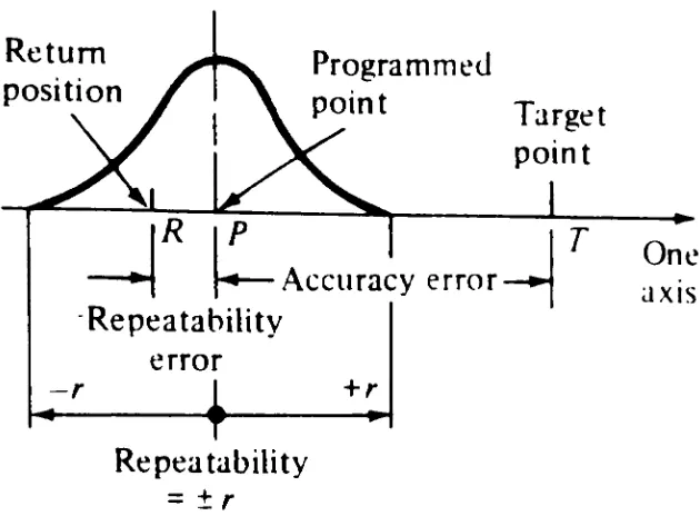
Figure 1.4 [6] illustrates both repeatability and accuracy.
In the
figure,
the robot's target destination is designated withthe letter 'T'. If the robot is commanded to move to point
T,
itactually moves to point P. The difference between points T and P
to return to point T a second
time,
it actually returns to yetanother location. This location is denoted
by
the letter 'R'.The difference between points P and R is the measure of the
robot's repeatability. The magnitude of this error (the distance
between the two points) can be determined using the
following
equation. Let points P and R be represented by:
P(Xi
,y, ,z, ) andR(x
,ye,ze )Magnitude of error = PR =
V(xe
-x, )8 + <ye y, )a + <ze
-z, )a
Subsequent repetitions of the motion demonstrate that the robot
will not continually repeat to the same position R.
Instead,
there forms a cluster of points on both sides of point P. This
point cluster
(repeatability
errors) exhibits a statisticaldistribution as indicated
by
Figure 1.4 [63.Joint inaccuracies take principal responsibility for
repeatability errors.
Individually,
each joint's repeatabilityerrors are not normally distributed.
However,
when the errorsfrom several joints are combined, the central limit theorem of
probability governs the distribution of the aggregate error [33.
The central limit theorem states that even though individual
errors come from distributions other than normal, the aggregate
error will form a normally distributed random variable.
Return
position
Programmed
point
Target
point
r
_J
If
+\
\*
Accuracy
erroRepeatability
error
r
+r
^r
Repeatability
=r
One
axis
Figure 1.4 [63
-Repeatability
andAccuracy
degrees of freedom is approximately normal.
In three-dimensional space, repeatability errors form an
ellipsoidal distribution around pre-programmed points. This
ellipsoidal shape is most
likely
attributed to the robotmanipulator's response to forces or torques exerted against it.
This response is commonly referred to as compliance. The size of
the
"repeatability
ellipsoid"is
typically
largest in the regions [image:22.539.140.455.153.385.2]of the robot.
In most cases, compliance of the robot arm is greater in one
direction than another due to the mechanical construction and
limitations of the arm. Compliance reduces the robot's precision
of movement under a load.
Again,
the deflection of the robot'sarm is much greater when carrying a
heavy
load than when carryinga light load.
Therefore,
the robot's performance is sure tosuffer if it is programmed either on or off-line, under no-load
conditions, and then later operated under loaded conditions.
Feedback devices are an integral part of the robot's control
system.
They
transmit information to the control system on theposition of various robot joints and linkages. In closed-loop
control, the system automatically measures the degree to which
the robot's movements conform to the desired response. This
feedback is then used to drive the system into conformance if
there is a discrepancy. In other words, the system is
self-correcting and the accuracy of motion is constantly monitored.
1.2.2 LOCATIONS AND THE MANUAL CONTROL PENDANT
Within this
text,
a distinction is made between a "point"and a "location". The former term refers to a point in space
defined
by
distinctX,
Y,
and Z coordinates, whereas a locationpoint. Location variables provide a means for referring to
location values using meaningful names. Within application
programs, the robot is directed to return to previously recorded
locations to either pick up parts or perform operations such as
painting, welding, and
fastening
in order to complete specifictasks or jobs.
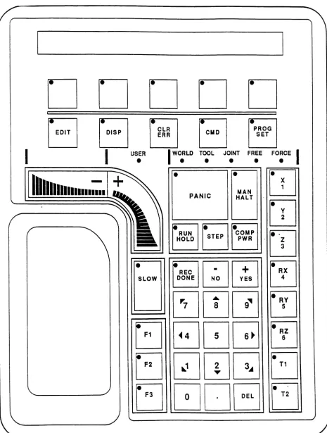
The most common way of
teaching
the robot to which locationsit must move incorporates a manual control pendant (MCP). The
MCP is a control box which hangs from a cord, like a pendant, and
contains the push buttons and switches necessary to control any
sequence of movements using the robot arm. Please reference
"Manual Control
Pendant",
Figure 1.5 [73.Pressing
the propercontrol button on the MCP applies a signal to the servo
amplifier, which in turn causes the appropriate manipulator link
to move. After the desired point is reached, the "record"
button
is pressed to store the point coordinates in the controller's
memory. The manual control pendant can control both the position
and velocity of all axes of the robot arm.
1.2.3 OFF-LINE PROGRAMMING
"Most commercial off-line programming systems are fine for
prototyping but can't be used as production tools." [83
Ronald Lumla
Intelligent Controls
Group
LeaderRobot Systems Division
Figure 1.5 [73
-Manual Control Pendant
-r-7 n
*
EDIT OISP CLRERR cuo PROGSET
I
USERI
|
WORLD TOOL JOINT FREEPANIC HALTMAN
Trun
HOLD STEP
COMP PWR
REC
DONE NO
+
YESr7
8
9*<4
5
6^
J
2
?
*A
0
DELn
RX 4
RY 5
RZ 6
T1
[image:25.540.39.504.77.692.2]Textual programming methods and a simple computer terminal
with which the programmer can input program
instructions,
allowan English-type language to establish the logic and sequence of
the work to be performed
by
the robot. An enhancement to textualprogramming is to enter a program completely off-line, without
using a teach pendant to define application locations. The
greatest advantage to off-line programming is accomplishing the
programming without ever
taking
the robot out of production.Another advantage to off-line programming is that application
programs could be run in advance to simulate the movements of the
robot without ever actually moving the manipulator.
Instead,
thecomputer
display
would simulate the movements of the robot on ascreen to assist program development.
Presently,
all methods of programming for precision assemblyoperations require the participation of the robot. If off-line
programming for assembly operations was a reality, programs could
be written using any computer then downloaded at a convenient
time to the robot. The greatest
difficulty
in off-lineprogramming is
defining
the spatial locations of positions to beused
during
the work cycle. Off-line programming of a robotrequires the ability to describe to the robot controller
appropriate locations in the robot's own coordinate system.
Though various simulation packages claim to have the
code would be useless to a robot performing precision
assembly
operations until the points
(locations)
were "touched-up" onsite. There is no way for a canned simulation model to be the
same as the robot's real world. After all, no two workcells or
robots can ever be exactly the same. There will always be some
positional error between the actual physical objects in the work
environment and the computer model. For difficult tasks such as
assembly operations, the positional errors between a simulation
and the robots world can mean the difference between success and
failure.
1.3 FLEXIBLE ASSEMBLY SYSTEMS
Manufacturing
is the processby
which raw materials areconverted into useful products. "Assembly" is the last step in
the manufacturing process. It is in this last step that
individual components are assembled either manually or
by
automatic equipment into the final product.
Assembly
anddisassembly
are both critical phases of manufacturing.Assembly,
in most cases, contributes significantly to the product's unit
manufacturing cost (UMC).
Disassembly
is a significantcontributor to the product's future servicing cost.
Because of its high degree of variability, assembly has been
automating manufacturing
functions
is closely related tofocusing
efforts on
integrating
separate operations and activities intoone interactive system. A flexible assembly system (FAS) is an
extraordinary example of just such an interactive system. It can
be modified for increased
flexibility
in order to assemblevarious types and quantities of products or subsystems
concurrently with market demand. Flexible assembly systems
utilize computer cojntrols, interchangeable and reprogrammable
feeding
devices,
coded pallets, automated guided vehicles,material
handling
and storage / retrieval systems to achievetheir flexibility.
Many
companiestoday
are replacing previouslydedicated assembly lines with such flexible systems.
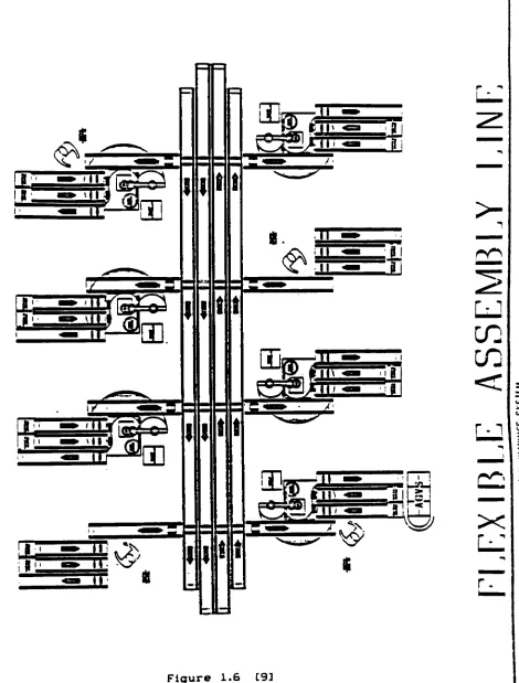
The individual stations within a FAS cell are arranged in such
a way as to yield optimum efficiency and cost as well as to
assure an orderly flow of materials, parts, and products through
the system.
Physically,
the stations can be arranged along aline,
in a U or L shape, or in a complete loop. Please referenceFigures 1.6 [93 and 1.7 [103. Figure 1.6 offers a view of a
flexible assembly line made up of multiple workcells located
around a common conveyor, whereas Figure 1.7 provides a closeup
UJ 3
C
Z
<
<^r
i-^*^
V
rjD.
i
j
i
i
j
i
i
t
t
TT
sr
'
j
uu
*n-^
.ro
cn
cn
i
X
r.
[image:29.539.44.514.79.698.2]1.3.1 MASTER CELL
CONTROLLER
The master cell controller (central computer) is vital to
the FAS cell operation. At the very
least,
the master cellcontroller must control the devices which are used for
transporting
raw materials and parts, in various stages ofcompletion, from station to station within the cell. This means
interfacing
with conveyor modules, barcode readers, as well asrobots and part
feeders,
depending
on how the cell is designed.To promote competent performance in its supervisory capacity, the
cell controller will
ideally
support a broad array of availablesoftware packages. Such packages enable statistical process /
quality control, equipment utilization reporting, job scheduling
and materials resource planning. The ability to process the
information held in various databases is what actually allows the
cell controller to make good solid decisions regarding future
cell activities based on past performance, production needs and
inventory.
1.3.2 BENEFITS AND DRAWBACKS OF FAS
Many
of the greatest benefits associated with using FAS overconventional systems are [113:
in batch sizes as small as one.
(2) Direct labor and inventories are
reduced with savings estimated at 80 to 90 percent.
(3) Machine utilization is often as high as 90 percent.
(4) Shorter lead times are required for product changeovers.
(5)
Production
is more reliable, because the system isself-correcting and product quality is uniform.
(6)
Work-in-progress
inventories arereduced.
Traditionally,
the most effective FAS applications havebeen in medium-volume (15,000
-35,000 aggregate parts per year),
batch production. High-volume (35,000 + aggregate parts per
year),
low-variety
part production is best obtained fromdedicated equipment. [123
There are drawbacks to FAS as well. In most
instances,
theeffort required to set up and maintain a FAS cell is far greater
than one could imagine.
Typically,
a FAS cell can take betweentwo and five years to install and at least six months to debug.
[133 Some of these set-up and maintenance difficulties are
attributed to the many complexities added to the systems in an
effort to make them both unmanned and flexible.
Specifically,
the difficulties are attributed to the complex control
architecture, the high speed computing necessary for real time
processing of
data,
the need for above and beyond traditionalrecovery, etc.
FAS installations are very costly,
typically
starting atwell over $1 million.
Consequently,
a thoroughcost-benefit
analysis must be conducted before a final investment decision is
made. The financial analysis must include the costs of capital,
energy, materials, and
labor,
expected markets for theproducts
being
manufactured, and anticipated fluctuations in marketdemand
and product type. .Although FAS requires
few,
ifany, machine
operators, the personnel involved with the total operation must
be trained and
highly
skilled. These personnel includemanufacturing engineers, maintenance engineers, and computer
programmers.
1.4 IMPACTS OF AUTOMATING
1.4.1 THE NEED
American
industry
is up to its assets in a globalcompetition for manufacturing supremacy, and we're
losing
more battles than we're winning.For
decades,
America led the crusade for a globalmarket economy. Now that it exists, the very
foundation of our national prosperity and economic
strength
-manufacturing - is
losing
its competitive edge. That loss has been stunning. In less than fiveyears, America went from
being
the world's greatestcreditor nation to its largest debtor. That
ignominious reversal closed hundreds of US factories
in the mid '80s as rising import rates squeezed
company after company out of the market. America's
15*/. in 1970 to 10.5% in 1987.
The implications of our competitive decline are
nationwide.
Roughly
half the jobs in America are ineither manufacturing or related service companies.
Industry
pays the nation's highest wages. Ourproductivity and savings rates ebb and flow with
manufacturing.
Every
American's prosperity dependsupon the prosperity of US industry. [143
The cost of a product is often the overriding consideration
in its marketability and general customer satisfaction.
Typically, manufacturing costs represent about 40 percent of a
product's selling price.
Assembly
costs alone make-up between 25and 50 percent of the total cost of manufacturing. In a
manufacturing facility, the percentage of workers usually
involved in assembly operations ranges from 20 to 60 percent. In
the electronics industries, some 40 to 60 percent of total wages
are paid to assembly workers. [153
A difficult challenge, posed
by
the competition, is what hasfinally
drivenindustry
to automate their manufacturingprocesses. The challenge is to improve productivity and product
quality, while simultaneously shortening product to market lead
time,
increasing
flexibility
of operation, reaching broadermarket segments across the entire price spectrum, and
decreasing
manufacturing costs in the process. Through the use of
automation, manufacturers hope to enhance their competitive
1.4.1 THE RISKS
Although automation offers exciting
benefits,
one must alsorecognize the potential
disadvantages
and limitations ofthese
technologies and their impact on the work force.
The past decade was one of disillusion for many US firms
investing
in advancedmanufacturing
technology
(AMT).
Early
robots were unreliable, flexible machining systems (FMS)installations
ended up as white elephants,, and too often nothing happened whenmanufacturers turned the
key
in turnkeys.Many
firmswere so disillusioned that
they
curtailed their rate of investment in AMT and are nowfalling
behind their Japanese counterparts. In the past five years, the Japanese have outspent US firms two to one onautomation equipment. [163
The fear of unemployment persists despite strong evidence
that advances in
technology
create more jobs-or at least
maintain the same number
-rather than eliminating them.
Although projections indicate that there will be fewer jobs
available for machine tool operators and tool and die workers,
there will be major increases in the number of computer service
technicians and maintenance electricians. The generally low
skilled, direct labor force presently engaged in traditional
manufacturing functions will shift to an indirect labor force
engaged in computer programming, information processing,
CAD/CAM,
and other high
technology
tasks essential to computer integratedmanufacturing. Development of more user
-friendly
computereasier and more manageable.
1.4.2 IMPACTS OF SUCCESSFUL
AUTOMATION
On the basis of continual advances made in various areas of
manufacturing
technology
and computer controls, one envisions thefactory
of the future as afully
automatedfacility
in whichhuman beings need not be
directly
involved with production on theshop floor. All manufacturing, material
handling,
assembly.inspection,
packaging, processing ofincoming
orders, productionplanning and scheduling, cost accounting, and various decision
making processes
(usually
performedby
management), etc. will beperformed automatically
by
computers or computer controlledmachinery and equipment. The role of humans would be confined to
supervising, performing preventative maintenance, and upgrading
machines and equipment (both hardware and software); shipping and
receiving supplies and finished products; and programming,
upgrading, and monitoring computers (both hardware and software).
Achievement of a positive, long-term "marriage" between
people and
technology
is critical for thefactory
of the futureto succeed. This contention is supported
by
a 1988 study doneby
John Krafcik of the Massachusetts Institute of Technology. In
his study of 31 automotive plants around the world, he determined
production
decisions,
is the only country to successfully linkautomation to both productivity and flexibility.
In the
U.S.,
General Motors has provided an example ofimplementing technology
with minimal attention to its relation to the workforce. Most manufacturers are awarethat,
between 1980 and1987,
General Motorsspent $42 billion on plant automation but gained
neither market share nor productivity.
Maintaining
our competitive position does not necessarily mean just
hasty
deployment of advanced technology.Technology
without people will not save Americanmanufacturers. [173
The reliability of machines, control systems, and power
supplies is also crucial to full
factory
automation. A local orgeneral breakdown in machinery, computers, power, or
communications networks will, without rapid human
intervention,
cripple production. The computer integrated
factory
of thefuture must always be capable of rerouting materials and
production flows to other machines and to the control of other
computers in case of emergencies.
Although economic considerations and trade-offs are crucial,
companies that select not to install computer integrated
operations are in jeopardy. It is a widely recognized fact
that,
in a
highly
competitive marketplace, rapid adaptability isessential to the very survival of the manufacturing organization.
Flexible assembly systems is but one of the many advanced
manufacturing technologies available to
industry
tohelp
itidentified and solved below are just the
tip
of theiceberg
ofthose needed to be addressed before flexible assembly systems
technology
can be accepted as a viable and cost effectiveCHAPTER
2PROBLEM
DESCRIPTION
References to a particular flexible assembly .systemare made
throughout the remainder of this text. This system is the FAS
III flexible assembly cell presently found in a research and
development
laboratory
at XeroxCorporation,
Webster,
New York.The design of the cell was initiated in 1984 to meet Xerox's
projected business need. This business need required
manufacturing to produce products concurrently with market demand
in a just in time (JIT) computer integrated manufacturing (CIM)
environment. The roman numeral 'III' signifies that the flexible
assembly system development project is in its third phase. It is
within this third phase that devices such as robots, conveyors,
vision systems, barcode readers, etc., were integrated to a DEC
cell controller. FAS Phase IV will be to roll the technologies
developed within the Automation
Laboratory
out onto theproduction floor.
2.1 OBJECTIVE 1: MAKING PRODUCTION FLOOR ROBOTS "ALIKE"
VIA A
SINGLE CONFIGURATION FILE
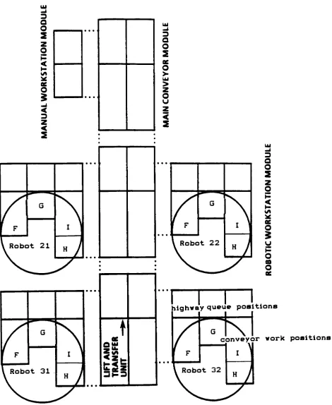
Each robotic station within the FAS III flexible assembly
cell consists of four conveyor work positions and three
highway
queue positions. Please reference the "FAS Cell
Layout"
X
Figure 2.1. In the
diagram,
the central rectangular blocksrepresent main conveyor modules. The circular shapes represent
robots and their workspaces. The conveyor work positions in
front of each robot are each labeled with the letters F
-I. The
rectangle at the
top
of the diagram illustrates a manualworkstation. This station would
typically
be used for manualrework of assemblies in case a problem is encountered at any one
of the robotic stations.
Including
this station as part of a FAScell layout allows pallets to be routed into and out of the
manual station automatically, without
interrupting
the flow ofwork through the cell. Additional robotic or manual workstations
and conveyor modules can be added or removed from the cell
without changing the system control architecture.
The coordination of the robotic stations with the main
conveyor
highway
is under control of the FAS III master cellcontroller. One of the cell controller's responsibilities is to
route pallets to the stations after the robot has requested them
for a specific job. If a robotic station goes
down,
the mastercontroller has the capability of off-loading its job to another
station. This
flexibility
implies that a particular job can bedispatched to multiple robot stations. In reality, this is not
the case. Jobs cannot be transferred from robot to robot without
additional programming or the reteaching of points. This reality
yg&jy:gpatf.sg;y* x 3 Q
O
2
eeO
$
<
Z<
2
< 3 ao
2
ocO
>o
u z<
2
I F G I|
\
Robe3t 21H
J\
1
FG
I
\
V
Robeit 22H
A
uu -J a o2
* asO
$
uP
O
eoO
f
F G I|
\
Robe>t 31H
A
?
I
I
I
L
highway queue position!
or work position!
Figure 2.1
[image:41.539.37.507.74.648.2]FAS involves a major upfront capital
investment;
therefore,
efficient machine utilization is essential. Machines and robots
cannot stand
idly
by
during lengthy
set-ups while applicationprograms are switched from one robot to another. Not
differentiating
between robots(i.e.,
possessing the capabilityto transfer jobs automatically between robots) is a necessity if
FAS scheduling is to be
truly
flexible. Thisflexibility
enablesquick response to equipment emergencies and changes in product
type and quantity.
Scheduling flexibility
is a major contributorto the "pro"
FAS manufacturing financial justification equation.
The first objective of this investigation is to make every
robot on the production floor "alike"
via a single configuration
file. This Implies
transferring
jobs from robot to robot withouthuman intervention and without
holding
up production in the cell.2.2 OBJECTIVE 2: ELIMINATING THE NECESSITY OF TEACHING POINTS
The so-called
"teaching
playback"
method is widely adopted
for positioning locations. (Please see "Locations and the Manual
Control
Pendant",
Section1.2.2,
pp., 13-15.) This method is
tedious,
time consuming and inaccurate, since decisionsconcerning the grasping and working points on assembly components
are based on human visual confirmation. Production lines must be
this purpose.
Crawling
into the robot's cage for the purpose ofteaching
points may ultimately pose a safety risk to the robotoperator or engineer.
The Production
Engineering
ResearchLaboratory
at HITACHILIMITED has quantified the time required for position
teaching
using a SCARA type robot with only four degrees-of-freedom.
They
reported their findings as follows:
Approximately
-2.9 minutes arenecessary to teach
each position point within a robotic application.
Further analysis shows that more than QOY. of the time is consumed in actual positioning and in trial /
confirmation and correction. This is because an
operator checks collisionless insertion and / or
grasping of a part at the center of an end-effector visually while moving the end-effector manually. In
some
tasks,
more than one hundred points must be taught in this manner, and therefore more than half aday
is required for teaching.Moreover,
at least oneor two re-teaching sessions per week are often
necessary for product changes.
Thus,
reduction ofteaching
time constitutes a pressing requirement, butno effective way of achieving this has been introduced
at the present time. [183
Because manufacturing production time is so expensive, one
should never have to tie up a robot within the production cell to
write an application program and teach points. Points should be
calculated, implemented, and debugged
directly
from CAD dataoff-line and away from the production floor robot. After this
process is completed, without
disrupting
the work going on in thecell, the application should be downloaded to any robot within
the manufacturing cell via an available communications line
The second objective of this investigation is to eliminate
the necessity of
teaching
points on-lineby
an operator orengineer.
2.3 LIMITATIONS OF THE PRESENT SYSTEM
Within the FAS III cell, pneumatic precision shot pin lift
units are used to repeatably position pallets on the conveyor in
front of the robots. The shot pin lift unit consists of four
pins, each pin in the corner of an
imaginary
square. Thedistance between the individual shot pins is guaranteed to +
0.076 millimeters. The orientation of the shot pin unit with
respect to the robot's coordinate system is not guaranteed. If
additional shot pin units are installed around the robot, there
is no guarantee as to the additional shot pin
units'
orientations
with respect to each other and again with respect to the robot
coordinate system.
Please reference the "Robot Workspace Diagram", Figure 2.2.
The diagram illustrates this problem in the x,y plane. The right
hand rule determines the positive z orientation of all coordinate
axes to be out of the page. The z orientation of the robot's
coordinate system is not necessarily aligned with the z
coordinates of the shot pin units located at conveyor locations G
ROBOT
WORKSPACE
Robot
workspace
and
pallet
locations
are as
follows.
B
pinptsC7,13
|_f
I
pinptsC7,23Y,
4
pinpts[7,03
pinpts[8,13f
-,H
-tpinptsCd,03
I
pinpts[8,23
F
=6
G
7
H
38
I
=9
[image:45.539.47.500.198.659.2]The discussion above describes the problem for a single robot
workspace. These problems compound in the case of a workcell
with multiple robots and multiple precision shot pin lift units.
Because "taught"
locations are specific to a particular robot and
it's workspace, software written for robot A will not work for
robot B.
2.3.1 GEAR APPLICATION LOCATIONS
The
following
data,
Table2.1,
illustrates thediscrepancy
(in millimeters) between locations "taught"
for a single
application (Section 3.1) on two different robots within the FAS
III cell. These "taught"
locations had been used previously, for
a six month period, to demonstrate robot communication with the
master cell controller in the laboratory. This same application
program is used throughout this investigation to coordinate
assembly of a gear,
housing
and clip on either robot 31 or32,
but this time without "taught" points. As indicated
by
thedata,
the discrepancies in the z and y coordinates of the locations
Table 2.1
NOTE:
X,
Y,
Z,
dimensions are recorded in millimeters.GEAR
APPLICATION
LOCATIONSLOCATION NAME
assembly. pk
Robot 31
Robot 32
105.602
-104.646
-312.605
-324.48
531.532
540.448
Difference 0.96 11.88 8.92
clear.in
Robot 31
Robot 32
-217.890
-223.641
-424.012
-414.723
532.5701
543.2064
Difference -5.75 9.29 10.64
clear.out
Robot 31
Robot 32
151.231
149.087
-485.546
-490.281
537.3458
546.1036
Difference 2.14 -4.73 8.76
cllp.pl
Robot 31
Robot 32
107.532
104.875
-314.706
-321.211
559.7991
566.1854
Difference 2.66 -6.5 6.39
cup.pk
Robot 31
Robot 32
Difference
-200.876
-198.142
2.73
-273.842
-282.643
-8.8
559.6965 565.9605
LOCATION NAME
framepts[7,l,23
Robot 31
Robot 32
Difference
pallet.refs[7, 13
Robot 31
Robot 32
Difference
pallet.refsCS, 23
LOCATION NAME
pallet.refs9, 13
Robot
31Robot
32Difference
127.7071
124.5085
-3.2
-629.318 -635.364
-6.05
508.3512
515.2829
2.3.2
INVESTIGATION
ASSUMPTIONS
(la)
Every
robotic stationwithin the FAS cell must be configured
in exactly the same way if the intention of the programmer
is to have jobs transfer from robot to robot dynamically.
That
is,
if robot A has a force sensor which is critical tothe
functionality
of a specific application, robot Brequires a force sensor as well. The
key
to understandingthis assumption is in the phrase "critical to the
functionality
of a specific application*- The softwareworks in the same manner with or without the force sensor.
The problem arises, for example, if the quality of the
product is no longer acceptable when made
by
the. robot notequipped with the force sensor. The cost trade-offs of
configuring all production floor robots in the exact same
way must be weighed on a case
by
case basisby
the designteams
implementing
the production floor systems.(lb) The robots within the FAS cell must have the same operating
system in order for the application and system software to
be able to run on all controllers.
(2) The robot must exhibit consistent positioning accuracy and
use, misuse, lack of use, wear, and encoders
getting
dirty
cannot degrade the robot's positioning accuracy beyond thelimits the station's assembly applications can tolerate.
(3) The load on the manipulator cannot cause degradation of the
robot's performance due to compliance. That
is,
themanipulator must be relatively stiff or possess low
compliance. This is especially important when one
considers the implications of programming the robot either
on or off-line under no-load conditions and then later
operating a compliant robot under loaded conditions.
(4) Software can compensate for shot pin lift units
being
slightly misoriented, but it cannot compensate for robots,
conveyors, or shot pin units cocked
badly
enough thatinsertions are no longer straight along the z axis. That
is,
a tool cannot grab a part squarely, or an instrumentdesigned to pick up a part
by
inserting
its endtop
downinto a hole cannot pick up that part because it is inserted
at an angle. This investigation assumes that the robot is
seated squarely on its base relative to the conveyor.
(5) When there is no precision lift unit available, the
that pallet location is still within the robot's physical
limitations. Although it is a very costly enhancement,
adding machine vision to each robot within the cell could
ensure
locating
parts without the risk ofdamaging
costlytooling
or components. Vision is an enhancement, it is nota necessary component for this investigation.
(6) The wear on the locator holes (on the underside of the part
pallets) never becomes severe enough to degrade the accuracy
of positioning the pallet using the precision shot pin lift
CHAPTER
3SOLUTION
IMPLEMENTATION
3.1
APPLICATION
USED3.1.1 GEAR ASSEMBLY OVERVIEW
NOTE: The gear assembly is a component that was originally
intended for a Xerox product to be launched in early 1985. The
product program was ultimately canceled in 1983.
Therefore,
thegear assembly has been obsolete for many years prior to its use
for this investigation.
The gear assembly application code is written in the V*
Adept robot programming language. The code is complete with an
abstract
detailing
what function each program performs within thegear application. Please reference the "Gear
Assembly
SourceCode"
in Appendix D for a complete program
listing
and furtherdetails.
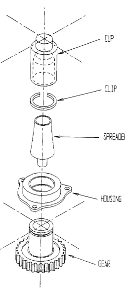
The gear assembly consists of three components: a gear,
housing,
and clip. The gear,housing,
and clip fit together asindicated in the "Gear Assembly"
diagram. Figure 3.1. The gear
pallet is always routed into and out of conveyor location G.
35. The
housing
pallet is always routed into and out of conveyorlocation I. The tooling/clip/build pallet is always routed into
and out of location H.
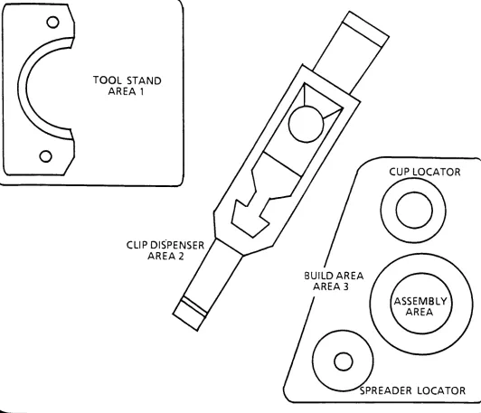
The "Tooling/Clip/Build Pallet
Diagram",
Figure3.2,
illustrates how the pallet is divided up into three distinct
areas. Area 1 contains a tool stand, area 2 a clip
dispenser,
and area 3 a build area. If the application's pneumatic end
effector is not
yet-attached to the robot arm, it is retrieved
automatically from the tool stand (area 1) prior to
beginning
thebuild process. It is automatically returned back to it's stand
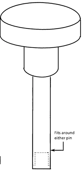
in area 1 at the end of a job. Area 3 contains the spreader and
cup needed to snap the clip onto the housing.
The program process coordinates the component assembly with
its sequence of program / function calls. Process begins
by
picking up a gear at conveyor location G (area 1) and placing it
in the build area (area 3) of the tooling/clip/build pallet at
conveyor location H. The manipulator then travels to conveyor
location I (area
1),
picks up ahousing,
returns to the buildarea (area 3) at conveyor location
H,
and then drops thehousing
onto the gear- To assist slipping the clip onto the
housing,
themanipulator picks up the
"spreader"
(still in area 3) and places
it on
top
of the housing. The manipulator now moves to area 2(still on conveyor location
H),
obtains a clip from its^^j^
CUP
CLIP
SPREADER
HOUSING
Figure
3,1
[image:57.539.143.396.78.663.2]TOOL STAND
AREA
1
CLIP
DISPENSER
AREA 2
TOP VIEW
Figure 3.2
[image:58.565.17.549.31.488.2]gear (area 3). The cup is retrieved (still in area 3) and used
to push the clip over the spreader onto the
housing
locking
thecomponents together.
Finally,
therobot replaces the cup and
spreader back to their
positioning
holes,
picksup the completed
assembly and returns it back to conveyor location G. The robot
continues to build assemblies until it completes its
job,
runsout of parts, has a forced pallet purge, crashes, the panic
button is pressed, or is interrupted
by
the cell controller.For applications to run in the complex FAS environment
requires strict adherence to programming and robot / workcell
communication guidelines. For further details on how to write
application programs for the FAS III system, please reference
Appendix F.
3.1.2 END EFFECTOR DESIGN
The end effector used for the gear assembly is an aluminum,
three-fingered,
external, mechanical grlpper. It is classifiedas an external (versus internal) gripper, because the objects it
grasps are grabbed along their outer rims. It is mechanical,
because it utilizes mechanical fingers actuated
by
a pneumaticmechanism for its grasping function. The fingers are what
actually make contact with the object.
attachable and replaceable for two basic reasons: these two
qualities allow for both wear and interchangeability.
Interchangeability
is necessary to allow different sets offingers to be used with the same gripper mechanism to accommodate
different part models.
The function of the gripper mechanism is to translate
pneumatic power from the robot into the grasping action of the
fingers against the- part. The mechanism must be able to open and
close the fingers and also exert sufficient force against the
part when closed to hold it securely.
Two specific concepts are applied to this finger design in
order to ensure secure constraint of the gear,
housing,
spreader,cup, and clip
during
assembly. The first concept is simply thephysical constriction of parts within the fingers. This is
accomplished
by
designing
the contacting surfaces of the fingersto conform with the approximate shape of the gear component
geometries (in this case, curved radii are matched with the outer
diameters of all the components). The second concept is
holding
the part
by
friction between the fingers. The fingers must applya force that is sufficient for friction to retain the part
against gravity, acceleration, and any other forces that may
arise
during
theholding
portion of the work cycle. For thisdesign,
a small piece of rubber padding is glued to the inside offriction at the areas of the fingers which contact the gear
components.
3.2 CELL HARDWARE
3.2.1 CONVEYOR
A Shuttleworth conveyor system is the primary means of
transporting
pallets andtooling
between robotic stations. It iscompletely modular so as to allow flexible assembly lines or
systems to be configured in almost any imaginable shape. (Please
see "Flexible
Assembly
Systems",
Section1.3,
pp., 17 - 18.)For
all practical purposes, from the master cell controller's point
of view, the Shuttleworth conveyor is just one more piece of
equipment within the cell to control and monitor. From the
robot's perspective, the conveyor is simply an independent piece
of equipment crowding its station. Neither the cell controller
nor the robot are dependent on whether the conveyor is a
Shuttleworth or a Bosch. The precision shot pin lift units used
to position pallets within the robot's workspace are an accessory
3.2.2 ADEPT ONE ROBOT
3.2.2.1
PERFORMANCE
SPECIFICATIONS
AND CONTROLLERAccording
to the Adept System Operations / ApplicationsTraining
Manual providedby
AdeptTechnology,
Inc.,
the AdeptOnerobots used within the FAS III cell conform to the
following
specifications:
Repeatability
Constant Temperature (X,Y): + 0.025 mm (+ 0.001 inches)
Cpnstant Temperature (X,Y,Z): + 0.051 mm (+ 0.002 inches)
Accuracy
Adept will not quote the accuracy of the AdeptOne robot;
therefore,
there is no effective guarantee as to whataccuracy can actually be achieved.
Joint 1 Rotation
Joint 2 Rotation
Joint 3 Stroke
Joint 4 Rotation
300'
maximum
294'
maximum
295 mm (11.6 inches)
554"
maximum
Power Requirements
Electrical power is supplied through the Adept controller
Compressed air @ 80 psi minimum, 120 psi maximum
V+,
a superset of the VAL-II robot programminglanguage,
isthe Adept controller operating system. It is used to run a
user-definable multitasking environment. In multitasking
environments, several programs execute at the same
time,
thusallowing asynchronous tasks to be controlled
by
separateprograms. Since today's microprocessors process instructions
serially (one instruction at a
time),
they
cannot actuallyprocess several programs at once.
However,
since processors areextremely
fast,
it seems as thoughthey
do. Adept's operatingsystem allows up to 7 tasks (1 robot task and 6 pc tasks) to run
virtually simultaneously. Examples of pc tasks include:
communicating with a host computer or another robot, performing
vision functions and calculations, controlling external
devices,
i.e.,
conveyors, partsfeeders,
etc., monitoringbinary
I/O,
andrunning an operator interface.
3.2.2.2 V* FUNCTIONS WHICH ENABLE THE IMPLEMENTED SOFTWARE
SOLUTIONS [193
NOTE: Sections 3.2.2.2 through 3.2.2.2.3 are paraphrased in part
These sections are provided as reference only. For further
details,
please consult the manual directly.A transformation is a robot-independent
representation of
the position and orientation of the robot end effector- Robot
independence is achieved
by
defining
locations in terms of aCartesian
X,
Y,
Z reference frame fixed to the base of the robot.The tool orientation is defined
by
a single angle (roll) measuredfrom the coordinate axes. It is easy to modify transformations
to change a
location,
since this method of representing locationsis so closely related to the layout of the robot workspace. For
example, to shift a location in the X
direction,
only the Xcomponent of the transformation needs to be adjusted. A minor
disadvantage in using transformations to represent locations is
the amount of computation that must be performed
by
the V*system. Whenever a transformation is used to define the
destination of a robot motion, V* must convert the Cartesian
transformation representation into a set of robot joint angles so
that it will know how to move the individual joints. The
computations for this conversion take a small amount of time, and
can introduce small location errors. The
following
V*functions
3.2.2.2.1 FRAME
Syntax
FRAME(loc_l,loc_2,loc_3,loc_4)
Function
Returns a single transformation value accurately
defining
both position and orientation of a three point plane.
Parameters
loc_l
-Transformation whose position is used to define
the Y axis endpoint of the computed frame.
loc_2
-Transformation whose position is used to define
the X axis endpoint of the computed frame.
loc_3
-Transformation whose position is used to define
where the X and Y axes of the computed frame
intersect.
loc_4
-Transformation used to indicate the reference
(origin) location of the computed frame.
3.2.2.2.2 SHIFT
Syntax
SHIFT(transformation BY x_shift, y_shift, z_shift)
Function
Returns a transformation value calculated
by
shifting the transformation parameterby
the indicated x, y, and z amounts in the world coordinate system.Parameters
transformation
x_shift
-Offset
by
which "transformation"will be shifted in the x axis.
y_shift
-Offset
by
which "transformation" will be shiftedin the y axis.
z_shift
-Offset
by
which "transformation"will be shifted
in the z axis.
3.2.2.2.3 TRANS
Syntax
TRANS(x_offset,
y_offset, z_offset,,,r_offset)Function
Returns a transformation value calculated using the
indicated x, y, z, and rotation offsets.
Pa