City, University of London Institutional Repository
Citation: Tsavdaridis, K. D. and Giaralis, A. (2011). Derivation of dynamic properties of
steel perforated Ultra Shallow Floor Beams (USFBTD) via Finite Element modal analysis and experimental verification. Paper presented at the 7th National Conference on Steel Structures, 28th - 30th September 2011, Volos, Greece.This is the unspecified version of the paper.
This version of the publication may differ from the final published
version.
Permanent repository link: http://openaccess.city.ac.uk/916/
Link to published version:
Copyright and reuse: City Research Online aims to make research
outputs of City, University of London available to a wider audience.
Copyright and Moral Rights remain with the author(s) and/or copyright
holders. URLs from City Research Online may be freely distributed and
linked to.
City Research Online: http://openaccess.city.ac.uk/ [email protected]
Tsavdaridis, KD & Giaralis, A (0028). Derivation of Dynamic Properties of Steel Perforated Ultra Shallow Floor Beams (USFB) via Finite Element Modal Analysis and Experimental Verification. Paper
presented at the 7th National Conference on Steel Structures, 28-09-2011 - 01-10-2011, Volos, Greece.
City Research Online
Original citation: Tsavdaridis, KD & Giaralis, A (0028). Derivation of Dynamic Properties of Steel Perforated Ultra Shallow Floor Beams (USFB) via Finite Element Modal Analysis and Experimental Verification. Paper presented at the 7th National Conference on Steel Structures, 28-09-2011 - 01-10-2011, Volos, Greece.
Permanent City Research Online URL: http://openaccess.city.ac.uk/1135/
Copyright & reuse
City University London has developed City Research Online so that its users may access the research outputs of City University London's staff. Copyright © and Moral Rights for this paper are retained by the individual author(s) and/ or other copyright holders. Users may download and/ or print one copy of any article(s) in City Research Online to facilitate their private study or for non-commercial research. Users may not engage in further distribution of the material or use it for any profit-making activities or any commercial gain. All material in City Research Online is checked for eligibility for copyright before being made available in the live archive. URLs from City Research Online may be freely distributed and linked to from other web pages.
Versions of research
The version in City Research Online may differ from the final published version. Users are advised to check the Permanent City Research Online URL above for the status of the paper.
Enquiries
DERIVATION OF DYNAMIC PROPERTIES OF STEEL ASYMETRIC PERFORATED ULTRA SHALLOW FLOOR BEAMS (USFBTM) VIA FINITE
ELEMENT MODAL ANALYSIS AND EXPERIMENTAL VERIFICATION
Konstantinos Daniel Tsavdaridis
Academic Fellow in Structural Engineering
School of Engineering and Mathematical Sciences, City University London London, United Kingdom
E-mail: [email protected]
Agathoklis Giaralis
Lecturer in Structural Mechanics
School of Engineering and Mathematical Sciences, City University London London, United Kingdom
E-mail: [email protected]
1. ABSTRACT
In recent years, the incorporation of asymmetric perforated ultra shallow floor beams (USFBs) constructed from advanced UB and UC profile beams in various composite floor systems has been extensively considered in practice. To date, limited research effort has been devoted to the detailed investigation of the dynamic properties of USFBs. In this paper, modal analyses of detailed FE models of various USFBs commonly used in composite floor systems developed in ANSYS are conducted to extract their dynamical properties (i.e. natural frequencies and mode shapes). Furthermore, experimental data pertaining to the standard impact test is also considered to validate the accuracy of the aforementioned FE results. In particular, a six meter long USFB beam is subject to impulsive excitation by means of an appropriately instrumented hammer. The dynamic properties obtained by processing the recorded response signals compare well vis-a-vis the corresponding results from the FE modal analysis. Finally, effective properties of USFBs which can be readily used in the definition of beam elements of constant cross-section along their longitudinal direction are derived. This constitutes an important step to facilitate the analysis and design of USFBs against dynamic loads at the serviceability limit state using standard commercial structural analysis software.
2. INTRODUCTION
their len compos induced well as slabs. In In recen utilizing welding bottom bottom minimiz concrete This co shear fo applicat plate. ‘ resisted tie-bars opening together when th steel de Fig. USFB Herein, compos common testing i the first a finite to captu experim based o several geometr constan inertial
ngth is a co site floor sys d during thei by broadban n this respec
nt years, a ne g the Ultra S g two highly
flange. Eith flange of th zing the ove e passes thro oncrete plug
orce along tions so that
Arching’ ac d by the end and service gs as the flo r with the re he beam is
cking are uti
1: Cross-sec Bs (left pane
a first step site floor st nly used bar is conducted t few flexura element (FE ure the vibr mental data w
n the above USFBs co ric propertie nt cross-secti and dynami ommonly use stems. Typic
ir service lif nd forces fro ct, their respo
ew breed of Shallow Flo y asymmetri her precast he USFB cre
erall structur ough the web g and tie-bar
the beam. A t the concre ction is occ plate conne e ducts with oor slabs ar einforcing ba
subjected to ilized for the
ction configu el) and deep
p towards th tructures is re steel USF d in the Heav al modes of v E) model of
ation behav with results FE model is ommonly us es of these U ion are deriv
c properties.
ed structura cally, such st fe by person om turbulen onse to such
composite f or Beam (U c cellular te concrete flo eating a very ral depth (F b openings, r forms a u A special en
te fully surr curred throu ctions. The hin the dept re cast. This ars and duct o axial bend e integration
uration of co decking floo
he study of undertaken FBs. For thi vy Structure vibration of this specime vior of the c
from FE mo s undertaken sed in build USFBs corres ved by relyin
.
l element in tructural sys nnel activitie nce in piping
excitations
floors have b USFB). The U
ees together oor units or
y shallow fl
Fig. 1). As th which may unique mech nd diaphrag rounds the s ugh the con
web opening th of the be s concrete p s, contribute ding. The fre n of services.
omposite floo or applicatio
the vibratio n by probin
s purpose, e es Lab at City
a simply sup en is develop considered U odal analysi n in ANSYS ding engine sponding to e
ng on specif
n long span stems are sen
es (e.g. walk g and ducting needs to be
been introduc USFB steel along the w r profiled ste loor beam co he floors ar or may not i hanism for t gm is used steel section
crete partial gs provide a eam. In-situ passing thro e to the long ee web open
. [1,2,3,4,5]
or construct on (right pan
on behavior ng into the
experimental y University pported USF ped in ANS USFB is ver is. Then, par S to obtain th eering practi equivalent E fic criteria o
light roof a nsitive to dy king, jumpin g supported
considered a
ced by ASD section is f webs resultin
eel decking onstruction re being cast
include a tie transferring for deep de n, apart from
l encasemen a passage for u concrete f ough the we gitudinal she
nings under
tion using asy nel) (ASDWe
r of the afor dynamic p l impact ham y London to FB steel spec
YS and its e rified by co rametric mo he natural fre
ice. Finally Euler-Bernou of equivalenc
as well as in ynamic loads ng, e.t.c.) as within floor at design.
DWestok Ltd fabricated by ng in a large rest on the system, thus t, the in-situ e-bar or duct
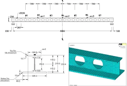
[image:4.612.101.520.379.474.2]3. EXPERIMENTAL MODAL TESTING
A simply supported bare steel Ultra Shallow Floor Beam (USFB) spanning 6m is subject to impact experimental modal testing to extract the modal characteristics of the transverse flexural modes of vibration of the beam specimen. The geometry of the beam specimen and the experimental setup are shown in Fig. 2. Three uni-axial high sensitivity shear accelerometers, henceforth acc1, acc2, and acc3, are placed on the middle of the upper flange in the mid-span and in the quarters of the 6m (positions #2,#4 and #6 as shown in
[image:5.612.108.514.393.670.2]Fig. 2). An impact hammer (model 5803A by Dytran Instruments) equipped with an embed force sensor is used to excite the transverse flexural modes of vibration of the beam specimen by hitting it downwards along the gravitational axis at the seven positions indicated in Fig. 2. Five “qualified” hits are recorded at each position. An appropriately hard hammer head was used to ensure that an adequately broadband input signal is achieved to excite modes at least up to 300Hz. A USB-9234 device by National Instruments connected to a regular PC unit is used for simultaneous data acquisition of the four channels (three output/acceleration and one input/force) and storage in ASCII format using specialized software onto the hard disk of the PC. In this manner, 30s long digital recorded signals sampled at a rate of 1024Hz are obtained from all four channels for the 35 hammer hits considered in total. This duration was found to be sufficiently long for the response transient signals to die out eliminating the need to apply an exponentially decaying time window. The stored data are then processed off-line to construct a 3-by-7 matrix H= ⎣ ⎦⎡Hij⎤ containing frequency response functions (FRFs) corresponding to location i due to an impact at location j using a custom-made script in MATLAB. The latter follows the common analysis steps used by standard FFT analysers [6,7,8].
Specifically, the raw signals are processed by a 5th order band-pass Butterworth filter with cut-off frequencies at 5Hz and at 400Hz. The filtered signals, although deterministic and non-stationary (transient) in nature, are treated as random (i.e. as samples of certain underlying stochastic processes); a common consideration in the field of impact experimental modal testing [6]. This allows for computing FRF estimates in the domain of frequencies ω by the following widely used expressions:
( )
( )
( )
1 ,
xf xx
G H
G
ω ω
ω
= (1)
and
( )
( )
( )
2 ,
xx xf
G H
G
ω ω
ω
= (2)
where Gxx and Gff are the (real) auto- power spectral density (PSD) functions of the
[image:6.612.131.485.311.556.2]acceleration and the input hammer force, respectively, and Gxf is their (complex) cross-PSD.
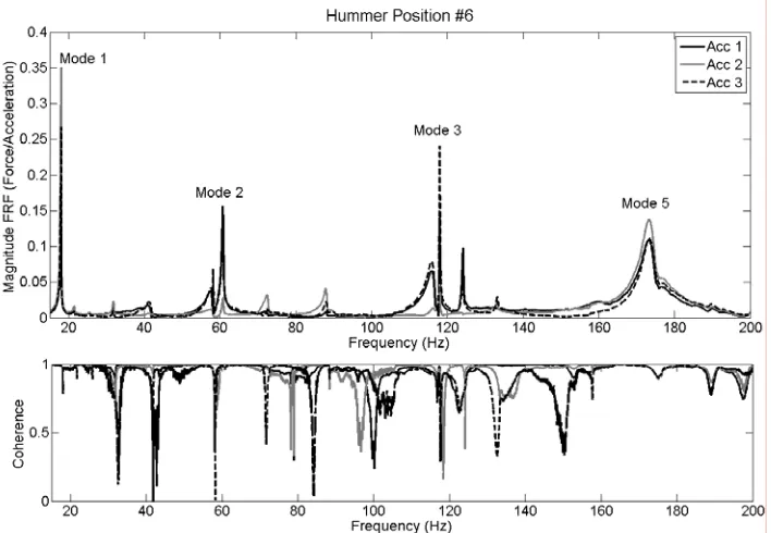
Fig. 3 : Average frequency response functions and coherence corresponding to position #6
Fig. 3 plots the magnitude of H2 estimators linearly averaged over an ensemble of five
functions corresponding to the five hammer hits at position #6 obtained from the three accelerograms (the 6th column of the H matrix constructed from the experimental data). A plot of the coherence function defined as the ratio H1/H2 is also shown to provide an
shape. However, it can be retrieved by Finite Element modal analysis as discussed in the next section. Similar observations are made to the averaged sets of FRFs corresponding to the rest of the columns of the H matrix.
Next, the FRF data around the four natural frequencies of interest indicated in
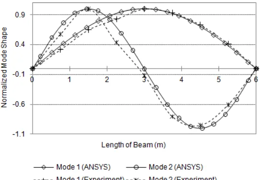
Fig. 3 are isolated and a standard SDOF circle-fitting method on the complex (Argand) plane implemented in MATLAB is employed to extract estimates of natural frequencies, damping, and modal constants (coordinates of the mode shapes) corresponding to the first three and the 5th flexural modes of vibration. The average values obtained from the total 21 FRFs of these natural frequencies and damping are collected in Table 1. Furthermore, Fig.
4 plots the first two mode shapes normalized to their peak absolute value.
Mode
Damping (%) Natural Frequency (Hz)
(in-plane flexural modes) Experimental Experimental
FE (ANSYS) FE (ANSYS) Solid beam acc 1 acc 2 acc 3 average acc 1 acc 2 acc 3 average
1st 0.98 0.98 0.98 0.98 17.954 17.948 17.948 17.950 18.184 18.449 2nd 0.94 0.80 0.98 0.91 60.705 61.135 60.699 60.846 63.565 69.628 3rd 0.23 0.24 0.23 0.23 118.03 117.93 118.02 117.99 120.74 141.87
4th - - - - - - - - 167.86 179.37
[image:7.612.177.444.401.586.2]5th 1.58 1.58 1.49 1.55 173.91 173.9 173.86 173.89 184.17 231.94
Table 1. Experimentally derived damping and natural frequencies vis-à-vis results from finite element based modal analysis.
Fig. 4 : Mode shapes normalized to their peak absolute value
4. FINITE ELEMENT MODELLING AND ANALYSES
cross sectional properties shown in Fig. 2. The accuracy of this FE model compares well against the experimental data (Table 1 and Fig. 4). Moreover, natural frequencies for the same asymmetric beam but without web openings (solid) are also included in Table 1. Evidently, it is found that the existence of the web openings influence significantly the higher modes of vibration.
4.1 Parametric Finite Element analysis
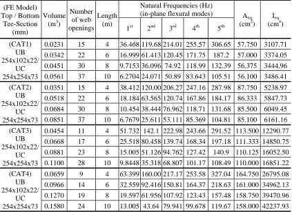
Having established a FE model for the beam specimen which compares well with the experimental modal testing, a parametric FE modal analysis is undertaken considering four commonly used in practical applications cross-sections for USFBs of four different lengths. In total, 16 models are constructed in ANSYS. Key geometric properties of the considered models are reported in the first four columns of Table 2. The first five natural frequencies and typical results from modal analysis are also reported in Table 2.
(FE Model) Top / Bottom Tee-Section
(mm)
Volume (m3)
Number of web openings
Length (m)
Natural Frequencies (Hz)
(in-plane flexural modes) Aeq (cm2)
Ieq
(cm4)
1st 2nd 3rd 4th 5th
(CAT1) UB 254x102x22/
UC 254x254x73
0.0231 15 4 36.468 119.68 214.01 255.57 306.65 57.750 3107.71
0.0342 22 6 16.999 61.413 120.45 171.75 187.2 57.000 3374.05
0.0451 30 8 9.7153 36.096 74.92 118.99 132.39 56.375 3444.96
0.0561 37 10 6.2704 24.071 50.89 83.643 105.51 56.100 3486.41
(CAT2) UB 254x102x22/
UC 254x254x73
0.0351 15 4 38.412 120.00 206.27 247.16 287.98 87.750 5238.97
0.0518 22 6 18.184 63.565 120.74 167.86 184.17 86.333 5847.73
0.0684 30 8 10.454 38.444 76.962 118.71 131.68 85.500 6049.45
0.0851 37 10 6.7679 25.611 53.111 85.369 104.81 85.100 6161.16
(CAT3) UB 254x102x22/
UC 254x254x73
0.0454 11 4 51.732 142.1 222.98 243.66 291.52 113.500 12290.77 0.0668 17 6 25.518 80.458 139.74 168.34 197.18 111.333 14850.75
0.0881 23 8 15.005 51.126 94.762 127.42 140.9 110.125 16052.50 0.1100 28 10 9.8448 35.318 68.807 101.17 108.49 110.000 16851.22 (CAT4)
UB 254x102x22/
UC 254x254x73
0.0659 9 4 63.399 160.00 217.17 253.58 327.04 164.750 26795.08
[image:8.612.96.519.263.571.2]0.0966 14 6 32.559 92.416 150.81 164.37 218.63 161.000 34962.13 0.1270 19 8 19.597 61.956 107.92 123.43 157.48 158.750 39470.96 0.1580 24 10 13.005 43.64 79.941 99.678 119.67 158.000 42237.93
Table 2. Natural frequencies from FE modal analysisand equivalent properties corresponding to Euler-Bernoulli beams of constant cross-section for various USFBs
4.2 Equivalent Geometric Properties of USFB beams
two following criteria: (i) The total mass of the equivalent prismatic beam is equal to the mass of the USFB assuming that both beams are of the same length, and (ii) The natural frequency of the first in-plane flexural mode shape of the USFB and its prismatic surrogate are equal.
In satisfying criterion (i), the Aeq is determined as the ratio of the volume over the length of the USFB. The volumes of the herein considered USFBs are reported in Table 2 along with the thus obtained Aeq. Furthermore, assuming simply supported beams, criterion (ii) is met by determining the Ieq from the expression:
2 4
1 2
4
.
eq eq
f A L I
E
ρ π
= (3)
The latter equation is derived from the well known expression of continuum dynamics for the first natural frequency (f1) of the free transverse vibration of a simply supported Euler-Bernoulli beam with mass density ρ, modulus of elasticity E, cross-sectional area Aeq, and length L. Table 2 includes values of Ieq for the various USFBs considered obtained using eq. (3) assuming ρ=7800 kg/m3
and E=200GPa corresponding to nominal steel material properties.
It is noted in passing that other criteria of equivalency can be utilized in deriving equivalent geometric properties which will generally yield different values for Aeq and Ieq [12]. In this work, the aforementioned criteria have been selected as they relate to the dynamic behavior of the USFB beams under investigation in a straightforward manner.
5. CONCLUDING REMARKS
6. REFERENCES
[1] TSAVDARIDIS KONSTANTINOS D. “Structural Performance of Perforated Steel Beams with Novel Web Openings and with Partial Concrete Encasement”,
PhD Thesis, School of Engineering and Mathematical Sciences, City University London, 2010.
[2] TSAVDARIDIS KONSTANTINOS D. and D’MELLO CEDRIC “Behaviour and Strength of Perforated Steel Beams with Novel Web Opening Shapes”, Journal of
Constructional Steel Research, 2010, Reference: JCSR3314, PII: S0143-974X(11)00106-4, DOI: 10.1016/j.jcsr.2011.04.004.
[3] TSAVDARIDIS KONSTANTINOS D., D’MELLO CEDRIC and HUO BING Y. “Shear Capacity of Perforated Concrete-Steel Ultra Shallow Floor Beams (USFB)”, 16th National Concrete Conference, 21-23 October 2009, Cyprus, Reference no: 201101, pp.159.
[4] TSAVDARIDIS KONSTANTINOS D., D’MELLO CEDRIC and HAWES MIKE “Experimental Study of Ultra Shallow Floor Beams (USFB) with Perforated Steel Sections”, Nordic Steel Construction Conference 2009 - NSCC2009, 2-4 September 2009, Malmö, Sweden, Reference no: 128, pp. 312-319.
[5] TSAVDARIDIS KONSTANTINOS D., D’MELLO CEDRIC “Experimental and Finite Element Investigation on the Vierendeel Bending of Perforated Steel Beams with Various Sizes and Novel Shapes of Web Openings”, Journal of Structural Engineering-ASCE, 2011, In print
[6] EWINS DAVID “Modal testing: Theory and Practice”, Research Studies Press
Ltd, Taunton, UK, 1995.
[7] SCHWARZ BRIAN and RICHARDSON MARK “Experimental modal analysis”,
CSI Reliability Week, Orlando, USA, 1999.
[8] BERCZYNSKI STEFAN and WROBLEWSKI TOMASZ “Experimental verification of natural vibration models of steel-concrete composite beams”,
Journal of Vibration and Control, Vol. 16, 2010, pp. 2057-2081.
[9] JAWORSKI JUSTIN and DOWELL EARL “Free vibration of a cantilevered beam with multiple steps: Comparison of several theoretical methods with experiment”, Journal of Sound and Vibration, Vol. 312, 2008, pp. 713-725.
[10] LOTFOLLAHI-YAGHIN MOHAMMAD and AHMADI HAMID “Investigation of Dynamic Properties of Cantilever Castellated Beams in Comparison with Plain-webbed Beams using White Noise Excitation”, World Applied Sciences Journal 3, Vol. 3, 2008, pp. 522-530.
[11] REN WEI-XIN, ZHAO TONG and HARIK ISSAM E. “Experimental and Analytical Modal Analysis of Steel Arch Bridge”, Journal of Structural Engineering-ASCE, Vol. 1031, 2004, DOI: 10.1061/~ASCE!0733-9445~2004!130:7~1022. [12] ZHENG TIANXIN and JI TIANJIAN “Equivalent representations of beams with
periodically variable cross-sections”, Engineering Structures, Vol. 33, 2011, pp. 706-719.
[13] EL-DARDIRY EMAD and JI TIANJIAN “Modelling of the dynamic behavior of profiled composite floors”, Engineering Structures, Vol. 28, pp. 567-579.
[14] VENGHIAC VASILE-MIRCEA and D’MELLO CEDRIC “The influence of the thickness of the slab and concrete grade on composite floors”, Publicat de