City, University of London Institutional Repository
Citation
:
Tsavdaridis, K. D. and D'Mello, C. (2011). Web buckling study of the behaviour and strength of perforated steel beams with different novel web opening shapes. Journal of Constructional Steel Research, 67(10), pp. 1605-1620. doi: 10.1016/j.jcsr.2011.04.004This is the unspecified version of the paper.
This version of the publication may differ from the final published
version.
Permanent repository link: http://openaccess.city.ac.uk/1040/
Link to published version
:
http://dx.doi.org/10.1016/j.jcsr.2011.04.004Copyright and reuse:
City Research Online aims to make research
outputs of City, University of London available to a wider audience.
Copyright and Moral Rights remain with the author(s) and/or copyright
holders. URLs from City Research Online may be freely distributed and
linked to.
City Research Online: http://openaccess.city.ac.uk/ [email protected]
Web Buckling Study of the Behaviour and Strength of Perforated Steel Beams with
Different Novel Web Opening Shapes
Konstantinos-Daniel Tsavdaridis1*, Cedric D’Mello2
1 School of Engineering and Mathematical Sciences, City University London, EC1V 0HB, UK, Office: C354, E-mail: [email protected]
2 School of Engineering and Mathematical Sciences, City University London, EC1V 0HB, UK, Office: C173, E-mail: [email protected]
ABSTRACT
This paper presents an experimental and analytical study on the behaviour of perforated steel beams with closely spaced web openings. Seven specimens including two typical cellular beams (i.e. circular web openings) and five perforated beams with novel web opening shapes were tested to investigate the failure mode and load strength of the web-post between two adjacent web openings. Fourteen numerical test specimens were developed and analysed by the finite element method and the results were compared with the full scale experiments. The effect of web opening spacing/web opening depth of web-posts was studied to investigate the effective ‘strut’ action of the web-post buckling. The effect of the web opening depth/web thickness was also studied to investigate the stability (slenderness) of the web-post subjected to vertical shear load. Two hundred and twenty-fine elastic-plastic finite element analyses were then employed in a comprehensive parametric study to propose an empirical formula which predicts the ultimate vertical shear load strength of web-posts formed from the particular web opening shapes.
Perforated beams with standard circular, hexagonal and elongated web openings are mostly used nowadays. Various non-standard web opening shapes are introduced through this paper. These new pioneering web opening shapes improve the structural performance of the perforated beams when examined under the web-post buckling failure mode. In addition, the manufacturing procedure of these non-standard web openings show great advantage in comparison with the manufacturing way of the more popular perforated beams with circular web openings (i.e. cellular beams).
Key words: Perforated steel beams, Cellular beams, Non-linear finite element analysis, Experimental tests, Web-post buckling, Novel web opening shapes, Web-post width, Vertical shear capacity, Strut model, Stability
1. Introduction
In the last decade researchers have tried to examine the web opening shapes of perforated steel sections in order to provide a better understanding of the stress distribution in the vicinity of the web openings, and to identify those that have the best structural behaviour under certain types of loading [2,3]. The aim is to provide the maximum possible web opening area for the integration of services, whilst keeping the minimum possible self weight for different types of loading.
2. Objectives
The objective of this work is to investigate and compare, through an experimental programme of work and finite element (FE) study, the behaviour of perforated steel beams with various standard and non-standard web opening shape configurations. It is therefore necessary to review existing information on web-post buckling [4,5,6] and to examine this mode of behaviour in light perforated beams with closely spaced web openings of various shapes. This work also seeks to review the design model of circular web openings and develop design models for the novel web openings, when they are closely spaced, for the complex web-post buckling failure mode.
The sub-objectives of this research are as follows:
• To observe the structural behaviour of perforated beams with closely spaced web openings in the elastic and in the plastic range.
• To examine both the load carrying capacities and the failure modes of perforated sections.
• To examine the positions of high stress concentration points in the vicinity of the web openings.
• To correlate the experimental results with FE models, and thoroughly investigate their complex structural behaviour in terms of buckling load, stress distribution and failure mode.
• To conduct an extensive FE parametric study on web-posts and then to devise a buckling model that can be used for perforated sections with various closely spaced novel web opening shapes.
3. Experimental program
3.1 Introduction
Experimental work was conducted on seven full scale steel perforated beams with various web openings in order to validate the finite element global study. Thereafter, the appropriate conditions and input data were used in the FE study to simulate the local web-post failure for all of the web opening shapes and conduct a comprehensive parametric study.
3.1 Details of specimens
adopted. The advantage of this selection is that constant shear forces are generated and hence web-post buckling failure is expected. A widely used section UB457x152x52 of steel grade S355 was chosen. Seven beams were tested in the laboratories at City University London, all with a span of 1.7m. In all seven beams the position of the web-post is the same in relation to the reactions and so the moment-shear ratio (M/V) could easily be found. The beam is symmetrical about the mid-span centre-line. Two different sets of tests were carried out.
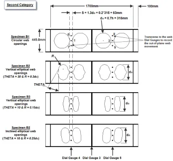
• The first category consists of specimens A1, A2 and A3. One is a circular cellular beam (A1) and the other two cellular beams with fillets of 25mm (A2) and 45mm (A3) introduced at the mid-depth of the web openings, as shown in Fig. 1. The web opening spacing was kept the same (S = 1.3do), and hence
the critical web-post width decreases as the fillet radius was increased. With the advantage of profile cutting, the bigger the radius of the fillet, the larger is the depth of the final section and hence its second moment of area.
• In the second category specimens B1, B2, B3 and B4 with different web opening shapes were investigated. These consist of one circular cellular beam (B1), two perforated sections with novel vertical elliptical web openings (B2 and B3) as well as one perforated section with novel inclined elliptical web openings (B4) (see Fig. 1). These web opening shapes consist of a combination of circular
and straight lines. The concept was arrived at using a combination of a circular and a hexagonal web opening. The potential of these two shapes was of interest. The critical web-post width was kept the same (so = 0.2do), and thus the horizontal shear capacity at the web-post was investigated for each case.
Geometric details for the design of these novel web openings shapes are given in Fig. 1 and Table 1. Further
Fig. 1a: Specimen details and gauging equipment (First Category)
[image:5.612.131.478.372.695.2]
Table 1
The details of experimental tests.
Test Specimen UB section Type Specifications Web-Post Width (mm)
Opening Area (mm2)
First Category
A1 457x152x52 Circular --- 94.5 77931
A2 457x152x52 Filleted Circular r = 25mm of fillets 48 78361 A3 457x152x52 Filleted Circular r = 45mm of fillets 15 79129 Second
Category
B1 457x152x52 Circular --- 63 77931
B2 457x152x52 Vertical Elliptical THETA = 30 and R = 0.3do 63 56452
B3 457x152x52 Vertical Elliptical THETA = 10 and R = 0.15do 63 32138
B4 457x152x52 Inclined Elliptical THETA = 10 and R = 0.25do 63 45383
3.2 Coupon tests
To determine the mechanical strength of the steel I-sections used for these tests, tensile coupon tests were carried out to the specifications and guidelines in BS EN 10002-1 [9]. Coupons were taken from two
un-yielded locations (one flange and one web) of the four steel beams tested. The yield (fy equal to
375.3MPa and 359.7MPa for web and flange/stiffener, respectively) and the ultimate stresses (fult. equal to
492.7MPa and 480.9MPa for web and flange/stiffener, respectively) were determined by averaging the results obtained from all the tensile coupon tests.
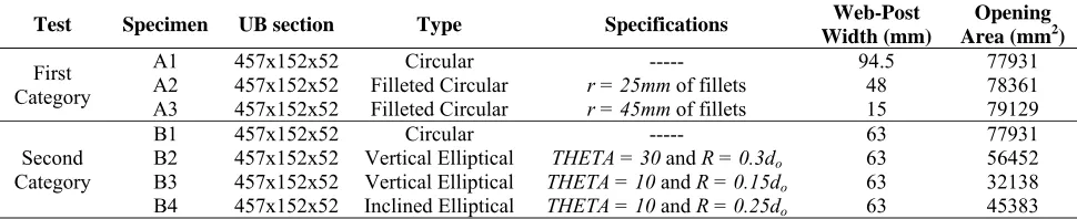
3.3 Test set-up
To ensure load distribution from supports and load and to prevent failure by lateral torsional buckling (LTB) and buckling due to compression, bearing stiffeners were utilised at supports and mid-span together with a loading plate (Fig. 2). The thickness of the stiffeners at supports is similar to the thickness of the
flange (i.e. tf = 10.9mm), while the thickness of the stiffeners at mid-span is 20mm. The loading plate was
Fig. 2: Test set-up arrangement
3.4 Test procedure
The simply supported beam was loaded at mid-span through a hydraulic jack. The load application is conducted by controlled deformation with a low displacement rate. The test procedure followed was incrementally monotonic loading to failure, followed by full unloading. Loading was continued after the ultimate load was reached in order to examine the post-elastic failure behaviour and the strain hardening slope.
The specimens were heavily gauged, as shown in Fig. 1, in an attempt to identify a primary mode of
failure i.e. either a ‘buckling load’ for the web-posts, the formation of a yield mechanism (plastic hinges), or local buckling of the flange.
In the following description of the test results, critical load, Pcr, is the load on beam of first visible
web-post buckling or rupture, which is higher than the yield load, Py. The ultimate load carrying capacity, Pult., is
the maximum load value recorded in the test, usually followed by a sudden drop of load shortly afterwards.
4 FEA study
4.1 Introduction
Global finite element analyses on seven full scale steel perforated beams with various web openings were conducted and compared with the experimental results. The aim of this global study was to validate the FE model using the experiments in order for it to be used for the parametric study, as well as to compare the results of nominal steel properties and the actual ones taken from coupon tests.
4.2 Model description
FE analyses can be found in literature [11]. It should be noted that although the specimens used in the experimental work had visible imperfections in their geometry, perfect models were used for modelling purposes. SHELL181 plastic elements were used for this work, with an average maximum size of 20mm in the vicinity of the web openings, as determined from a convergence study [7]. For specimens A2 and A3, in order to provide a better stress distribution in the vicinity of the fillets at the mid-depth of the web, much smaller elements were incorporated as such elements are more likely to be distorted. The material properties of the FE models were the same for all specimens. Linear elastic properties of the material were taken as 200GPa and 0.3 for Young’s Modulus and Poisson’s Ratio, respectively. For the plastic properties of the steel material, the average values from coupon tests were used (FEM 1 in Fig. 4). Additionally, a nominal
yield strength value (S355, fy=355MPa) was used for comparison (FEM 2 in Fig. 4). The Tangent Modulus
value was assumed to be 580MPa for both the Multi-linear Isotropic Model (MISO) with true branches (i.e. fult. is used) and the Bi-linear Isotropic Model (BISO). The Newton-Raphson solution method was used for
the analyses. For determining the post-elastic curve, the arc-length method was activated to help avoid bifurcation points and track unloading. Initial imperfections with maximum amplitude of tw/200 = 7.6/200 =
0.038 were also taken into account.
4.3 Model verification
The above model was primarily calibrated against experimental work found in the literature [1] and extensively presented in Tsavdaridis et al. [7,8]. This work led to the proposed FEA model being used to calculate the ultimate strength and load versus deformation curves for all seven perforated beams subjected to buckling load.
5 Experimental and FE results
5.1 Discussion of the results
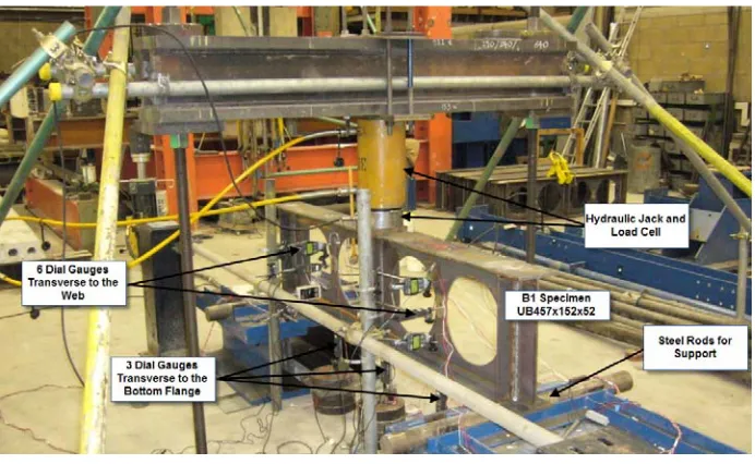
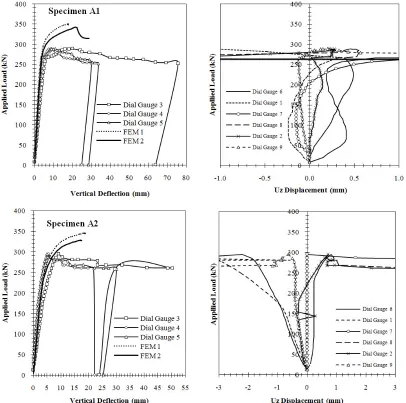
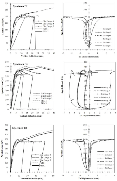
Each specimen is discussed separately. The order of yielding, mode of failure and comparison of actual to calculated FE performance is reported and a summary of the results provides overall comparison. All measurements from dial gauges are shown in Fig. 3 as they are useful when studying the web-post buckling
as shown in Fig. 4 which depicts the highly distorted web-post on every specimen after failure. Relative
predictions from the FEM models are also presented together with the schematic representation of Von-Mises stresses distribution (Fig. 4). The Von Mises yield criterion has been adopted to define the yielding
point of the steel.
Specimen A1
Web-post buckling movement of the web showed very small values up to the yield load, where the tee-sections were symmetrically displaced in opposite directions. The first visible yield was located in the “left” half-span of the beam and at a load of 257kN (i.e. Pcr). From the dial gauge readings it was seen that both
sides experience high yielding and web-post buckling by the end of the test. The ultimate load, Pult., carried
by the specimen was 289kN, whilst the beam behaves plastically with constant strain hardening to a deflection of almost 65mm.
FE models significantly overestimated the experimental values and the initiation of buckling and the ultimate load carrying capacity are 26% and 17% higher. After reaching the ultimate load carrying capacity there is a sudden loss of stiffness in the FE model, something which was observed in the tested beam too, but with less effect. Von-Mises stresses in FE model show the yielding of the compression area; the yielding of top portion of the flange and the yielding of the web extending into the flange, representing the secondary effects of shear.
Specimen A2
Very small values of web-post buckling movement were seen up to the yield load, where the tee-sections move symmetrically in opposite directions. The first visible yield was located in the “left” half-span of the beam and at a load of 267kN (i.e. Pcr). From the dial gauge readings it was seen that both sides experience
high yielding and web-post buckling at the end of the test. Following full yielding at 295kN, which is the ultimate load, Pult., a sudden drop of load was observed. However, as the specimen was loaded further, it
behaved plastically to a deflection of almost 50mm.
FE analyses diverged at a higher load than that in the test, whereas their maximum vertical deflection is much lower. Analytically, web-post buckling was observed prior to yielding, similar to that observed in the test, with the ultimate load carrying capacity being only 10% higher in FE model. A sudden drop with loss of strength was observed, with the beam behaving plastically with some strain hardening. Both sides of the beam deflected symmetrically but with different magnitude. The yielding of the top flange and that of the web extending into the flange were seen in the Von-Mises stresses contour plot. Slightly higher stresses were concentrated at the fillets, but they were not the cause of failure.
Specimen A3
From the first load steps, web movement was recorded and a web-post buckling profile was observed from the transverse web displacement readings. At a load of approximately 80kN, a second buckling mode occurred and the web moved in the opposite direction. Slight web-post movement was recorded followed by rupture of the “right” web-post at a load of 164kN (i.e. Pcr). A lower strain was observed from the
carrying capacity, Pult., of 186kN. This occurred as the top and bottom tee-sections moved together in-plane
and so provide some stiffness. Large deflection finally resulted in the decrease of the load carrying capacity and then total failure.
Modelling the structural behaviour of such a specimen was found to be challenging especially for the very narrow web-post. Failure of the model was taken as being directly after rupture of the steel web-post. It was found that the strength of the FE models is dramatically higher than the tested specimen. Finally, the top and bottom tee-sections moved together in-plane providing some stiffness, before high beam deflections and final failure occurs.
Second category includes perforated sections with circular and novel elliptical web openings:
Specimen B1
The recorded web-post movement showed very small values up to the yield load, when the tee-sections moved symmetrically in opposite directions. First visible yield was located in the “right” half-span of the beam at a load of 220kN (i.e. Pcr). Dial gauge readings showed that both sides experience high yielding and
web-post buckling at the end of the test. As the specimen was loaded, the yielding portion distorted considerably. The ultimate load carried, Pult., was 256kN, while perfectly plastic behaviour was observed
followed by strain hardening to a deflection of 27mm. Von-Mises stresses in FE model showed the yielding of the compression area and the yielding of top portion of the flange and the yielding of the web extending into the flange. This represents well the secondary effects of shear.
The results of the FE models are in good agreement with the experimental values. It can easily be seen that both web-posts were highly stressed, but with only one side highly distorted before divergence of the FE model. The final load was taken to be 275kN, slightly higher than the experimental value. A comparison between Specimen A1 and B1 showed how the web-post width affects the load carrying capacity of cellular beams.
Specimen B2
The first visible web-post movement was observed at a load of 387kN (i.e. Pcr) and the first failure mode
occurred at a load of 402kN (i.e. Pult.). Deformation of the highly distorted web-post continued until a
significant sudden fall in and a deflection of almost 50mm. Transverse web dial gauges confirmed that only the “right” side experienced web-post buckling up to the end of the test. The experiment was stopped when the “right” web-post had dramatically distorted.
stresses. Both sides of the beam experienced buckling, however only one side was highly distorted at the end of the test.
Specimen B3
The first visible web-post movement was observed at the “left” side and at a load of 387kN (i.e. Pcr).
Following the ultimate load carrying capacity of 416kN, Pult., the distortion continued as load was gradually
falling off. The transverse web dial gauges confirmed that only the “right” side experienced web-post buckling by the end of the test. The experiment was stopped when the “left” web-post had dramatically distorted at a maximum mid-span deflection of 27mm. It is worth mentioning that in this particular specimen, stresses at both web-posts moved to reasonable values.
The FE analyses showed similar behaviour in both the elastic and plastic regions. After reaching the ultimate load carrying capacity, the web became highly distorted whist the beam was gradually losing strength. Some strain hardening caused a double curvature at the plastic region. In contrast to Specimen B2 and despite the fact that the web-post width is identical (so = 0.2do = 63mm), very low stresses were
observed at the narrower part of it. Horizontal shear of the web-post is not a critical factor when such web openings are utilised. High Von-Mises stresses (i.e. plastic hinges) were concentrated at the top and bottom tee-sections. Again, the yielding of the flange and web was shown.
Specimen B4
Web-post buckling movement of both web-posts showed very small values up to the yield load, with the transverse displacement at the “right” web-post being slightly higher. The first visible yield was located in the “left” half-span of the beam and at a load of 280kN (i.e. Pcr). From dial gauges readings it was seen that
only the “left” side experienced high yielding and web-post buckling at the end of the test. On the “left” side there was high distortion, while the “right” half span no web-post buckling was observed up to a load of 327kN. The ultimate load, Pult., carried by the specimen was 346kN, with a deflection of almost 40mm.
Again, in this particular specimen, stresses at both web-posts moved to a reasonable range.
Specimen B4 is very similar to the Specimen B3 and the web-post width is the same (so = 0.2do =
5.2 Summary of the results
Table 2 summarizes all test and FE results for the yielding load, buckling (or critical) load and ultimate
loads. It is difficult to make a direct comparison of all the specimens as the new web opening configurations of the perforated sections include more than one parameter. However, some general conclusions can be drawn.
In the first category it was easily seen that when beams with circular web openings with 45mm of fillet were investigated, a very high stress concentration was observed at the notch point of the fillet. In the particular case, web-post rupture was obtained at a relatively low load level before any web-post buckling was observed. Conversely, when perforated beams with circular web openings with 25mm of fillet were examined, very similar results to the regular cellular beams (A1) were found. Although the minimum web-post width of Specimen A2 is only half the web-web-post width of the cellular beam, web and flange stresses, as well as vertical deflections and transverse web displacements, are very close. Moreover, the capacity of Specimen A2 was slightly higher, whereas the stiffness and the post-elastic strength were similar. Hence, in providing a lighter beam (A1), the overall outcome can be better. In the second category, the most important comparison is between Specimen B1 and B2 as the latter has almost 70% of the cellular’s web opening area, whilst its capacity is 1.6 times the capacity of B1. Comparing Specimens B2 and B3, it can be concluded that the critical opening length, c, and not the web opening area, affects the beam’s capacity in this case. Highly distorted web-posts are shown in Fig. 4.
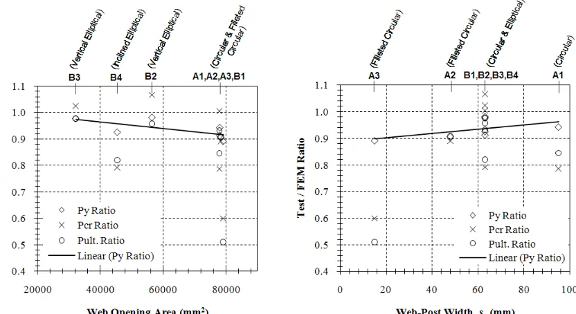
Fig. 5 shows the variation of ratio of the test loads to FEM loads plotted against the web opening areas
(left), size of web opening and the web-post widths (right). These results suggest that a satisfactory prediction with low variability has been provided by the FE method, mainly at yield load level. Py is very
well estimated by FEM for all cases with ratios close to unity and independently from the web-post width or the web openings area and shape. For higher loads, test to FE ratios are independent of the web-post area but dependent on the web-post width.
It is well known that the linear buckling prediction of thin shell is purely theoretical and it should be reduced in order to account for the influence of geometric imperfection and other defects. Initially, buckling starts at local imperfections with the formation of outer and inner waves. Geometric imperfections caused by manufacturing are the main cause of significant differences between critical buckling loads calculated using FEA and experimental buckling loads. Even very small imperfections can cause a substantial drop in the buckling load. Regarding these particular specimens, a number of manufacturing imperfections were found, especially in the perforated beams with the novel web opening shapes, due to lack of manufacturing capabilities. Other factors responsible for the deviation of the experimental and FE results are the nominal dimensions, instrumentation errors and residual stresses.
Table 2
Summary of experimental and FEM results.
Spec.
Py Pcr Pult.
Max. δ @
Pcr (mm)
*Primary Failure Mode
**Strut-Tie Angles (degrees) FE
(kN)
TEST (kN)
FE (kN)
TEST (kN)
FE (kN)
TEST (kN)
A1 265 250 327 266.5 342 288.7 5.69 WPB 132/-44
A2 204 184.5 300 298 325 298 7.09 WPB 129/-44
A3 148 131.5 274 160.5 365 186.5 8.54 Mid-Post Rupture ---
B1 204 185.5 204 203 275 255 6.55 WPB 124/-50
B2 281 276 371 375 420 402.4 10.15 WPB (1 side) 135/-43
B3 362 354 310 370 426 415 6.92 WPB (1 side) 117/-54
B4 270 250 330 290 422 350.6 5.99 WPB (1 side) 127/-46
*WPB: Web-Post Buckling
[image:15.612.113.519.67.691.2]
Fig. 4: Distorted web-posts after testing and Von-Mises stresses at failure are shown by FE contour plots
[image:17.612.97.513.316.543.2]
Fig. 5: Variations of test loads to FEM loads
6 Parametric FE study
6.1 Introduction
centre-line of adjacent web openings. The main objective was to revise the design model of circular web openings and devise design models for each of the other five novel web openings.
6.2 FE model
The FE model used in this study was based on the previous examined UB457x152x52 deep section with an opening diameter/depth, do, equal to 315mm, giving a beam opening/depth ratio of 0.7. Only the web
thickness and spacing of the web openings were varied to assess the effect on web-post capacity. A parametric study was conducted to investigate the effect of S/do ratio on the resistance of the web-post. Eight
S/do ratios in the range 1.1 to 1.8 were studied with five web thicknesses of 3.9mm, 5.0mm, 6.0mm, 7.6mm
(nominal thickness of this section) and 10.5mm (maximum possible thickness of this section), giving do/tw
ratios which varied from 30 to 80.8. The model was extended to examine the web openings presented in Fig.
1.
Four-node shell elements (SHELL181) with 6 degrees of freedom at each node were used to model the web-post. Depending on the S/do ratio and the web opening shape, different FE meshes were used to model
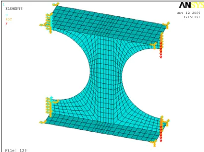
the web-posts with the element size kept the same. The magnitude of the applied load was varied manually for each case in order to achieve convergence in the initial linear stage of the analysis. The load was applied in 100 sub-steps, the size of which could be automatically varied by the software in order to achieve convergence as the solution approached the failure load. The boundary conditions used in the model are shown in Fig. 6 and Table 3. The web-flange connection was assumed to be pinned as a safe lower bound,
independent of the flange size and type of weld. In practice, some degree of fixity would exist, which increases the web buckling resistance.
[image:18.612.211.417.463.617.2]
Fig. 6: Boundary Conditions and Loading applied to the FE Model
1
File: 126 OCT 12 2009
12:51:23 ELEMENTS
Table 3
Applied boundary conditions used in the FE model.
Location UX UY UZ ROT X ROT Y ROT Z Flange (LHS) FIXED FREE FIXED FIXED FREE FIXED Web (LHS) FIXED FIXED FIXED FIXED FIXED FREE Flange (RHS) FREE FREE FIXED FIXED FIXED FIXED Web (RHS) FREE LOAD FIXED FREE FIXED FIXED
LHS/RHS: Left Hand Side/Right Hand Side
A bi-linear representation of the stress-strain curve was used. The initial elastic modulus, E, was taken as 200kN/mm2 with a reduction to 2kN/mm2 (E/100) on reaching the yield point specified as 355N/mm2. The
material model used the Von-Mises yield criterion with kinematic hardening which is suitable for most metals, including steel.
6.3 Design model
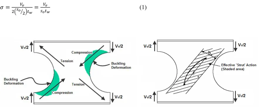
The design model was developed based on a ‘strut’ analogy in which the stability of the web was checked using buckling curves to BS 5950-1[12]. Compressive and tensile forces act across the web-post on
opposite diagonals, as illustrated in Fig. 7. Failure occurred when a local web buckle formed adjacent to the
web opening as shown by the shaded areas in Fig. 7. The compressive stress acting on the strut was
calculated using the force in the upper tee-section or half the applied vertical shear force for a symmetrically placed opening. The effective width of the web-post resisting compression was taken as the half the total width of the web-post (i.e. be = so/2) as it is shown in Fig. 8. This assumption was only used to evaluate the
compressive strength from BS and it was based on empirical observations from literature [5]. The
compressive stress acting on the strut is as follows:
(1)
Fig. 7: Typical web-post behaviour Fig. 8: Strut model of web-post buckling
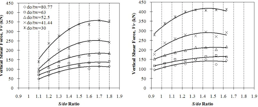
6.4 Results of the FE analysis
The vertical shear capacities obtained from the FE analyses of the web-posts are graphically represented
in Fig. 9. Improved design formulas have been developed for perforated sections with circular web openings
(A1 & B1) which cover the range of 1.1 ≤ S/do≤ 1.8 (Fig. 9). As a result of the non-linear FE parametric
study on 225 models, similar formulas have been proposed for perforated sections with the aforementioned novel web openings. Design formulas for perforated sections with vertical elliptical web openings (B2) cover the range of 0.931 ≤ S/do≤ 1.631 are shown in Fig. 9 for further comparison.
[image:20.612.93.529.214.395.2]
Fig. 9: Vertical applied shear force (kN) according to FE model (left: A1 & B1 and right: B2)
6.5 Design equations
6.5.1 Basic design model for web-post between regularly spaced web openings
The design model derived from the finite element analyses was based on a simple strut model. The strut was considered as acting diagonally across the member (Fig. 8). For perforated sections with circular web
openings; the effective length, le, of the strut was calculated as the diagonal distance across the web-post
using an effective length factor of 0.5 in the literature [5], as follows:
0.5 (2)
The slenderness, λ, of the web-post as a strut was then calculated as:
√
(3)
This value of slenderness was used to obtain the compressive strength, pc, from buckling curve “c” of BS
5950-1:2000 [12], which was appropriate for fabricated sections with maximum thickness less than 40mm.
2 (4)
6.5.2 Lower bound to web-post buckling
[image:21.612.80.397.404.584.2]The FE analyses have shown that yielding rather than buckling occurs for stockier webs. This means that web-post buckling does not occur and in some cases, the Vierendeel bending capacity will be the design check that governs rather than web-post buckling.
Fig. 11 shows the compressive strength calculated for perforated sections with circular web openings
(A1 & B1), using the established design model for all do/tw ratios plotted against the failure stress obtained
from the finite element analyses. The stress on the strut corresponding to the limiting vertical shear force determined from the maximum Vierendeel moment capacity of the tee-section is also plotted (dashed lines). The limiting vertical shear force resulting from Vierendeel bending of the top tee-section was calculated by converting the circular web opening into an equivalent rectangular web opening with a width of 0.5do and
depth do (Fig. 10). Regarding the novel web openings, suggested values for converting them to equivalent
shapes were found from the Vierendeel study on perforated beams with isolated web openings [2,7,8] and briefly presented in Table 4. The limiting vertical shear force in the top tee-section is given as follows:
(5)
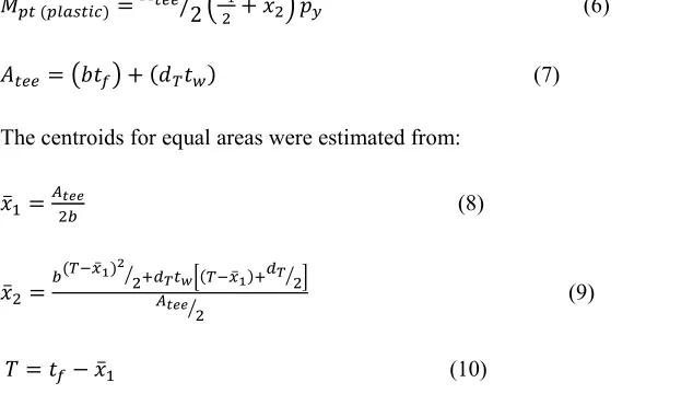
Where Mpt is the plastic moment capacity of the top tee-section and calculated as follows:
2 (6)
(7)
The centroids for equal areas were estimated from:
(8)
(9)
(10)
However, when dT/tw for the web of the tee-section exceeds the limit 9ε for a compact section (BS
5950-1:2000), the moment capacity, Mpt, was calculated using elastic properties of the section.
The FE analyses show that yielding rather than buckling occurs for stockier webs. This means that web-post buckling does not occur and the Vierendeel bending capacity is the governed design check rather than web-post buckling. For example, Fig.11 shows that the Vierendeel moment check is critical for do/tw equal to
41.44 and 30 for S/do larger than 1.3 and 1.2, respectively. The webs governed by Vierendeel bending
Fig. 10: Effective opening width and critical opening length of circular web opening
[image:22.612.103.541.252.491.2]
Table 4
Results from Vierendeel study.
Specimen Critical open. length
Vierendeel capacity should be checked for:
do/tw S/do
A1 0.5do = 41.44 = 30 > 1.3 > 1.2
A2 0.5do
= 52.5 > 1.6 = 41.44 > 1.3 = 30 > 1.2
A3 0.5do
= 52.5 > 1.6 = 41.44 > 1.3 = 30 > 1.2
B1 0.5do = 41.44 = 30 > 1.3 > 1.2
B2 0.36do = 41.44 = 30 > 1.231 > 1.131
B3 0.2do No Critical No Critical
B4 0.36do = 41.44 = 30 > 1.05 > 0.85
6.5.3 Design curve
The ratios of the vertical shear capacities evaluated by using the BS and the effective width of the
web-post assumption over the vertical shear capacities estimated by FE analyses are given in Table 5. There is
conservatism up to 79% for narrow and thin web-posts, but the level of conservatism is reduced for wider web-posts with greater web thicknesses. The shaded area indicates where the Vierendeel bending rather than the web-post buckling controls according to Fig. 11. The un-conservative stresses resulting from the basic
design model are leading to safe design for this web slenderness, as the Vierendeel bending resistance is checked separately. Table 5 is only representing the examined model with circular web openings (A1 &
B1). The solid line in Fig. 12 demonstrates the minimum compressive strength for a web-post of any web
thickness within the examined range and a certain web opening spacing. This is an empirical design curve, evaluating the compressive stress at a web-post considering both the FE results and the theoretical evaluations based on plastic moment capacity of the top tee-section.
Table 5
Ratio of vertical shear capacities (A1 & B1).
S/do
Width, so
(mm)
tw(mm)
3.9 5.0 6.0 7.6 10.5 do/tw
80.77 63 52.5 41.44 30
1.1 31.5 0.21 0.27 0.34 0.50 0.64 1.2 63 0.29 0.45 0.53 0.67 0.75 1.3 94.5 0.34 0.47 0.60 0.72 0.94 1.4 126 0.33 0.51 0.64 0.90 1.10 1.5 157.5 0.36 0.69 0.76 0.95 1.23 1.6 189 0.45 0.68 0.83 1.03 1.46 1.7 220.5 0.44 0.73 0.86 1.10 1.53 1.8 252 0.44 0.73 0.91 1.25 1.70
[image:24.612.93.541.108.507.2]
Fig. 12: Empirical design curve evaluating the compressive strength of the ‘strut’ (A1 & B1)
An empirical design formula was developed (11) and shown below while the constant factors for all examined FE models are summarised in Table 6. It is inevitable that by using this method some
overestimation was considered for certain models. Conservative but also economic results for web-posts under buckling and shear provisions were achieved.
(11)
Table 6
Design proposed factors for perforated section with novel web openings.
tw (mm) do/tw Factor A1 A2 A3 B1 B2 B3 B4
3.9 80.77
C1 160.2 181.1 57.25 207.3 160.2 63.8 143.2
C2 474 633.4 240 692.4 474 129.8 327.2
C3 208.2 422.4 160.4 462 208.2 52.63 77.12
5.0 63
C1 96.46 245 180.3 180.8 96.46 17.66 9.958
C2 316.8 802.8 657.9 619.7 316.8 99.06 99.88
C3 94.19 556.2 465.5 392.6 94.19 95.2 44.59
6.0 52.5
C1 172.4 320.3 379.4 262.8 172.4 227.9 81.88
C2 525 1104 1312 896.5 525 509.2 285.8
C3 186.6 766.8 950.5 580 186.6 36.82 22.31
7.6 41.44
C1 379.6 517 420.4 471.7 379.6 279.5 202.2
C2 1099 1768 1505 1569 1099 630.4 620.4
C3 505.6 1255 1097 1053 505.6 47.62 164.3
10.5 30
C1 477.8 683.3 847.3 617.5 477.8 498.8 454.1
C2 1390 2285 2885 2066 1390 1070 1147
C3 594 1560 2118 1371 594 125.5 333.2
6.5.4 Widely spaced web openings
For widely spaced web openings of any shape, the shear resistance can be obtained with S/do = 2.0 being
used as a cut-off limit in this analysis. For instance, in this limiting case when the effective length factor is equal to 0.5 (i.e. circular web openings) the following approach is considered:
0.5
0.5 0.5√2 0.7 (12)
2 0.6 (13)
In all cases, the shear resistance cannot exceed that given by a stress of 0.6py acting on the web-post. This
also applies to isolated circular web openings.
6.6 Position of plastic hinges and effective widths of the web openings
Table 7 and Fig. 13 illustrate the position of the plastic hinges and so the effective opening widths for
circular and elliptical web opening shapes. The positions of plastic hinges are estimated from models with widely spaced web openings. It is assumed that the hinge positions adopted for the novel elliptical web openings are non-unique while represent only the particular web opening shape with an angle (THETA) and a radius (R). A comprehensive FE study on numerous perforated sections with isolated vertical and inclined elliptical web openings has been carried out and the position of the plastic hinges has been carefully examined [7,8].
Table 7
Summary of equivalent effective widths for novel web openings.
Specimen
φ range due to mobilization
(degrees)
under Vierendeel action under Web-Post Buckling
action Max.
used φ (degrees) φ (degrees) Effective open. width φ (degrees) Effective open. width
A1/2/3 & B1
B2 B3 B4 20-29 13-22 12-22 15-30 28 22 12 21
0.25do
0.18do
0.1do
0.18do
28
17 12-14 17-45
0.25do
0.14do
0.1-0.13do
0.15-0.28do
28
22 12 21
Fig. 13: Stress concentration points, ‘strut’ models and equivalent effective opening widths
Conclusions
The tests described provide considerable information on the plastic behaviour of perforated beams with various web opening shapes. Even with a limited experimental programme involving a single standard beam configuration, it has been possible to draw a few conclusions. Failure of the specimens occurs under the combined action of shear and moment. High deformation is observed as the web-posts are subjected to high shear, accompanied by heavy distortion of the web opening. Web-post buckling occurred at loads slightly in excess of that at which deformations were first observed. No attempt has been made to present a complete analysis of the tests regarding equilibrium and stability problems and it is believed that a considerable number of further tests will be required to justify plastic beam action of these sections. The work reported here demonstrates that behaviour of perforated beams with different web opening shapes is similar.
A theoretical finite element analysis was carried out to acquire a more complete view of the web-post buckling study and the complex failure mode for perforated sections with various web opening shapes and different spacing. The conclusions from the parametric FE work conducted on 225 models are:
• Specimens A1, A2, A3, B1, B2 and B4 are governed by Vierendeel bending capacity when the web thickness is between 7.6mm < tw < 10.5mm and the web-post width is between 63mm < so < 252mm. In
general, when novel elliptical web openings are considered, the critical openings length is narrower and hence the Vierendeel capacity is high.
• From the design equations it can be seen that in general the vertical shear capacities increase as the web-post width is increased, and conversely slightly decreased when they are subjected to high Vierendeel bending forces. However, when narrow elliptical web openings are considered, the capacity only gradually increases as Vierendeel bending is not critical.
• Specimen A2 and A3 behave similarly beyond a certain web-post width, where there is better stress distribution and cut-off ‘shear’ failure is avoided. Hence, for those models, the existence of the fillets at the mid-height of the web opening with different radiuses, does not affect the vertical shear capacity of the web-posts.
In more detail, regarding the horizontal shear stresses can be concluded that:
• From the FE analysis, due to better stress distribution, the maximum shear stresses are lower in Specimens B3 and B4 for any web opening spacing and Specimen B2 when the web opening spacing is greater than 1.131do. The above stresses were found to be lower than the horizontal shear stress
resistance.
• Specimen A2 and A3 present very high shear stresses at mid-height web-post due to the existence of the fillet and especially for web opening spacing 1.3do and 1.2do. Also, Specimen B1 presents high shear
stresses at mid-height web-post.
• When relatively wide web opening spacing is considered, the maximum shear stresses move from the mid-height of the web-post towards the centroid of the axial forces, closer to the flanges.
Acknowledgments
This report has been prepared as a result of research carried out at City University London for the completeness of a Philosophy Doctorate degree. The experimental work described in this report was entirely carried out at City University laboratories. The authors would like to thank ASD Westok Ltd. group for the supply of the steel perforated specimens and the approval of the experimental structural arrangement and geometrical configurations of the specimens.
Abbreviations
be Effective width of the strut
c Critical opening length
do Vertical web opening depth (opening diameter for circular web openings)
dT Depth of the stem of the tee-section
le Effective length of the strut
Mpt Plastic moment capacity of the top tee-section
pc Compressive strength of steel in BS 5950-1
S Web opening spacing (opening pitch)
so Edge to edge spacing of the web openings (i.e. width of the web-post)
Vv Vertical shear resistance due to web-post buckling
σ Compressive stress acting on the strut
References
[1] Zaarour W, Redwood R. Web buckling in thin webbed castellated beams. Journal of Structural Engineering, Vol.122, No.8 (1996); paper 11030
[2] Chung K.F, Liu T.C.H, Ko A.C.H. Investigation on Vierendeel mechanism in steel beams with circular web openings. Journal of Constructional Steel Research, 2001, 57:467-490.
[3] Chung K.F, Liu T.C.H, Ko A.C.H. Steel beams with large web openings of various shapes and sizes: an empirical design method using a generalized moment-shear interaction. Journal of Constructional Steel Research, 2003, 59:117-1200.
[4] Ward J.K. Design of composite and non-composite cellular beams. The Steel Construction Institute, SCI Publication 100, 1990
[5] Fabsec Ltd. Design of FABSEC Cellular Beams in Non-composite and Composite Applications for both normal temperature and fire engineering conditions. Edition 2006
[6] Lawson R.M, Hicks S.J. Design of beams with large openings for services. Published by Steel Construction Institute, SCI Pre-Publication draft P355, 2006
[7] Tsavdaridis K. D. Structural performance of perforated steel beams with novel web openings and with partial concrete encasement. PhD thesis (supervised by Dr. C. D’Mello), School of Engineering and Mathematical Sciences, City University, London, 2010
[8] Tsavdaridis K. D, D’Mello C. Finite element investigation of perforated steel beams with different web opening configurations. 6th International Conference on Advances in Steel Structures (Hong Kong December
16-18, 2009) ICASS’09 Press, Hong Kong, China, 2009
[9] British Standard Institution. BS EN 10002-1:2001, Tensile testing of metallic materials. Method of test at ambient temperature. BSI 2001
[10] ANSYS version 11.0 (2009), Inc., Canonsburg, PA
[11] Johansson B, Velikovic, M. Large web openings for service integration in composite floors. Research Fund for Coal and Steel, project carried out with the financial grant of the Research Programme of the Research Fund for Coal and Steel, Coordinator RWTH, December 2006