University of Southern Queensland
Faculty of Health, Engineering & Sciences
Development of Ductile and Ultra-high Performance
Engineered Cementitious Composite (ECC) with
Lightweight Microsphere Additive
A dissertation submitted by
Mr. Gareth Grant Hess´e
in fulfilment of the requirements of
ENG4112 Research Project
towards the degree of
Bachelor of Engineering (Honours) (Civil)
Abstract
Concrete has exceptional strength when under compression; however when exposed
to tensile loading, the brittle behaviour governs its failure. Tensile strength of the
concrete can be improved by the addition of randomly dispersed short fibres within
the matrix. The allowable tensile loads carried by such composites however are not as
high as conventionally reinforced concrete. Various forms of fibres can be used within
cementitious composites, but Polyvinyl Alcohol (PVA) fibre is of particular interest
in recent research due to this high tensile strength when compared to other synthetic
fibres and its extremely high bond with the cementitious matrix.
An Engineered Cementitious Composite (ECC) is a ultra-high performance fibre
re-inforced concrete that can be produced by the inclusion of PVA fibre, in addition to
other fibre types. The design of ECCs has eventuated through the process of
mi-cromechanics and although ECCs do not achieve as high a tensile strength to that
of conventionally reinforced concrete, they do however behave in a similar manner as
isotropic materials, such as steel, by achieving strain-hardening. This is the
character-istic that distinguishes ECCs from other fibre reinforced concretes. However, in order
to achieve strain-hardening, there is a requirement for surface coating the PVA fibre
with a oil substance in order to slightly reduce the bond of the fibre / matrix interface.
This research investigates the development of a new lightweight ECC that includes
hollow glass microspheres as a lightweight additive with the inclusion of uncoated PVA
fibre. The addition of microspheres is expected to reduce the bond of fibre / matrix
interface in a similar fashion as typical PVA fibre surface coating. Two types of
mi-crospheres (Potters Industries Pty. Ltd. Sphericel 110P8 & Potters Industries Pty.
Ltd. Q-Cel 5070S) at 10%, 15% & 20% fraction volume were included within the
ii varying hollow glass microspheres were created and test specimens were prepared. The
specimens were exposed to compression, flexure and impact testing whereby the
re-sults were analysed and compared to the properties of a standard PVA-ECC in order
to assess if there was a reduction in density, an increase or maintained compressive
strength, changes in flexural properties, impact strength and whether strain-hardening
was achieved.
The outcomes suggest that the density is reduced with the inclusion of microspheres,
more so with the Q-Cel than the Sphericel. The compressive strength has minor
reduc-tions with the Sphericel micorpshere addition and may be considered negligible. The
Q-Cel however resulted in higher reductions of compressive strength. Flexural strength
and strain of the composites with uncoated PVA fibre and microsphere additions
per-formed similar to that of plain concrete, with only minor increases in flexural strength
and strain. The addition of microspheres is therefore considered not have the same
affect on the fibre bond strength as typical surface coating would. The impact testing
suggested that PVA fibre improves the impact strength at low strain rates, however at
medium to high strain rates there seems to be no greater increase in strength compared
to the plain concrete. The inclusion of microspheres to the PVA-ECC adversely affects
the impact strength of the low strain rates to match that of plain concrete. Again, no
noticeable change is witnessed to the PVA-ECC at medium to high strain rates with
University of Southern Queensland
Faculty of Health, Engineering & Sciences
ENG4111/2 Research Project
Limitations of Use
The Council of the University of Southern Queensland, its Faculty of Health,
Engineer-ing & Sciences, and the staff of the University of Southern Queensland, do not accept
any responsibility for the truth, accuracy or completeness of material contained within
or associated with this dissertation.
Persons using all or any part of this material do so at their own risk, and not at the
risk of the Council of the University of Southern Queensland, its Faculty of Health,
Engineering & Sciences or the staff of the University of Southern Queensland.
This dissertation reports an educational exercise and has no purpose or validity beyond
this exercise. The sole purpose of the course pair entitled “Research Project” is to
contribute to the overall education within the student’s chosen degree program. This
document, the associated hardware, software, drawings, and other material set out in
the associated appendices should not be used for any other purpose: if they are so used,
it is entirely at the risk of the user.
Dean
Certification of Dissertation
I certify that the ideas, designs and experimental work, results, analyses and conclusions
set out in this dissertation are entirely my own effort, except where otherwise indicated
and acknowledged.
I further certify that the work is original and has not been previously submitted for
assessment in any other course or institution, except where specifically stated.
Mr. Gareth Grant Hess´e
0050085393
Signature
Acknowledgments
I would like to thank my supervisor, Associate Professor Dr. Yan Zhuge, for her
guidance in undertaking this research. Prof. Guoxing Lu, Dr. Changjian Shen and
Dr. Dong Ruan from Swinburne University of Technology, Hawthorn, Victory, for
undertaking the impact testing and providing analysis results and PhD student Ms. Si
Chen for the sharing of information.
Furthermore, I thank Mr. Daniel Eising and Mrs. Piumika Ariyadasa for their
assis-tance in the concrete laboratory at the University of Southern Queensland. Dr. Li
Li from the University of Queensland for undertaking Scanning Electron Microscopy
(SEM) images of the samples and Potters Industries Pty. Ltd. (Australia) for the
donation of the microspheres.
In addition, a special thanks to my wife, Gaby Hess´e, for all her support and
un-derstanding during this time. Last but not least, thank you God for the insight &
understanding of this research and the provision of strength & motivation to complete
the research tasks.
Mr. Gareth Grant Hess´e
University of Southern Queensland
Contents
Abstract i
Acknowledgments v
List of Figures xii
List of Tables xv
Nomenclature xvi
Glossary of Terms xviii
Chapter 1 Introduction 1
1.1 Project Background . . . 1
1.2 Research Aims . . . 3
1.3 Research Objectives . . . 3
1.4 Conclusion . . . 5
CONTENTS vii
2.2 Fibre Reinforced Concrete . . . 6
2.2.1 Polyvinyl Alcohol (PVA) as a Fibre . . . 9
2.2.2 Micromechanics . . . 12
2.3 PVA Engineered Cementitious Composite Characteristics . . . 17
2.3.1 Compressive Characteristic . . . 18
2.3.2 Tensile Characteristic . . . 19
2.3.3 Flexural Characteristic . . . 20
2.3.4 Impact Energy Absorption Characteristic . . . 21
2.3.5 Other Characteristics . . . 21
2.4 Lightweight Engineered Cementitious Composite . . . 22
2.5 Chapter Summary . . . 25
Chapter 3 Materials and Mix designs 26 3.1 Chapter Overview . . . 26
3.2 Materials . . . 26
3.2.1 Cement . . . 27
3.2.2 Fine Sand Aggregate . . . 28
3.2.3 Water . . . 29
3.2.4 PVA Fibre . . . 29
3.2.5 Lightweight Microsphere Additive . . . 31
3.2.6 Water-Reducing Admixture . . . 33
CONTENTS viii
3.3.1 Mix Proportions . . . 34
3.3.2 Mix Design . . . 35
3.4 Chapter Summary . . . 38
Chapter 4 Experimental Investigation on LWECC 39 4.1 Chapter Overview . . . 39
4.2 Resources . . . 39
4.2.1 Specimen Preparation Equipment . . . 39
4.2.2 Specimen Testing Equipment . . . 41
4.3 Specimen Preparation . . . 45
4.4 Specimen Testing . . . 49
4.4.1 Density Test . . . 49
4.4.2 Uni-axial Compression Test . . . 50
4.4.3 Flexural Tensile Test . . . 51
4.4.4 Impact Test . . . 53
4.4.5 Microstructure Analysis . . . 53
4.5 Chapter Summary . . . 55
Chapter 5 Data Analysis and Results 57 5.1 Chapter Overview . . . 57
5.2 Data Analysis . . . 57
CONTENTS ix
5.2.2 Uni-axial Compression Analysis . . . 59
5.2.3 Flexural Tensile Analysis . . . 61
5.2.4 Impact Analysis . . . 66
5.3 Analysis Results . . . 68
5.3.1 Density Results . . . 68
5.3.2 Uni-axial Compression Results . . . 69
5.3.3 Flexural Tensile Results . . . 74
5.3.4 Impact Results . . . 80
5.3.5 Other Properties . . . 84
5.3.6 Composite Properties Summary . . . 84
5.3.7 Microstructure Analysis Results . . . 86
5.4 Chapter Summary . . . 87
Chapter 6 Conclusions and Recommendations 89 6.1 Research Conclusion . . . 89
6.2 Recommendations for Further Work . . . 91
References 93 Appendix A Project Specification 99 Appendix B Materials Data Sheets 102 B.1 Nycon PVA RECS15 Fibre . . . 103
CONTENTS x
B.3 Q-Cel 5070S Microsphere . . . 105
Appendix C Mix Design Calculations 106 C.1 Sample Batch Volume Calculations . . . 107
C.2 Mix Design Proportion 1 Calculations . . . 109
C.3 Mix Design Proportion 2 Calculations . . . 113
Appendix D Research Project Risk Assessment 116 D.1 Risk Assessment . . . 117
D.2 Risk Assessment Charts . . . 119
Appendix E Research Project Timeline 123 E.1 Timeline Discussion . . . 124
E.2 Research Project Gantt . . . 126
Appendix F MATLAB Analysis Codes 127 F.1 Density & Compression Analysis . . . 128
F.1.1 Compression Function . . . 128
F.1.2 Compression Stress-Strain Function . . . 129
F.1.3 Modulus of Elasticity Function . . . 130
F.1.4 Density & Compression Analysis Code . . . 131
F.2 Flexural Analysis . . . 146
F.2.1 4 Point Bending Flexural Stress-Deflection Function . . . 146
CONTENTS xi
F.2.3 Flexural Analysis Code . . . 148
Appendix G Specimen Data Analysis Curves 174 G.1 Compression Curves . . . 175
G.1.1 Compression Load-Displacement Curves . . . 175
G.1.2 Compression Stress-Strain Curves . . . 176
G.2 Flexural Curves . . . 177
G.2.1 4 Point Bending Load-Deflection Curves . . . 177
G.2.2 3 Point Bending Load-Deflection Curves . . . 178
G.2.3 4 Point Bending Stress-Strain Curves . . . 179
List of Figures
2.1 Typical Stress-Strain Curves . . . 8
2.2 Polyvinyl-Alcohol Chemical Structure . . . 10
2.3 PVA Fibre . . . 10
2.4 Interfacial Transition Zone . . . 11
2.5 Fibre Bridging Law Curve . . . 14
2.6 Concrete Strength Gain Curve . . . 18
3.1 Cemix GP Cement Bag . . . 27
3.2 Cemix GP Cement . . . 28
3.3 Sand Aggregate . . . 28
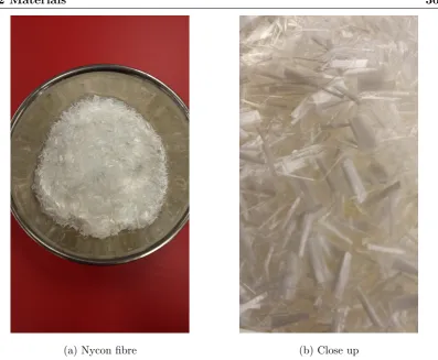
3.4 Nycon Monofilament PVA RECS15 Fibre . . . 30
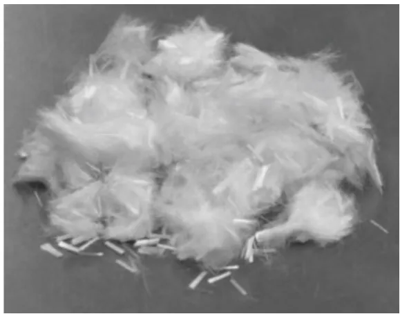
3.5 Hollow Glass Microspheres . . . 31
3.6 HRWR Admixture . . . 34
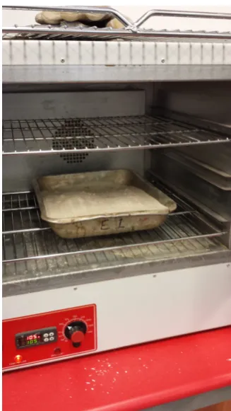
4.1 Small Industrial Oven . . . 40
4.2 Dynapac Vibrating Plate & Sieves . . . 40
LIST OF FIGURES xiii
4.4 Impact 3000 kN Compression Machine . . . 42
4.5 Impact 100 kN Flexure Frame . . . 43
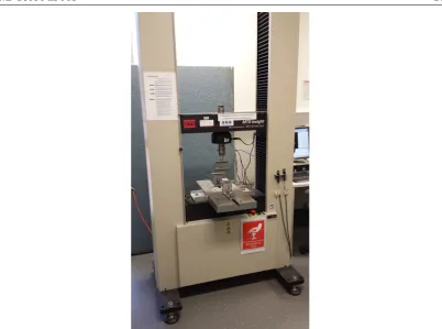
4.6 MTS Insight-100 Electromechanical Universal Machine . . . 44
4.7 Split-Hopkinson Pressure Bar (SHPB) . . . 45
4.8 Oven Drying Sand . . . 46
4.9 Sieves & Sieved Sand . . . 47
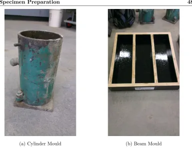
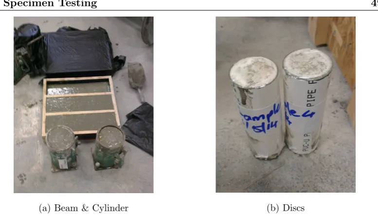
4.10 Cylinder and Beam Mould . . . 48
4.11 Fresh Cylinder, Beam & Disc Samples . . . 49
4.12 Cylinder, Beam & Disc Test Specimens . . . 50
4.13 Three (3) Point Bending Test . . . 52
4.14 Split-Hopkinson Pressure Bar (SHPB) Set-up . . . 53
5.1 Four (4) Point Bending Configuration . . . 62
5.2 Three (3) Point Bending Configuration . . . 63
5.3 Composite Densities Chart . . . 68
5.4 Compression Stress-Strain Curves . . . 70
5.5 Compressive Strength Charts . . . 71
5.6 Worn Compression Capping Plate . . . 73
5.7 Modulus of Elasticity Charts . . . 74
5.8 Flexural Load-Deflection Curves . . . 75
5.9 Flexural Stress-Strain Curves & Charts . . . 76
LIST OF FIGURES xiv
5.11 Impact Stress-Strain Curves . . . 81
5.12 Scanning Electron Microscopy (SEM) Images . . . 86
G.1 Compression Load-Displacement Curves . . . 175
G.2 Compression Stress-Strain Curves . . . 176
G.3 Four (4) Point Bending Load-Deflection Curves . . . 177
G.4 Three (3) Point Bending Load-Deflection Curves . . . 178
G.5 Four (4) Point Bending Stress-Strain Curves . . . 179
List of Tables
2.1 Fibre Properties . . . 12
2.2 PVA-ECC Mix Proportions . . . 17
2.3 Engineered Cementitious Composite (ECC) Properties . . . 18
3.1 Nycon RECS15 PVA Fibre Properties . . . 30
3.2 Hollow Glass Microsphere Properties . . . 32
3.3 Research Project Mix Proportions . . . 34
3.4 Mix Proportions 1 – Mix Designs . . . 36
3.5 Mix Proportions 2 – Mix Designs . . . 37
5.1 Properties Summary of Research Project Composites . . . 85
Nomenclature
A Area of the surface interface of steel bars to disc specimen (i.e. the cross sectional area the steel bars)
Ac Cross sectional area of cylinder specimen
As Cross sectional area of a disc specimen
Bb Width of beam specimen
c0 Elastic wave speed of steel
Db Depth of beam specimen
Dc Diameter of cylinder specimen
E Young’s modulus of elasticity for steel Ec Young’s modulus of elasticity for concrete
˙
Ec Average Young’s modulus of elasticity for a mix design
fc.f First crack strength of a beam specimen
fc.f0 Mean first crack strength for a mix design h Height of cylinder specimen
L Beam span or support centres Lb Length of beam specimen
Ls Length of the disc specimen
l Centre distance between the load points
M Bending moment
M3 Bending moment for a beam under three (3) point bending
M4 Bending moment for a beam under four (4) point bending
mb Mass of beam specimen
mc Mass of cylinder specimen
Nomenclature xvii δ Deflection of a beam
ρb Density of beam specimen
ρc Density of cylinder specimen
˙
ρ Average density for a mix design
σc Compressive strength of cylinder specimen
˙
σc Mean compressive strength for a mix design
σf Flexural stress or modulus of rupture
˙
σf Mean flexural stress for a mix design
σf3 Flexural stress for a beam under three (3) point bending
σf4 Flexural stress for a beam under four (4) point bending
σs Average impact stress of the disc specimen
Es Average impact strain ˙
Es Average impact strain rate
Ei Incident bar strain
Er Reflected strain within incident bar Et Transmitted bar strain
εf Flexural strain
˙
Glossary of Terms
COD Crack Opening Displacement
ECC Engineered Cementitious Composite
FRC Fibre Reinforced Concrete
GP General Purpose Portland Cement
HRWR High-range Water-reducing admixture
ITZ Interfacial Transition Zone
LWECC Lightweight Engineered Cementitious Composite
MRWR Medium-range Water-reducing admixture
PE Polyethylene
PP Polypropylene
PVA Polyvinyl Alcohol
PVA-ECC Polyvinyl Alcohol fibre reinforced Engineered Cementitious
Composite
SEM Scanning Electron Microscopy
WR Normal Water-reducing admixture
Clinker A ceramic-like material which takes the form of small hard
balls formed by fusing of minerals during the kiln drying
process of cement production.
Flexural Toughness A high energy absorption characteristic whereby the
com-posite is able to resist breaking apart.
Hybrid Fibre composite A composite that consists of more than one type of fibre
addition.
Micromechanics The process of tailoring the characteristics of the fibres,
ce-ment matrix and their interface for optimal composite
Glossary of Terms xix Monofibre composite A composite that consists of one type of fibre addition.
Specific Gravity The ratio of the density of a material to the density of water.
Strain hardening A material under tension continues to gain or maintain
strength at the point of the elastic-plastic transition for
sev-eral percent increasing strain.
Strain softening A material under tension looses strength at the point of the
elastic-plastic transition whilst undergoing increased strain.
Superplasticiser A term for either a Medium-range or high-range
Chapter 1
Introduction
The following chapter introduces Engineered Cementitious Composites (ECCs) and
touches on some of the composite properties that will be discussed in detail throughout
this paper. It further outlines the background of this project, the research aims and
objectives.
1.1
Project Background
Concrete is a versatile construction material that is capable of being moulded into
virtually any shape. This property is valuable as it allows engineering design to suit
the aesthetics of modern and ever evolving architecture in addition to optimisation of
material and geometries. However, the downfall of concrete is its brittle characteristic.
Concrete has exceptional strength when under compression; however when exposed
to tensile loading, the brittle behaviour governs its failure and results in a very weak
material. The addition of steel reinforcing within concrete provides tensile strength to
the material, by means of the steel reinforcement taking up the tensile stresses within
the load carrying member.
Tensile strength of concrete can also be improved by the addition of randomly dispersed
short fibres within the concrete matrix. Fibre material may include steel fibre, glass
fibre, carbon fibre, polyethylene (PE) fibre, polypropylene fibre (PP), and polyvinyl
1.1 Project Background 2 these fibres is not as high as the conventionally reinforced concrete. However due to the
randomly dispersed fibres throughout the entire concrete matrix, the composite begins
to behave in a similar manner as an isotropic material. Although, this is not the case
for all fibre additions.
Through the process of micromechanics, a connection has been made between the
microstructure of the materials used for concrete composites and the composites
me-chanical performance. This has allowed for tailoring of the fibres, matrix and their
interface that has lead to the development of Engineered Cementitious Composites
(ECCs). When ECCs are placed under tensile stress, they experience the phenomena
called strain-hardening which in turns allows for the composite to behave similar to that
of an isotropic material. This is achieved when the tensile stresses in the composite
begin to the crack the matrix, however as soon as the first microcrack is initiated, the
tensile forces are transferred through the fibres that bridge the crack and back into the
matrix. This process is repeated whereby crack propagation and widening is restricted
and results in multiple sub-parallel microcracks within the matrix. Due this multiple
cracking, the composite experiences strain-hardening. Strain-hardening is however only
experienced by ECCs with the addition polyethylene (PE) fibre, polypropylene fibre
(PP), and polyvinyl alcohol (PVA) fibre. This due to their high tensile strengths and
low Young’s modulus; with the latter being similar to that of concrete. Due to certain
criteria, steel fibre, glass fibre and carbon fibre do not allow the composite to achieve
strain-hardening but instead strain-softening, as discussed in Section 2.2.
PVA fibre is of particular interest due to its small diameters, organic origin and low
production cost, relative to other fibres. Mircomechanics has developed PVA-ECCs
whereby optimal fibre fraction volume in relation to the total composite volume is
1.5% - 2.0%. Furthermore, with the addition of PVA fibres in the cement matrix, the
overall density of the composite is slightly reduced due to the lower specific gravity of
1.3 adhered by the PVA fibre. However, research has shown that the further increase of
PVA fibre fraction volume does typically have a minor reduction of concrete
compres-sive strength. The comprescompres-sive strain capacity on the other hand is slightly increased
with the addition of PVA fibre. In addition, tensile strength, strain capacity, flexural
1.2 Research Aims 3
1.2
Research Aims
Since the density of the composites is only slightly reduced with the addition of PVA
fibre, this research aims at further developing a Lightweight ECC (LWECC) by
re-placing a fraction volume of cement with a lightweight hollow microsphere additive.
However the addition of microspheres into the composite may negatively impact the
fi-bre / matrix interface whereby there is potential for the strain-hardening characteristic
of the ECC to be reduced or converted to strain-softening. This may be related to the
smooth surface of the hollow glass microspheres and the reduction of chemical bond
between the PVA fibre and the matrix due to the removal of cement. However, when
creating standard PVA-ECCs, it is a requirement that the surface of the PVA fibre be
coated with an oily substance in order to reduce the bond between the fibre and matrix,
otherwise the bond will be to strong whereby fibre rupture will occur prior to
strain-hardening being achieved. Hence, there is potential to eliminate the need of surface
coating the PVA fibre when adding microspheres to the mix, since these microspheres
may reduce the PVA fibre chemical bond similar to that of surface coating.
The research will therefore aim at creating a Lightweight PVA-ECC without the need
of prior surface coating of the fibres, in the hope that the composite is still capable of
achieving stain-hardening whilst the ultimate tensile strength, tensile strain capacity
and flexural strength of standard PVA-ECC are maintained. Furthermore the research
aims at maintaining, if not improving, the compressive strength and impact energy
absorption characteristics of the composite due to the microsphere additions. The
challenge remains with the addition of light-weight additives that represent flaws in
the cementitous matrix. Tensile strength is controlled by the largest flaw within the
matrix and the bond that will exist between the cement and the light-weight additive
in addition to the PVA fibre / matrix interface. Compressive strength of the composite
may also be governed by the number of groups of moderately large flaws within the
matrix.
1.3
Research Objectives
Attempting to maintain the PVA-ECC mechanical properties whilst reducing the
1.3 Research Objectives 4 low density whilst introducing minor flaws into the matrix. This study shall include
hollow glass microspheres into the cementitious mixture, similar to the of Wang & Li
(2003) research, however with a variation in fibre fraction volume, the density of the
lightweight additive and the mean diameter of the microspheres, as discussed in
Sec-tion 3.2.5. Plain concrete specimens are prepared as well as standard ECC specimens
containing randomly dispersed PVA microfibres. A number of lightweight PVA-ECC
specimens that replace a volume fraction of cement content, ranging between 10% –
20%, with hollow glass microspheres are also prepared. The specimens are exposed to
compressive, flexural and impact loading whereby the mechanical behaviour and
char-acteristics of the lightweight PVA-ECC are compared between each other and compared
to the standard PVA-ECC and plain concrete specimens.
The major objectives for this research are summarised below:
• Gain knowledge behind the technical aspects of ECCs • Learn how to design and prepare an ECC
• Carry out compression tests on specimens in order to determine the compression characteristics
• Carry out flexural tests on specimens in order to determine flexural and tensile characteristics
• Have impact tests carried out on specimens in order to determine energy absorp-tion characteristics
• Analysis test data and compare the effects of the including glass hollow micro-spheres
• Assess other properties of the composites such as densities and fresh concrete / plastic state behaviour
Refer to the project specification in Appendix A for a more detailed description of the
1.4 Conclusion 5
1.4
Conclusion
This research undertakes an in-depth literature review of ECCs in order to attain a
substantial knowledge of the composites characteristics, performance and failure
mech-anisms. The design of ECCs is explained and carried out by preparing a number of
ECC mix designs and physical test specimens that include randomly dispersed PVA
fibre and two types of lightweight hollow glass microspheres. The specimens are tested
under mechanical loading and the results analysed in order to characterise each mix
Chapter 2
Literature Review
2.1
Chapter Overview
The following chapter is a review of existing research undertaken for Engineered
Ce-mentitious Composites. The information is obtained from published technical papers,
unpublished technical papers and the authors knowledge of concrete materials. It
dis-cusses polyvinyl alcohol as a material and its properties as a fibre for use in cementitious
composites. The development of ECCs through the process of micromechanics is
ex-plained and how it has allowed the composite to attain strain-hardening. PVA-ECCs
are characterised in terms of its compressive, tensile, flexural and impact energy
absorp-tion properties. Furthermore, lightweight ECCs that have been studied with varying
weight reduction methods are discussed.
The literature review is used to gain an understanding of the ECC properties in order to
adequately assess the results from this research project. In addition, the methods uses
by other researches in order to prepare ECC samples and conduct successful testing is
achieved through the literature review.
2.2
Fibre Reinforced Concrete
Fibre Reinforced Concrete (FRC) can be defined as a cementitious matrix which
2.2 Fibre Reinforced Concrete 7 tensile and flexural properties of plain concrete being enhanced, a reduction in crack
propagation and improved ductility and toughness is a result of the fibre inclusion.
The fibre range available for incorporating into the cement matrix, includes steel
fi-bres, glass fifi-bres, carbon fifi-bres, polyethylene (PE) fifi-bres, polypropylene (PP) fifi-bres,
and polyvinyl alcohol (PVA) fibres. Steel fibres, polyethylene fibres and polypropylene
fibres are commonly used in the construction industry, however it is PVA fibre that
has in the recent years attracted much interest in the research and development sector
of fibre reinforced concrete. This is due to its high tensile strength, similar Young’s
modulus with concrete, small diameters and relatively cost effective price (Hu, Yang,
Zhou, Xing & Xiang 2013). PVA fibre and its development shall be discussed in further
detail in Section 2.3.
Engineered Cementitious Composites (ECCs) are a special class of ultra-high
perfor-mance fibre reinforced concrete that exhibits properties of high ductility (Li 2003),
good fracture energy and high tensile capacity due to the allowance ofstrain-hardening.
When tensile stresses are imposed on the matrix with a low fraction volume of fibres,
generally less than 2% of the concrete volume, the ultimate tensile strength and strain
capacity could be as high as 5 MPa and 4%, respectively. This is in the order of two
times greater than that of standard fibre reinforced concrete (Maalej, Quek, Ahmed,
Zhang, Lin & Leong 2012).
Steel fibres, glass fibres and carbon fibres are referred to high modulus fibres due to
their high Young’s modulus property. Soe, Zhang & Zhang (2013) recommend that
these fibres improve bulk strength and toughness of the composite however due to
their brittle behaviour they do not allow for ductility or strain-hardening to occur,
but instead strain-softening. PVA fibres, PP fibres and PE fibres however exhibit a
lower Young’s modulus and are thus referred to as low modulus fibres. These fibres
on the other hand allow for strain-hardening to occur which in turn enhances the
composites ductility, in addition to reducing cracks widths. Fibre Reinforcement
-Steel and Synthetic (c. 2007) suggests otherwise, whereby strain-hardening is achieved
by a composite that is reinforced with randomly dispersed steel fibre. The problem is
that high dosages of steel fibre is required in order to achieve strain-hardening, resulting
in an uneconomical composite. Hence the wide use of lower steel fibre dosages in the
industry, resulting in a composite that experiences strain-softening. Synthetic fibres on
2.2 Fibre Reinforced Concrete 8
Figure 2.1: Typical Stress-Strain curves for materials that experience strain-hardening or
strain-softening and that of plain concrete (Fibre Reinforcement - Steel and Synthetic c.
2007)
The phenomena of strain-hardening occurs when a material is placed under stress and
deformed into its plastic state. At the point where the material deformation changes
from elastic to plastic, an increase in material strength occurs. When ECCs are placed
under tensile stress they produce a stress-strain curve similar to that of steel, which has
a yield point followed by strain-hardening for several percent of strain. The composite
thus mimics the ductile behaviour of an isotropic material. Figure 2.1 displays the
typical curves for materials that undergo strain-hardening or strain softening and the
general behaviour of plain concrete. Materials that undergo strain-softening
demon-strate an increase in strength and strain to the point of transformation from elastic to
plastic state at which stage the strength of the material suddenly and the gradually
decreases when exposed to a continual increase in strain. ECCs on the other hand
fol-low the strain-hardening path. It can be noted that the strength continues to increase
from the point of elasto-plastic as the material undergoes increased strain.
Briefly explained, when the an ECC is placed under tensile stress, microcracking of
the cementitious matrix begins to occur at which point the randomly dispersed short
fibre within the matrix begin to bridge the cracking and transfer the load back into
the matrix. The transferred load then produces an adjacent sub-parallel microcrack in
the matrix which again is bridged by the fibres. It is through this process of continual
load transfer and microcracking that strain-hardening occurs within the composite.
2.2 Fibre Reinforced Concrete 9 For certain applications, such as structures that provide protection from impact or are
exposed to high corrosive environments, ahybrid fibre composite is a suitable extension
from ECCs. A hybrid fibre composite consists of more than one type of fibre and is
ca-pable of meeting superior material performance requirements specific for its structural
application when compared to monofibre composites. This could be achieved by
com-bining PVA fibre and steel fibre of proper volume ratios within the matrix. Since ECCs
with high modulus fibres (i.e. steel and carbon) generally have high ultimate strength,
low crack width control and low strain capacity and ECCs with low modulus fibres
(i.e. PVA and polyethylene fibres) have opposed characteristics, it is evident therefore
that a combination of high and low modulus fibres provide an optimal balance between
ultimate strength, crack width control and strain capacity (Maalej et al. 2012). Maalej
et al. (2012) research proposed a lower fraction volume of high modulus to low modulus
fibre, in the order of 0.5% to 1.5% respectively, generally demonstrated a cementitious
composite of optimal performance.
The material engineering of ECCs is based on modelling the relationships between the
materials microstructures, processing, material properties and performance (Wang &
Li c. 2005). The modelling for ECCs is referred to asmicromechanics whereby it tailors
the components of fibre, cement matrix and their interface for optimal performance.
Micromechanics shall be discussed in detail in Section 2.2.2 below.
2.2.1 Polyvinyl Alcohol (PVA) as a Fibre
The development ofpolyvinyl alcohol (PVA) fibre took place in 1939 and is accredited
to Dr. Sakuradas and assisting research group of Kyoto Imperial University of Japan.
In 1950, Kuraray Corp began to commercially manufacture and sell PVA fibre as the
first Japanese organic fibre (Horikoshi, Ogawa, Saito & Hoshiro 2006). The production
of PVA is via polymerization of vinly acetate to polyvinyl acetate (PVAc), pursued by
hydrolysis of PVAc to PVA. The chemical structure of PVA is reasonably simple with
a pendant hydroxyl group as indicated in Figure 2.2.
To date PVA fibre has multiple uses which include fishing nets, seaweed farming nets,
ropes, hoses, belts, tire codes, paper making felts and more. In regards to a cementitious
matrix, PVA fibres imposes good flexural strength to the composite. This is due to its
2.2 Fibre Reinforced Concrete 10
Figure 2.2: The general chemical structure of Polyvinyl Alcohol (PVA) (Horikoshi et al.
[image:30.595.146.436.219.446.2]2006)
Figure 2.3: PVA in the from of fibre for use in cementitious composites (Noushini et al.
2014)
fibres for use in fibre reinforced concrete.
The superb interface characteristic is related to the molecular bond (i.e. hydrogen
bond) that is created between the PVA fibre and cementitious matrix during
hydra-tion (Scheffler, Zhandarov, Jenschke & Mader 2013). The result is a superior adhesion
to the matix when compared with steel or glass fibres. Noushini, Samali & Vessalas
(2013) supports this theory with the addition that the non-circular cross section of the
PVA fibres further enhance the bond characteristics. Furthermore, PVA fibres consist
of highly sloped marcomolecules that provide adequate durability within high alkaline
and wet environments. During the hydration process of PVA fibre reinforced concrete,
Ca+ and OH− ions within the cement slurry are attracted to the PVA fibre and form a layer of Ca(OH)2, referred to as theInterfacial Transition Zone (ITZ) as can be seen
2.2 Fibre Reinforced Concrete 11
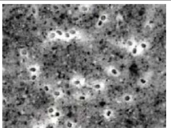
Figure 2.4: A microscopic image showing the white surround of the PVA fibres known as
the Interfacial Transition Zone that provides bond strength between the PVA fibre and
cementitous matrix (Horikoshi et al. 2006)
The ITZ layer formed around the PVA fibre within the cementitious matrix provides
the bond strength between the fibre and matrix.
Noushini et al. (2013) describes the advantages of PVA fibre usage in cementitious
composites to include:
• High aspect ratio (i.e. fibre length to fibre diameter ratio) • High ultimate tensile strength
• Good chemical compatibility with Portland cement • Good affinity with water
• Quicker drainage rate • No risk to health when used
When compared to other organic fibres used in ECCs, PVA fibre exhibits high strength
and modulus of elasticity (Scheffler et al. 2013). Table 2.1 outlines the mechanical
properties of common reinforcing fibres as noted in Section 2.2. As can be noted in
2.2 Fibre Reinforced Concrete 12
Table 2.1: Properties of fibres that are often used in fibre reinforced cementitious
compos-ites (Horikoshi et al. 2006)
Fibre Properties Tensile
Strength (MPa)
Youngs modulus
(GPa)
Fibre elongation
(%)
Specific Gravity
PVA fibre 880–1600 25–40 6–10 1.30
PP fibre 600 5 25 0.91
PE fibre 750–900 3.4–4.9 13–25 1.10
Steel fibre 1200 200 3–4 7.85
Glass fibre 2200 80 0–4 2.78
modulus in the order of 5 times greater than that of PP and PE fibres. For this reason,
PVA fibres inherit better long term crack control performance.
Horikoshi et al. (2006) carried out age acceleration tests on PVA, PE and glass fibre
in an alkaline environment to assess their behaviour during alkaline attack. The fibres
were soaked in hot 80◦C and high alkaline water for 14 days, whereby the PVA fibre
demonstrated a sustained tensile strength compared to PE and glass fibres that showed
a loss in tensile strength. PVA fibre is therefore well suited for the alkaline environment
of the cenemtitious matrix.
2.2.2 Micromechanics
Micromechanics is emphasised as the connecting link between the material
microstruc-ture properties and the composites mechanical performance. As noted in Section 2.2,
micromechanics provides the means of tailoring the fibre, matrix and interface
compo-nents of the composite in order to obtain the optimal performance of an ECC. If the
fibre fraction volume within the composite is too low, strain-softening will be
experi-enced by the composite as per normal FRC. If the fibre fraction volume is too high,
strain-hardening will be experienced by the composite however a waste of fibre
mate-rial and cost will be incurred, in addition to difficulties in matemate-rial processing. It is
therefore important to determine the critical fibre fraction volume at which point the
2.2 Fibre Reinforced Concrete 13 The combination of fibre engineering, fibre and matrix interface and matrix properties
is of utmost importance in order to achieve ductility in ECCs (Wang & Li c. 2005).
The high ductility of ECCs is a result of the interactions between the fibre, matrix
and their interface (Soe et al. 2013). This allows for multi-crack development when
the composite is under tensile load, which in turn allows for strain-hardening to occur.
A simplified explanation is that when the composite is placed under tensile stress,
the first microscopic crack occurs the instant the applied load exceeds the first
crack-load capacity (i.e. cracking strength) of the matrix. The fibres bridging the crack
then share and transfer the load across the crack faces back into the matrix via the
fibre and matrix interface. If the load is capable of being sustained by the fibres and
the interface, then a subsequent parallel crack will occur within the matrix. This
process is repeated and results in a series of sub-parallel microscopic cracks within
the matrix causing the composite to deform and exhibit ductility and strain-hardening
properties (Noushini et al. 2013). In addition, once the composite yield point is reached,
the crack width opening does not increase but instead the number of micro-cracks
increase. Furthermore, when the microscopic cracks begin to form and the fibres begin
to bridge the cracks under load, the bridging stresses within the fibres increase which
in turn increase the shear stresses on the matrix / fibre interface. Failure can then
occur when interface de-bonding is experience (i.e. the fibres pull out of the matrix) or
interface bonding sustains the load however the fibres stretch until rupture (Noushini
et al. 2013). A more detailed and technical explanation of obtaining strain-hardening
shall follow in the subsequent paragraphs.
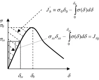
The fibre bridging property that occurs across the matrix crack is referred to as the
tensile stress-separation displacement (σ–δ) curve as shown in Figure 2.5. This
prop-erty is an extremely important component of micromechanics (Li 2003). The bridging
property or the bridging law, describes the relationship between the average tensile
stress (σ) transferred across the matrix crack plane and the separation displacement
(δ) of the crack faces (i.e. Crack Opening Displacement: COD) when subjected to a
uniaxial tensile load. The complementary energy is shown in the hatch area above and
to the left of the curve which shall be discussed in more detail below.
Two governing criterion can be emphasized in order to ensure strain-hardening of ECCs.
These can be referred to as the strength criterion and energy criterion. The strength
bridg-2.2 Fibre Reinforced Concrete 14
Figure 2.5: The σ–δ curve showing the relationship between the average tensile stress (σ)
transferred across the matrix crack plane and the separation displacement (δ) of the crack
faces (Yu & Yang 2011)
ing stress (σ0) of the fibres and thus allows for multiple micro-cracking to occur. If this
criterion is exceeded then a crack will occur from which the load cannot be supported
by the bridging fibres. The energy criterion relates to the style of crack propagation
which in turn is directed by the activity of crack extension. In order to explain crack
propagation we first look at a situation where fibre/matrix interface is weak. In such
situation, fibre pullout will occur when the composite is tensile loaded, resulting in a
σ–δ curve with low peak strength (σ0). If the fibre/matrix interface is too strong then
a spring like interaction (i.e. a slight give and take) does not exist within the composite
which results in stretching of the fibre and then rupture with a small critical opening
δ0. For both such situations, the complementary energy to the left of the σ–δ curve
will be small which in turn results in a crack propagation behaviour whereby failure
of the fibres or fibre/matrix interface begins within the centre of the crack where the
crack opening is maximum (i.e. δm exceeds δ0) and a tension-softening region that
follows the crack tip as the crack propagates. Failure due to a reduced in load carrying
capacity is evident after tension-softening. This type of failure is exhibited for normal
fibre reinforced concrete. However, when the complementary energy is maximised the
crack faces will remain flat during crack propagation in order to maintain a steady state
crack opening (i.e. δss < δ0) whereby the tensile load carrying capacity is sustained,
resulting in the load being transferred back into the matrix and allowing sub-parallel
cracking to occur (Li 2003).
2.2 Fibre Reinforced Concrete 15 the multiple cracking as discussed above but with no increase in crack width (Wang &
Li c. 2005). Micromechanics therefore enhances durability of fibre reinforced concrete
since the maximum allowable crack width should not exceed 80µm in order to ensure the prevention of water penetration.
The fibre, matrix and interface and composite ductility are thus linked by theσ–δcurve. The assurance of multiple cracking is that steady state crack propagation occurs under
tension. This situation prevails when the complementary energy Jb0 is greater than the crack tip toughness Jtip, as determined from the bridging stress versus the crack
opening curve (i.e. σ–δ curve) (Yu & Yang 2011).
Jb0 ≡σ0δ0−
Z δ0
0
σ(δ)dδ (2.1)
Where σ0 is the peak bridging stress andδ0 is the corresponding crack opening.
Jtip =σssδss−
Z δss
0
σ(δ)dδ (2.2)
Whereσssis the bridging stress under which steady state crack openingδssis evident.
For EEC mixes that exhibit a low fibre fraction volume, the crack tip toughness Jtip
approaches the matrix toughness Km2/Em where Km and Em are the fracture
tough-ness and Young’s modulus for the matrix, respectively. It should be noted that these
two variables are sensitive to the mix design criteria, such as water/cement ratio, fine
aggregate size and content. In general a maximum matrix toughness value of 12 N/m
is preferred for ECCs (Wang & Li c. 2005).
The complementary energyJb0and the crack tip toughnessJtipprovide a strain-hardening
indexJb0/Jtip for assessing tensile ductility of the composite. A strain-hardening index
Jb0/Jtip = 1 illustrates that the composite is at the point of is converting from
strain-softening to strain-hardening. An indexJb0/Jtip >1 ensures strain-hardening and leads
to a higher density of multiple cracking.
2.2 Fibre Reinforced Concrete 16 shape of theσ–δ curve is dependent on both the fibre properties and the fibre/matrix interaction parameters. The fibre properties include the fibre volume fraction, diameter,
length, strength and modulus. However it is the fibre/matrix interaction parameters
of interfacial chemical and frictional bond that control the shape of the σ–δ curve (Li 2003). This control is achieved by surface coating the PVA fibre with an oil based
product in order to ensure an excessively high interface bond is not achieved and thus
ensuring rupture failure of the fibre does not occur. However, to high a content of
surface coating results in pullout failure of the fibre from the matrix as discussed above.
The oil content should allow for fibre/matrix interfacial properties in the order of 1.5–
2.5 MPa frictional stress and less than 1.5 N/m interfacial fracture energy (Wang &
Li c. 2005). Li (2003) recommends a surface coating content between 0.8% and 1.2%
by weight of fibres in order to achieve a critical fibre fraction volume of 2% minimum.
Alternatively, fly ash introduced into the matrix is inclined to reduce the interfacial
bond and matrix toughness (Wang & Li c. 2005). Fly ash can serve as an advantage
by improving workability of the mixture and material sustainability however, high fly
ash content reduces early strength grain of the composite. Wang & Li (c. 2005) suggests
a fly ash to cement ratio of 1.2 in order to achieve overall best performance.
Micromechanics therefore provides aσ–δcurve can be further viewed as a link between material design and structural design due to its influence on the stress-strain curve of
the composite. The cost of fibres however outweighs the cost of sand, cement or water
when producing ECCs. The use of micromechanics as a tool to optimise composite
performance with a minimum fibre fraction volume is also useful and important so as
to be able to create an economical composite that is capable of being competitive in
the construction market whilst producing a sustainable product that maintains
strain-hardening properties.
Finally, the water/cement (w/c) ratio of the mixture is a leading variable for controlling
the strength of the composite. A low w/c ratio enhances strength whilst at the same
time helps fibre distribution and maintains mixture consistency. However, a w/c ratio
that is too low can have a negative effect on ECC ductility. For this reason, a w/c of
2.3 PVA Engineered Cementitious Composite Characteristics 17
Table 2.2: Typical mix proportions for PVA engineered cementitious composites
(ECCs) (Wang & Li c. 2005)
Engineered Cementituous Composite Mix Proportions
Fraction Volume % Cement Fine Silica
Sand
Water Superplasticizer (HRWR)
PVA Fibre
1 0.363 0.25 0.02 1.5
Mix Design Proportions
Through the tailoring of micromechanics, mix designs have been created that allow
for an ECC to achieve strain-hardening. Typically, these mix designs will have a low
water/cement ratio and a low cement/aggregate ratio. As noted above in Section 2.2.2,
fly ash may be incorporated into the mix so as to assist with workability however
it does have an effect on fibre/matrix interfacial bond. In addition, superplasticizers
improve workability and may be included with or without fly ash. Furthermore the best
performing fibre fraction volume for a PVA-ECC is between 1.5% - 2.0%. Table 2.2
includes a typical mix proportions for a PVA engineered cementituous composite.
2.3
PVA Engineered Cementitious Composite
Character-istics
An extensive range of research has been undertaken in order to analyse the mechanical
behaviours of ECCs. These studies have been carried out by placing the composite
under quasi-static, cyclic and high rate or impact loading. The characteristics adhered
by ECCs is outlined in Table 2.3 with a discussion below on the mechanical properties
2.3 PVA Engineered Cementitious Composite Characteristics 18
Table 2.3: Typical properties of engineered cementitious composites (ECCs) (Li 2007)
Engineered Cementitious Composite (ECC) Properties Compressive
Strength (MPa)
First Crack Strength
(MPa)
Ultimate Tensile Strength
(MPa)
Ultimate Tensile
Strain (%)
Young’s modulus
(GPa)
Flexural Strength
(MPa)
Density (kg/m3)
20–95 3–7 4–12 1–8 18–34 10–30 950–2300
2.3.1 Compressive Characteristic
Compressive strength is an important characteristic of plain concrete whereby its
im-portance is also transferred to ECC composites. As concrete ages (i.e. cures), it grains
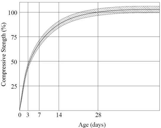
compressive strength. The rate at which concrete gains compressive strength is
indi-cated on Figure 2.6. With reference to Figure 2.6 it can be noted that for concrete
manufactured from general purpose Portland cement, approximately 70% of its
com-pressive strength is gained within the first 7 days and the rate of strength gain is steep.
At the age of 28 days, the concrete has reached its ultimate strength, otherwise known
as its 28-day strength, and the rate of strength gain has begun to plateau. Hence post
28 days, the concrete strength gain is very small and may be considered negligible.
Therefore, concrete strength is determined from its 28 day compressive strength.
Figure 2.6: Typical 28 day strength gain curve of cured concrete (Guide to concrete
2.3 PVA Engineered Cementitious Composite Characteristics 19 PVA-ECC exhibits similar compressive characteristics to that of normal and high
strength concrete. ECCs demonstrate compressive strengths in the range of 20 – 95
MPa and Young’s modulus of approximately 18 – 34 GPa, which it typically lower
than normal concrete and can be associated due to the elimination of coarse aggregate
in ECCs. Regardless of ECCs achieving increased compressive strengths compared to
that of plain concrete, the rate of strength gain still mimics the ageing process of plain
concrete. The successive addition of PVA fibre past the recommended fraction volume
results in a continual reduction in compressive strength for the ECC (Hu et al. 2013).
However, when assessing varying fibre aspect ratios, it can be noted that shorter length
fibre perform better under compressive loads compared to longer length fibres (Noushini
et al. 2013). The compressive strain capacity of ECCs is however in the order of 0.45%
– 0.65% which is marginally higher that plain concrete (Li 2007).
As highlighted previously, the w/c ratio of a mix design affects the compressive strength
of the composite. The higher the w/c ratio for the mixture, the lower the compressive
strength of the concrete. Atahan, Pekmezci & Tuncel (2013) investigated the affects of
two w/c ratios, 0.35 and 0.25, with varying PVA fibre fraction volumes of 0.5%, 1.0%,
1.5% and 2.0% for each. It was noted that an increase of PVA fibre volume with a 0.35
w/c ratio resulted in an increase in compressive strength and a 0.25 w/c ratio resulted
in a higher compressive strength compared to 0.35 w/c ratio. However, in accordance
with Hu et al. (2013) studies, as the fibre fraction volume increased for a mixture with
a w/c ratio of 0.25, the compressive strength decreased. Regardless of such, this paper
will focus on a w/cm ratio of 0.25 since micromechanics recommends this content in
order to satisfy overall performance of ECCs.
It is worth noting that when an ECC is placed under compression, the post-peak
behaviour tends to descend more gradually compared to high strength concrete and
the composite begins to fail via bulging instead of explosive crushing (Li 2007). This
is due to the flexural toughness of an ECC as explained in Section 2.3.4.
2.3.2 Tensile Characteristic
Once a fibre reinforced concrete (FRC) composite has cracked, most of the tensile
forces are transmitted through fibre bridging of the matrix. The tensile behaviour of
2.3 PVA Engineered Cementitious Composite Characteristics 20 Oh 2011). It is therefore expected that the length of fibre used within a composite will
have an effect on the ultimate tensile strength due to fibre/matrix bond. In addition,
the tensile strength increases with curing but only in the initial stages. A rapid tensile
strength gain is witnessed at early age (i.e before 28 days) and then plateaus and does
not increase further (Hu et al. 2013).
High tensile ductility is the most important characteristic of ECCs. This characteristic
is invaluable for improving the structural ultimate limit state (ULS) in the sense of
structural load and deformation capacity in addition to energy absorption (Li 2007).
As noted in Section 2.2.2, the development of multiple microcracking is required in
order to attain strain-hardening and hence high tensile ductility and durability of the
composite. Research has shown that the tensile properties of an ECC material has
been observed to be rate dependent, meaning the rate at which a uniaxial tensile load
is applied to an ECC, has an effect and alters the tensile behaviour and strain capacity
of the composite. It has been shown that the tensile strain capacity decreases with the
increase in strain rate.
Furthermore, composites with higher fibre fraction volume show less reactivity to strain
rate compared with lower fibre fraction volume. Li (2007) states that the ultimate tensile
strength and ultimate tensile strain capacity of an ECC falls between 4–12 MPa and
1–8% respectively.
2.3.3 Flexural Characteristic
The tensile ductility of ECC governs the flexural behaviour of the composite. When
exposed to bending, multiple sub-parallel microcracks form within the tension zone of
the composite thus enabling the existence of larger deflections and curvature by means
of deflection hardening, or otherwise known as strain-hardening. Strain hardening is
a property that is difficult to achieve with standard FRC. As the depth of the FRC
element increases, deflection hardening becomes more difficult to achieve under bending
due to stain-softening. However, the elements geometry does not affect ECCs ability
to attain strain hardening (Li 2007).
A variation in fibre fraction volume does not have a significant effect onflexural strength
2.3 PVA Engineered Cementitious Composite Characteristics 21 does. A higher w/c ratio creates a composite with lower flexural and first cracking
strength (Atahan et al. 2013). This is due to the fact that lower w/cm ratios allow
for improved fibre/matrix interface which in turn resists fibre pullout and enhances
flexural strength. Typically the flexural strength and first crack strength for ECCs
ranges between 10–30 MPa and 3–7 MPa, respectively (Li 2007).
2.3.4 Impact Energy Absorption Characteristic
The high energy absorption characteristic of an ECC is referred to as the materials
flexural toughness whereby it is the composites ability to resist breaking apart. This
property is determined from the calculated area under the load-deflection curve when
exposed to a 4-point bending test (Noushini et al. 2013). An increase in fibre fraction
volume, up to 2%, has shown to have a major impact on the compositesflexural
tough-ness (Atahan et al. 2013). The flexural toughness increases as the fibre fraction volume
increases. Atahan et al. (2013) demonstrated that energy absorption was also affected
by w/c ratio. For a constant PVA fibre fraction volume, a higher w/c results in higher
energy absorbed by the composite. The lower the w/c ratio exhibited by a mixture, the
higher the interfacial bond created between the matrix and the fibres. This results in
fibre rupture which in turn dampens the energy absorption capacity of the composite.
2.3.5 Other Characteristics
Previous studies by Hu et al. (2013) on the mechanical properties of PVA fibre
rein-forced concrete has shown that an increase of water consumption exists within the mix
when there is an increase in fibre volume fraction. This results in a decrease in
work-ability when the concrete is in its plastic state. Hu et al. (2013) also determined that
a decrease in concrete slump corresponded to an increase in fibre content. However, it
is important to note that high workability and high slump do not necessarily always
to go hand in hand. It is possible to have a high slump with low workability or a low
slump with high workability. Workability can be improved by the addition of water
reducing agents, fly ash, an increase in cement content or additional water. However
the addition of water content is not advised as it increases w/c ratio which in turn
re-duces strength and durability and increase the potential for crack propagation (Guide
2.4 Lightweight Engineered Cementitious Composite 22 The addition of PVA fibre to a concrete mix proves to have a small reduction in mass
per unit volume. This reduction is due to the fibre replacing a fraction volume of the
composite mixture whilst having a lighter specific gravity when compared to cement
and sand aggregate. In addition, the fatigue response of ECCs is proven to be greater
than that of normal concrete and FRC. Therefore, ECCs exhibit an extended fatigue
life which is attributed to its high ductility property.
One of the disadvantages of ECCs is that since the engineered mix contains high binder
content (i.e. cement, fine aggregate and fly ash), a very high drying shrinkage is
expe-rienced. When compared to normal structural concrete, the drying shrinkage of ECCs
is about 80% greater (Wang & Li c. 2005). However, regardless of the high drying
shrinkage experienced by ECCs, the composite doesn’t exhibit large shrinkage crack
widths. This is due to the shrinkage being below the tensile strain capacity of the
composite and hence the material is still within stain-hardening stage.
Finally, Young’s modulus of elasticity for an ECC tends to be lower than that of plain
concrete. Reason being is that the modulus of elasticity for PVA fibres is similar to
concrete, but the specific gravity for the fibre is lower, resulting in a maintain volume
where fibres have replaced concrete and therefore reduced the elastic modulus (Hu
et al. 2013).
2.4
Lightweight Engineered Cementitious Composite
In general ECCs have a relatively high density with the maximum being in the order
of 2300 kg/m3. This is similar to that of normal concrete which is about 2400 kg/m3.
The minor reduction in density can be attributed to the replacement of 1.5% – 2.0%
cement volume with a fibre that has a light density. Traditionally, a method of reducing
the density of normal concrete is by including a light-weight aggregate, such as
pyro-processed shales, clays, slate, expanded slags, expanded fly ash or that which has been
extracted from natural porous volcanic sources. In addition, the inclusion of foams into
the mixture results in entrapped air within the concrete that has a further reduction in
density. The densities achieved in normal concrete by these methods ranges between
1400 kg/m3 – 1900 kg/m3.
2.4 Lightweight Engineered Cementitious Composite 23 by altering various aspects of the PVA-ECC mix design with 2% fibre fraction volume.
These methods included air entrapment into the concrete mix and the addition of glass
micro-bubbles, polymeric microform (polymeric micro-hollow bubbles) and expanded
perlite sand as lightweight additives. The research indicated that multiple cracking and
strain-hardening was achieved by all 4 methods; however a PVA-ECC with glass bubble
additive exhibited the better mechanical performances compared to polymeric
micro-hollow bubbles, air entrainment and expanded perlite sand. Ultimately a LWECC
with 2% fibre fraction volume and 20% glass bubble volume fraction replacement was
developed with a density of 1670 kg/m3 and a tensile first crack strength, an ultimate
tensile strength, tensile strain capacity and compressive strength of 3.90 MPa, 4.56
MPa, 3.42% and 43.2 MPa, respectively. A lighter weight PVA-ECC with glass bubbles
with a density of 1450 kg/m3 was developed however this was due to the total removal
of all sand in the mixture whilst maintaining the same glass bubble fraction by weight,
thus resulting in a 38% glass bubble fraction by volume. It can be noted though that
a reduction in tensile first crack strength, ultimate tensile strength and compressive
strength occurred to the value of 29.7%, 5.5%, and 3.0%, respectively, and an increase
in tensile strain capacity of 24.0%. Any glass bubble fraction volume greater than this
results in a composite that is likely unable to achieve strain-hardening. This is due a
reduced interface with the PVA fibre and the cement matrix, as bonding between the
glass bubbles and PVA fibre is limited and a percentage of cement is required in order
for the Interfacial Transition Zone to occur around the PVA fibre.
It can be noted that a general increase in glass bubble fraction volume results in a
gradual reduction in tensile first crack strength and compressive strength however
ul-timate tensile strength and strain capacity are virtually unaffected. Furthermore, the
larger the mean diameter of the glass bubble additive, the greater the reduction in
mechanical properties of the composite. This can be related to the fact that failure of
the composite is first experienced due to the largest flaw in the matrix whereby glass
bubbles may act as such flaws. Air entrainment produces similar behaviour whereby
the increase in entrapped air begins to congregate and produces even larger flaws within
the matrix. Polymeric micro-hollow bubbles don’t perform as well as glass bubbles due
to the even weaker bond to cement and PVA fibre during hydration. When compared
to air entrainment, polymeric micro-hollow bubbles marginally out outperformed this
method. Finally, expanded perlite sand experienced poor strain-hardening due to the
2.4 Lightweight Engineered Cementitious Composite 24 changes in rheology, in addition to the higher porous microstructure of the sand, thus
2.5 Chapter Summary 25
2.5
Chapter Summary
The fundamental property of an ECC is its ability for the composite to achieve
strain-hardening through the process of multi-crack development. Sub-parallel microscopic
cracks occur when the tensile stresses are transferred through the matrix via fibres
bridging the crack faces. Through the development of micromechanics, the cementitious
matrix and the fibre materials have been tailored in order to achieve this property.
Standard FRC designed with low dosage rates of steel fibres, glass fibres and carbon
fibres are not capable of achieving strain-hardening due to the high Young’s modulus
of the fibres when compared to the concrete. Hence ECCs require the use of PVA
fibres, PP fibres or PE fibres that exhibit a low Young’s modulus similar to that of the
cementitious matrix.
In addition to the the high tensile strength of PVA fibres, the phenomena of
hydro-gen bonding occurs within the cementitious matrix surrounding the PVA fibre. The
surrounding area is known as the Interfacial Transition Zone (ITZ) and results in an
extremely strong bond between the PVA fibre and the composite. Hence, a further
requirement in order for PVA-ECC to achieve strain-hardening, is to have the fibre
coated with an oil substance so as to reduce the fibre / matrix interface. Typically, the
mix proportions of an ECC will contain 1.5% – 2.0% fibre fraction volume coated with
an oil substance of 0.8% – 2.0% by fibre weight.
The inclusion of PVA fibres in a cementitious matrix does not significantly change
the compressive strength of the concrete, however it does improve the ultimate tensile
strength and award it the property of ductility. This in turn enhances the energy
absorption capacity of the material.
Lightweight ECCs have been created by incorporating expanded perlite sand, polymeric
microform, glass micro-bubbles and air entrainment as lightweight additives. These
methods have achieved strain-hardening whilst reducing the composite density by up
to 40%. However, a reduction in compressive strength and ultimate tensile strength
Chapter 3
Materials and Mix designs
3.1
Chapter Overview
The following chapter discusses the materials used for the design of the research project
ECC. It highlights the properties and characteristics of the cement, sand, water, PVA
fibre, lightweight hollow glass microspheres and superplasticiser used for the design
of the ECC and how they affect the design. The chapter further defines the mix
design proportions and mix design quantities adopted for the ECC design and how
each material quantity for each mix design was determined.
3.2
Materials
Typical concrete is a mixture of cement, aggregate and water. Concrete can also include
admixtures such as fly-ash, slag, water reducing agents (i.e. superplasticisers), retarders
and accelerators. A composite incorporates other materials whose main function is to
act as reinforcement. The materials used to create concrete in this research are cement,
fine sand aggregate, water and superplasticiser. The additional cementitous composite
materials include PVA fibre and hollow glass mircospheres. Each of these materials are
3.2 Materials 27
(a) Front of bag (b) Back of bag
Figure 3.1: Cemix GP cement bags that were used for preparing the mix design samples
3.2.1 Cement
Cement is the binding agent of a concrete mixture and may be produced as an inorganic
or a organic material. General cement is further divided into Portland cement and
Blended Cement. General Purpose Portland (GP) cement has been adopted for this
research. It is an inorganic cement that consists of a mixture of finely ground calcium
carbonate, alumina, silica, and iron oxide. These materials are kiln dried at high
temperatures of 1300 to 1500◦C whereby they are partially fused to form clinker (i.e.
a ceramic-like material that takes the form of small hard balls) (Guide to concrete
construction2002). In addition, the chemical compound of the clinker is altered during
the kiln process whereby the material becomes reactive to water. Once removed from
the kiln, the clinker is cooled and mixed with gypsum (calcium sulfate) and again
ground to a fine powder that is commonly know as cement. Gypsum is required in
order to govern the rate at which the cement hydrates when mixed with water (Guide
to concrete construction 2002).
The cement used in this research was Cemix GP cement purchased from a common
3.2 Materials 28
Figure 3.2: A mix design portion of Cemix GP cement in its fine ground powder form as
viewed from above
Figure 3.2 displays the Cemix GP cement in its ground powder form. It can be noted
that the grey colour of this cement is primarily due to the presence of iron infused into
the clinker.
3.2.2 Fine Sand Aggregate
Natural sand aggregates are typically sourced from stream beds, dunes and alluvial
deposits. Australian Standard AS2758.1 requires that the grading of sand ranges
be-tween 75µm and 9.50 mm when used for concrete. This research adopted natural sand aggregates sourced from alluvial river beds that was then further separated by means of
sieving to fine sand aggregates with a grading between 75 to 250µm and 250 to 425µm as discussed in Section 4.3. Figure 3.3 shows the sand aggregate that was purchased
for the research project.
3.2 Materials 29 It can be noted that a concrete mix design with a high content of fines will have a higher
water demand and reduced workability. Hence one of the reasons for the inclusion of
superplasticisers in ECC mix designs, in order to improve the workability as discussed
in Section 3.2.6.
3.2.3 Water
In general, the water used to produce concrete is to be either potable water (i.e. suitable
as drinking water) or water that is free from impurities. Impurities in the water may
be suspended solids, organic matter or salts, however there is a minimal allowance of
such contaminents whereby water would still be considered as suitable. Typically, a
maximum of 2% of fine silt and/or clay suspended solids smaller than 2 mm is allowed
in the water. High organic matter in the water will impact the concrete strength
and could preve