i
“I confess that, this report is my own revenue except the synopsis and quotation that every part I did explain the sources”
Signature : ………..
Writer’s name : Adam Maleck Bin Hamid
ii
ACKNOWLEDGEMENT
“In The Name of Allah, The Merciful, The Beneficent”
Glory to Allah S.W.T the most gracious; the most merciful and peach is upon his messenger Holy Prophet Muhammad S.A.W. All the worship belongs to only Allah. We seek refuge with Allah from the wickedness within and from the evil deeds. We also praised to Allah S.W.T. for giving us courage, time, and knowledge in completing this report for bachelor project 1.
Alhamdulillah, at last this report is ready on the day it is due finish. Whilst accepting full responsibility for the contents of this work, it would churlish not to acknowledge the debt ourselves to all those who, directly or indirectly contributed to this writing. It has a most fruitful experience to have been able to do this report.
iii
ABSTRACT
iv
ABSTRAK
v
TABLE OF CONTENT
CONTENT Page
CONFESSION i
ACKNOWLEDGEMENT ii
ABSTRACT iii
ABSTRAK iv
TABLE OF CONTENT v
LIST OF TABLES viii
LIST OF GRAPH ix
LIST OF FIGURES x
NOMENCLATURE xiii
LIST OF APPENDICES xiv
CHAPTER 1 INTRODUCTION
1.1 Background 1
1.2 Problem Statement 2
1.3 Objective of project 2
1.4 Scopes of project 2
1.5 Project planning 3
1.6 Summary 4
CHAPTER 2 LITERATURE REVIEW
2.1 Introduction 5
2.2 DFA & DFM Methodologies 5
2.3 How does DFMA works 12
vi
2.5 Boothroyd Dewhurst Method 18
2.6 Lucas Method 25
2.7 AEM Method 30
2.8 Manual Method 35
2.9 Automatic Method 36
2.10 Robotic Method 37
2.11 Summary 39
CHAPTER 3 METHODOLOGY
3.1 Introduction 40
3.2 EFA Methodology 40
3.3 Compliant Mechanism 54
3.4 Case study on simple compliant product 66
3.5 Application of the EFA Methodology 68
3.6 Compliant Product Survey 70
3.7 Summary 73
CHAPTER 4 PRODUCT CASE STUDY
4.1 Introduction 74
4.2 Product Selection 74
4.3 Re-Design product using EFA Method 75
4.4 Summary 78
CHAPTER 5 DESIGN CONCEPT
5.1 Introduction 79
5.2 Conceptual Design 79
5.3 Ideation Sketch & Concept Generation 80
5.4 Concept Selection 82
5.5 Detail Design using CAD 83
vii
5.7 Fabricate Mock-up Using Rapid Prototyping 87
5.8 Summary 90
CHAPTER 6 RESULT AND ANALYSIS
6.1 Introduction 91
6.2 Cosmoswork Analysis Result 91 6.3 Re-Design Material Properties 94 6.4 Summary 98 CHAPTER 7 DISCUSSION 7.1 Introduction 99
7.2 Testing and Analyze the Mock-up 99
7.3 Improvement in Design 100
7.4 Summary 102
CHAPTER 8 CONCLUSION AND RECOMMENDATION 8.1 Conclusion 103
8.2 Recommendation 105
REFERENCE 106
APPENDIX A 108
viii
LIST OF TABLES
NO TITLE PAGE
2.1 Boothroyd Dewhurst worksheet 20
2.2 Manual assembly worksheet for the original design 22
2.3 Manual assembly worksheet for Redesign 1 23
2.4 Manual assembly worksheet for Redesign 2 24
2.5 Lucas methods - Manual Handling Analysis (Appendix B) 111 2.6 Lucas method - Manual Fitting Analysis (Appendix B) 112 2.7 Evaluation score and the cost ratio of the original design 32 2.8 Evaluation score and the cost ratio of redesign 1 33 2.9 Evaluation score and the cost ratio of redesign 2 34
2.10 Commercially available DFA methods 39
3.1 Relative Motions 41
4.1 Bill of Material for bolt clipper cutter with tubular handle 75
6.1 Cast Carbon Steel Properties 95
6.2 Acrylonitrile butadiene styrene (ABS) Properties 95
6.3 Material Description 96
6.4 Re-design Analysis Result 97
ix
LIST OF GRAPH
NO TITLE PAGE
x
LIST OF FIGURES
NO TITLE PAGE
1.1 Flow Chart for bachelor project 3
1.2 Gantt chart for Bachelor Project (Appendix A) 108
2.1 Example of simplify parts. 12
2.2 Shows if screws must be used, try integrating washers with the
screw heads; this will eliminate at least one part. 16 2.3 Show how part reduction replaces separate springs with parts
with thin sections that act as springs. 17
2.4 Show how DFA improving handle ability of a part by redesign 17
2.5 Example DFA solution for symmetry part 17
2.6 Flow diagram of the Boothroyd-Dewhurst method 21 2.7 “Original design” before re-design using Boothroyd Dewhurst
Method 22
2.8 Redesign 1, from “Original design” 23
2.9 Redesign 2 from “Redesign 1” 24
2.10 Original drain pump assembly design (Appendix A) 109 2.11 Redesign using the Lucas method (Appendix A) 110
2.12 AEM Method procedures 31
2.13 “Original design” before redesign using AEM method 31
2.14 Redesign 1 using AEM method 32
2.15 Redesign 2 from “redesign 1” 33
2.16 Relative costs of different assembly methods by type and
production volume. 37
2.17 Production ranges for each type of assembly method 38
xi
3.2 External Links 46
3.3 First Order Analysis 48
3.4 Second Order Analysis 50
3.5 Nth Order Analyses 51
3.6 Necessary Conditions for EFA Method 52
3.7 Overall EFA process 53
3.8 Vice grips “compliant mechanism” 55
3.9 example of a compliant crimping mechanism 55
3.10 Compliant Mechanisms and its Pseudo-Rigid-Body Model 56 3.11 Compliant mechanisms and their rigid-body equivalents 59
3.12 Classification Compliant Mechanisms 62
3.13 Various flexible segments and their pseudo-rigid-body models 63
3.14 Flexible segment and Pseudo-Rigid Body model 64
3.15 Compliant slider mechanism and Pseudo Rigid Body model 65
3.16 Exploded parts for Stapler 67
3.17 Single piece compliant Stapler 67
3.18 Nail Cutter and kinematics diagram 68
3.19 Type of link for nail cutter 69
3.20 Compliant nail cutter designs 69
3.21 Compliant wiper 70
3.22 Compliant overrunning clutch 71
3.23 Compliant Umbrella (re-design) 72
4.1 Bolt Clipper Cutter with Tubular Handle 74
4.2 Position of Bolt Cutter Clipper with Tubular Handle 75 4.3 Kinematics diagram for Bolt clipper cutter with tubular handle 76
4.4 Kinematics diagram after eliminating parts 77
5.1 Conceptual Design 1 80
xii
5.3 Conceptual design 3 81
5.4 Selection conceptual design 82
5.5 Compliant Handle for Bolt Clipper 83
5.6 Cutter for bolt clipper 84
5.7 Cutter supporter 84
5.8 Rivets for Bolt Clipper Cutter 85
5.9 Final design 86
5.10 Dimension for re-design bolt clipper cutter 86
5.11 Rapid Prototyping Machine 87
5.12 Apparatus for soak the mock-up 88
5.13 Finished mock-up using rapid prototyping 89
6.1 Stress Analysis for compliant part 92
6.2 Displacement Analysis for compliant part 93
6.3 Strain Analysis for compliant part 94
xiii
NOMENCLATURE
DFA : Design for Assembly DFM : Design for Manufacture
DFMA : Design for Manufacture and Assembly EFA : Effort Flow Analysis
DNA : Design for No-Assembly DFX : Design for Excellence DOF : Degree of Freedom ASF : Assembly Flow Flowchart ABS : Acrylonitrile Butadiene Styrene RP : Rapid Prototyping
PDM : Product Data Management
xiv
LIST OF APPENDICES
NO TITLE APPENDIX
1.2 Gantt chart for Bachelor Project A
2.10 Original drain pump assembly design A
2.11 Redesign using the Lucas method A
2.5 Lucas methods - Manual Handling Analysis B
1
CHAPTER 1
INTRODUCTION
1.1 Background
The aim of design for assembly (DFA) is to simplify the product so that the
cost of assembly is reduced. However, consequences of applying DFA usually
include improved quality and reliability, and a reduction in production equipment
and part inventory. These secondary benefits often outweigh the cost reductions in
assembly.
DFA recognizes the need to analyze both the part design and the whole
product for any assembly problems early in the design process. DFA defines as a
process for improving product design for easy and low-cost assembly, focusing on
functionality and on assemblability concurrently [1]."
The practice of DFA as a distinct feature of designing is a relatively recent
development, but many companies have been essentially doing DFA for a long time.
For example, General Electric published an internal manufacturing producibility
handbook in the 1960's as a set of guidelines and manufacturing data for designers to
follow. These guidelines embedded many of the principles of DFA without ever
actually calling it that or distinguishing it from the rest of the product development
2
1.2 Problem Statement
Design for assembly now is an important thing in production to reduced
assembly operation, reduced product lead time, reduced overall system and product
cost. Many methods are introduced an approach for minimize the number of part and
ease to assembly. This report will analyze the use of Effort Flow Analysis (EFA)
method for part count reduction and how EFA method make solution in design that
having varying degrees and relative motion became a compliant product.
1.3 Objective of project
The main objective is to study, analyze and identify the use of EFA method
for part count reduction through part combination that having varying degrees of
relative motion.
1.4 Scopes of project
The scopes of project as listed below.
1. To study the other DFA Methodologies
2. To study the EFA Method
3. To present compliant product case study on how the application of EFA
4. To generate conceptual design and detail design using CAD software
3
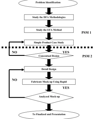
1.5 Project planning
The project divided into two part; bachelor project 1 and bachelor project 2,
because need to running the project in two semesters. Bachelor project 1 is about
study the problem statement, study the methodology design for assembly, specific
method studies on EFA, and study on compliant mechanism.
Bachelor project 2 more on re-design the product selected with using EFA
method, detail conceptual design, modelling by using CAD software and fabricate a
mock-up using rapid prototyping machine. Figure 1.1 shows the flow of project
[image:17.612.170.476.291.683.2]planning for both bachelor projects. Gantt chart for this project shown at appendix (A)
Figure 1.2.
PSM 1
NO YES
PSM 2
NO
YES
Figure 1.1 Flow Chart for bachelor project. Problem Identification
Study the DFA Methodologies
Study the EFA Method
Fabricate Mock-up Using Rapid Prototyping Detail Design Conceptual Design Simple Product Case Study
Analyzed Mock-up
4
1.6 Summary
In chapter 1, describe the problem statement, objective, scope and planning
for overall bachelor project. Project duration is two semesters for complete the
project. Start from study the DFA methods, specific study on EFA methods, and to
study the simple compliant mechanism and product. Actually EFA method is related
with compliant mechanism. In semester two, bachelor project will continue with
re-design the selected existing product using EFA method, re-designing process involve
the conceptual design, detail design using Computer Aided Design (CAD) software
5
CHAPTER 2
LITERATURE REVIEW
2.1 Introduction
Design for Assembly is a process by which products are designed with ease
of assembly. If a product contains fewer parts it will take less time to assemble and at
the same time reducing the assembly cost. In addition, if parts are provided with
features which make it easier to handle, to move, insertion, to grasp, orient, not too
small and sharp. All of this will reduced assembly time and cost.
2.2 DFA & DFM Methodologies
Design For Assembly (DFA) and Design For Manufacture (DFM) actually
related each other. Combination DFA and DFM called as Design For Manufacture
and Assembly (DFMA). This method developed in 1980 by Geoffrey Boothroyd and
Peter Dewhurst, professors of industrial and manufacturing engineering at the
University of Rhode Island in kingston. Starting in 1981, Geoffrey Boothroyd and
Peter Dewhurst developed a computerised version of DFA method which allowed its
implementation in a broad range of companies. DFA methods is a simply approach
to designing products with easy manufacture and also makes the assembly process
6
Basic guidelines for DFA, generally start with a concept design and then go
through each of these guidelines, decide whether or not it is applicable, and improve
the concept to satisfy the guideline. There is no guarantee that a given guideline will
apply to a particular design problem. Many of these guidelines are similar or the
same as rules of concurrent engineering;
• Minimise part count by using multiple functions into single parts
• Modularise multiple parts into single subassemblies
• Assemble in open and large space, not in confined spaces; never bury
important components
• Make parts such easy to identify and show easy oriented for insertion
• Prefer self-locating parts
• Standardise to reduce part variety
• Maximise part symmetry
• Design in geometric or weight polar properties if no symmetric
• Eliminate tangle parts
• Colour code parts that are different but shaped similarly
• Prevent nesting of parts; prefer stacked assemblies
• Provide orienting features on no symmetries
• Design the mating features for easy insertion
• Provide alignment features
• Insert new parts into an assembly from above
• Eliminate re-orientation of both parts and assemblies
• Eliminate fasteners
• Place fasteners away from obstructions; design in fastener access
• Deep channels should be sufficiently wide to provide access to fastening tools;
eliminate channels if possible
• Provide flats for uniform fastening and fastening ease
Basic guideline DFM as below
1. Simplify the design and reduce the number of parts because for each part, there is
an opportunity for a defective part and an assembly error. The probability of a perfect
product goes down exponentially as the number of parts increases. As the number of
7
Automation becomes more difficult and more expensive when more parts are
handled and processed. Costs related to purchasing, stocking, and servicing also go
down as the number of parts are reduced. Inventory and work-in-process levels will
go down with fewer parts. As the product structure and required operations are
simplified, fewer fabrication and assembly steps are required, manufacturing
processes can be integrated and lead-times further reduced. The designer should go
through the assembly part by part and evaluate whether the part can be eliminated,
combined with another part, or the function can be performed in another way. To
determine the theoretical minimum number of parts, ask the following: Does the part
move relative to all other moving parts? Must the part absolutely be of a different
material from the other parts? Must the part be different to allow possible
disassembly? [6].
2. Standardize and use common parts and materials to facilitate design activities, to
minimize the amount of inventory in the system, and to standardize handling and
assembly operations. Common parts will result in lower inventories, reduced costs
and higher quality. Operator learning is simplified and there is a greater opportunity
for automation as the result of higher production volumes and operation
standardization. Limit exotic or unique components because suppliers are less likely
to compete on quality or cost for these components. The classification and retrieval
capabilities of product data management (PDM) systems and component supplier
management (CSM) systems can be utilized by designers to facilitate retrieval of
similar designs and material catalogs or approved parts lists can serve as references
forAcommonApurchasedAandAstockApartsA[6].
3. Design for ease of fabrication. Select processes compatible with the materials and
production volumes. Select materials compatible with production processes and that
minimize processing time while meeting functional requirements. Avoid unnecessary
part features because they involve extra processing effort and/or more complex
tooling. Apply specific guidelines appropriate for the fabrication process such as the
following guidelines for machine ability [6]:
8
• Use near net shapes for moulded and forged parts to minimize machining and
processing effort.
• Design for ease of fix Turing by providing large solid mounting surface &
parallel clamping surfaces
• Avoid designs requiring sharp corners or points in cutting tools - they break
easier
• Avoid thin walls, thin webs, deep pockets or deep holes to withstand
clamping & machining without distortion
• Avoid tapers & contours as much as possible in favour of rectangular shapes
• Avoid undercuts which require special operations & tools
• Avoid hardened or difficult machined materials unless essential to
requirements
• Put machined surfaces on same plane or with same diameter to minimize
number of operations
• Design work pieces to use standard cutters, drill bit sizes or other tools
• Avoid small holes (drill bit breakage greater) & length to diameter ratio > 3
(chip clearance & straightness deviation)
4. Design within process capabilities and avoid unneeded surface finish
requirements. Know the production process capabilities of equipment and establish
controlled processes. Avoid unnecessarily tight tolerances that are beyond the natural
capability of the manufacturing processes. Otherwise, this will require that parts be
inspected or screened for acceptability. Determine when new production process
capabilities are needed early to allow sufficient time to determine optimal process
parameters and establish a controlled process. Also, avoid tight tolerances on
multiple, connected parts. Tolerances on connected parts will "stack-up" making
maintenance of overall product tolerance difficult. Design in the center of a
component's parameter range to improve reliability and limit the range of variance
around the parameter objective. Surface finish requirements likewise may be
established based on standard practices and may be applied to interior surfaces
9
5. Design for parts orientation and handling to minimize non-value-added manual
effort and ambiguity in orienting and merging parts. Basic principles to facilitate
parts handling and orienting are [6]:
• Parts must be designed to consistently orient themselves when fed into a
process.
• Product design must avoid parts which can become tangled, wedged or
disoriented. Avoid holes and tabs and designed "closed" parts. This type of
design will allow the use of automation in parts handling and assembly such
as vibratory bowls, tubes, magazines, etc.
• Part design should incorporate symmetry around both axes of insertion
wherever possible. Where parts cannot be symmetrical, the asymmetry should
be emphasized to assure correct insertion or easily identifiable feature should
be provided.
• With hidden features that require a particular orientation, provide an external
feature or guide surface to correctly orient the part.
• Guide surfaces should be provided to facilitate insertion.
• Parts should be designed with surfaces so that they can be easily grasped,
placed and fixture. Ideally this means flat, parallel surfaces that would allow
a part to picked-up by a person or a gripper with a pick and place robot and
then easily fixture.
• Minimize thin, flat parts that are more difficult to pick up. Avoid very small
parts that are difficult to up or require a tool such as a tweezers to
pick-up. This will increase handling and orientation time.
• Avoid parts with sharp edges, burrs or points. These parts can injure workers
or customers, they require more careful handling, they can damage product
finishes, and they may be more susceptible to damage themselves if the sharp
edge is an intended feature.
• Avoid parts that can be easily damaged or broken.
• Avoid parts that are sticky or slippery (thin oily plates, oily parts, adhesive
backed parts, small plastic parts with smooth surfaces, etc.).
• Avoid heavy parts that will increase worker fatigue, increase risk of worker
10
• Design the work station area to minimize the distance to access and move a
part.
• When purchasing components, consider acquiring materials already oriented
in magazines, bands, tape, or strips.
6. Minimize flexible parts and interconnections. Avoid flexible and flimsy parts such
as belts, gaskets, tubing, cables and wire harnesses. Their flexibility makes material
handling and assembly more difficult and these parts are more susceptible to damage.
Use plug-in boards and backplanes to minimize wire harnesses. Where harnesses are
used, consider fool proofing electrical connectors by using unique connectors to
avoid connectors being misconnected. Interconnections such as wire harnesses,
hydraulic lines, piping, etc. are expensive to fabricate, assemble and service.
Partition the product to minimize interconnections between modules and co-locate
related modules to minimize routing of inter connections [6].
7. Design for ease of assembly by utilizing simple patterns of movement and
minimizing the axes of assembly. Complex orientation and assembly movements in
various directions should be avoided. Part features should be provided such as
chamfers and tapers. The product's design should enable assembly to begin with a
base component with a large relative mass and a low center of gravity upon which
other parts are added. Assembly should proceed vertically with other parts added on
top and positioned with the aid of gravity. This will minimize the need to re-orient
the assembly and reduce the need for temporary fastening and more complex fix
Turing. A product that is easy to assemble manually will be easily assembled with
automation. Assembly that is automated will be more uniform, more reliable, and of
a higher quality [6].
8. Design for efficient joining and fastening. Threaded fasteners (screws, bolts, nuts
and washers) are time-consuming to assemble and difficult to automate. Where they
must be used, standardize to minimize variety and use fasteners such as self
threading screws and captured washers. Consider the use of integral attachment
methods (snap-fit). Evaluate other bonding techniques with adhesives. Match