Multi-link laser interferometer architecture
for a next generation GRACE
Samuel Peter Francis
A thesis submitted for the degree of Doctor of Philosophy
at the Australian National University
Submitted 31st May, 2017
c
Declaration
This thesis is an account of research undertaken between February 2013 and May 2017 at The Centre for Gravitational Physics, Department of Quantum Science, The Australian National University, Canberra, Australia.
Except where acknowledged in the customary manner, the material presented in this thesis is, to the best of my knowledge, original and has not been submitted in whole or part for a degree in any university.
Acknowledgements
This research is supported by an Australian Government Research Training Program (RTP) Scholarship. The research described in this thesis was also supported under the Australian Research Council’s Discovery Projects funding scheme (project number DP140103575). The research was also completed as a recipient of a student scholarship from the Space Environment Research Centre (SERC).
A PhD is a colossal task, something I didn’t appreciate fully when I first started. I have made it to the end but this was not without the support and guidance of others.
To my primary supervisor Daniel, I am incredibly grateful for your time and encourage-ment throughout the years. I have the highest respect for you and am inspired by your ability to explain even the most complicated concepts in a way that is easy to understand. Sorry that you won’t be able to introduce me as a final year PhD student again.
Tim, thanks for all of your help and your patience and understanding. You are a hard taskmaster but that is exactly what I needed to motivate me to get my thesis finished.
David, thanks for making the Centre for Gravitational Physics what it is. The centre has been an amazing place to complete my thesis with a work culture unlike anything I have experienced before. I hope that wherever I go next can be as fun and rewarding.
I’ve been in the Centre for Gravitational Physics since 2011. Over this time I have been lucky to work with lots of exceptionally smart people. Lyle, you introduced me to the group and have been a mentor since my days as an undergraduate. Thanks. Special thanks also to Georgia, Shasi, Thanh and Silvie for their friendship over the years. It’s nice to have friends at work but even better when they are among your best friends. Thanks to all of the the other graviteers. The postdocs – Robert Ward, Bram Slagmolen, Jong Chow, Paul Altin, Roland Fledderman, and Terry McRae – even if I didn’t work with you directly, you provided support and advice when needed. Graviteers of the past – Danielle, Andrew Sutton, Andrew Wade, Sheon, Alberto, Conor – you taught me the tricks of the trade and proved that there was light at the end of the tunnel. And graviteers of the present – Jarrod, Min Jet, Chatters, Paul Sibley, David McManus, Tarquin, Perry, Nathan, Cathy, Keshu – thanks for all of the fun times.
I have had some incredible opportunities during my PhD. Thanks Kirk, Brent, Bob and Bill at the Jet Propulsion Laboratory for hosting my visit and your continued support when I email you questions about GRACE. Thanks Harry, Christian, Mike, David and everyone else at the Institute for Gravitational Research who made my stay in Glasgow so enjoyable. Thanks to Simon Gross from OptoFab at Macquarie University for building the 3D laser written waveguide. And thanks to everyone in Liquid Instruments. It has been a hugely rewarding experience being part of this small (but growing) team and I look forward to seeing where it will go.
Thanks to my family for their love and support and thanks for making me into the person I am today. Without you, none of this would have been possible.
Abstract
When GRACE Follow-On (GRACE-FO) launches, it will be the first time a laser in-terferometer has been used to measure displacement between spacecraft. In the future, interspacecraft laser interferometry will be used in LISA, a space-based gravitational wave detector, that requires the change in separation between three spacecraft to be measured with a resolution of 1 pm/√Hz. The sensitivity of an interspacecraft interferometer is potentially limited by spacecraft degrees-of-freedom, such as rotation, coupling into the interspacecraft displacement measurement. GRACE-FO and LISA therefore have strict requirements placed on the positioning and alignment of the interferometers during space-craft integration.
Decades of work has gone into adapting traditionally lab-based techniques for these space applications. As an example, GRACE-FO stops rotation of the two spacecraft from coup-ling into displacement using the triple mirror assembly. The triple mirror assembly is a precision optic, comprised of three mirrors, that function as a retroreflector. Provided the triple mirror assembly vertex coincides with the spacecraft centre of mass, any spacecraft rotation will asymmetrically lengthen and shorten the optical pathlengths of the incoming and outgoing beams, ensuring that the round trip pathlength between the spacecraft is unaffected. To achieve the required displacement sensitivity, the triple mirror assembly vertex must be positioned within 0.5 mm of the spacecraft centre of mass, making space-craft integration challenging.
In this thesis a new, all-fibre interferometer architecture is presented that aims to simplify the positioning and alignment of space-based interferometers. Using multiple interspace-craft link measurements and high-speed signal processing the interspaceinterspace-craft displacement is synthesised in post-processing. The multi-link interferometry concept is similar to the triple mirror assembly’s symmetric suppression of rotation, however, since the rotation-to-pathlength cancellation is performed in post-processing, the weighting of each inter-spacecraft link measurement can be optimised to completely cancel any rotation coupled error. Consequently, any uncertainty in the positioning of the multi-link interferometer during spacecraft integration can be corrected for in post-processing. The strict hardware integration requirements of current interferometers can therefore be relaxed, enabling a new class of simpler, cheaper missions.
The multi-link concept is evaluated as a potential interferometer architecture for a next generation GRACE mission. The multi-link GRACE concept uses several fibre coupled optical heads on each spacecraft to form multiple interspacecraft links between spacecraft. To cancel rotation coupled error from rotation of both spacecraft, 9 interspacecraft links are formed between 3 optical heads positioned on each spacecraft. Displacement is meas-ured in both directions along each link using digitally implemented phasemeters. The 18 interspacecraft displacement measurements are then combined using artificial delays and different weights to cancel laser frequency equivalent displacement noise, fibre pathlength fluctuations and rotation coupled displacement error.
interspacecraft links, the beam divergence out of each optical head is made sufficiently large so that links can be acquired without requiring a dedicated link acquisition strategy. Although this design simplifies the spacecraft integration and alignment it comes with some challenges: without an active link acquisition, the received power on the distant spacecraft could be considerably lower than in GRACE-FO; time delay interferometry has not been tested on a GRACE-like interferometer; and the cancellation of rotation-to-pathlength coupled error using a weighted average of multiple link measurements has not been demonstrated. Three experiments are presented in this thesis, addressing these challenges.
In both GRACE-FO and LISA, phasemeters are used to track the phase of the lasers transmitted along each interspacecraft link. Tracking the phase of optical signals with low signal-to-noise ratios (SNR) is difficult because the higher, relative noise can lead to nonlinear behaviour in the phasemeter. In the first experiment presented in this thesis, the dominant noise sources – laser frequency noise and shot noise – that limit the phasemeter’s ability to track low SNR signals are analysed. By optimising the phasemeter bandwidth to minimise the error from these two noise sources, the probability of nonlinear phasemeter behaviour is also minimised. A benchtop demonstration was performed to verify the analysis, with the bandwidth optimisation used to track a 30 fW freerunning signal -the lowest power signal that has been tracked to date. The analysis indicates that sub-femtowatt signals could be tracked if the laser frequency is pre-stabilised.
The second experiment describes the development of a time delay interferometry combin-ation for a GRACE-like interferometer that recovers the displacement sensitivity of the phase locked GRACE-FO interferometer. The combination could be used to test time delay interferometry on GRACE-FO as part of the LISA Experience On Grace Optical Payload (LEGOP) project. It also demonstrates time delay interferometry could be used on a GRACE-like interferometer for laser frequency displacement noise suppression. The proposed test uses a tone assisted time delay interferometric ranging (TDIR) algorithm to determine the delays required to suppress the displacement noise due to one laser in the displacement measurement between the GRACE spacecraft. Under simulated GRACE-FO conditions, the tone assisted TDIR algorithm was used to suppress the laser frequency equivalent displacement noise by 8 orders of magnitude. This was below the residual laser frequency displacement noise requirement on GRACE-FO of 20 nm/√Hz. An ex-perimental test of the algorithm demonstrated the capabilities of the proposed algorithm in the presence of large path length fluctuations, a macroscopic optical delay and different electronic delays.
The third experiment tested the multi-link GRACE architecture. In the benchtop ex-periment a local spacecraft with 3 optical heads was modeled. Pitch and yaw of the local spacecraft were emulated using the tip and tilt actuators on a piezo-electric steering mirror. The displacement was measured along 3 links formed between the local optical heads and a single distant spacecraft optical head. Using a weighted average of the 3 link measurements, rotation-to-pathlength coupled error from the simulated pitch and yaw of the local spacecraft were suppressed by up to 18 dB. In addition to spacecraft rotation, tones were injected to model laser frequency noise, fibre fluctuations and an ‘interspace-craft’ displacement signal. The laser noise, fibre noise and rotation-to-pathlength noise were all suppressed down to the 1 nm/√Hz measurement noise floor without affecting the measurement of the ‘interspacecraft’ displacement signal.
Contents
Declaration iii
Acknowledgements v
Abstract vi
List of Figures xvii
List of Tables xix
1 Candidate laser interferometer architecture for next generation GRACE 1
1.1 Rotation-to-pathlength coupling in an interspacecraft laser interferometer . 2
1.2 A new laser interferometer architecture for a next generation GRACE . . . 4
1.3 Thesis outline . . . 6
1.4 Publications . . . 8
2 Current laser interferometer architectures for interspacecraft metrology 9 2.1 LISA and the GRACE-FO laser ranging interferometer . . . 9
2.2 Measuring interspacecraft displacement . . . 10
2.2.1 Heterodyne displacement interferometry . . . 11
2.2.2 Phasemeter displacement measurements . . . 12
2.3 Limiting noise in an interspacecraft displacement measurement . . . 14
2.3.1 Spurious reflections, cyclic error and digitally enhanced heterodyne interferometry . . . 14
2.3.2 Laser frequency noise . . . 18
2.3.3 Quantum noise . . . 21
2.3.4 Rotation-to-pathlength coupling and link misalignment errors . . . . 24
2.4 Chapter summary . . . 25
3 Multi-link GRACE 27 3.1 Multi-link interferometry concept . . . 27
3.2 Similarities with existing techniques . . . 29
Contents
3.2.2 Triple mirror assembly . . . 31
3.2.3 Post-processing corrections using attitude measurements in GRACE 32 3.3 Implementing a multi-link interferometer . . . 33
3.3.1 Multi-link interferometry requirements . . . 33
3.3.2 An example multi-link interferometer implementation . . . 34
3.3.3 Measuring displacement along each link . . . 35
3.3.4 Suppressing unwanted heterodyne signals on the detector . . . 36
3.4 Synthesising the line-of-sight displacement . . . 38
3.4.1 Overview of signal processing . . . 38
3.4.2 One-way displacement measurements . . . 38
3.4.3 Summary of one-way displacement measurements . . . 40
3.4.4 Cancelling laser frequency and pathlength noise . . . 41
3.4.5 Summary of round-trip displacement measurements . . . 42
3.4.6 Suppressing rotation-to-pathlength coupling with a weighted average 43 3.4.7 Line-of-sight displacement . . . 44
3.5 Uncertainties in a multi-link interferometer . . . 44
3.5.1 Sensitivity to the roll, pitch and yaw of the spacecraft . . . 45
3.5.2 Weighted averages with 3 or more optical heads . . . 46
3.5.3 Positioning and stability of optical heads . . . 47
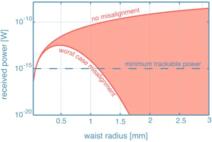
3.5.4 Signal-to-noise ratio of the recovered line-of-sight displacement . . . 48
3.5.5 Acquiring the links between multiple optical heads . . . 51
3.6 Challenges of the multi-link architecture . . . 53
3.7 Chapter summary . . . 54
4 Low SNR phase tracking 55 4.1 Tracking the phase of signals with low SNR . . . 56
4.1.1 Cycle slipping in a phase locked loop . . . 56
4.1.2 Previous work on tracking low SNR optical signals . . . 57
4.2 Modelling cycle slips in a phasemeter . . . 58
4.2.1 Nonlinear phasemeter behaviour . . . 58
4.2.2 Predicting cycle slips . . . 59
4.3 Bandwidth optimisation to minimise cycle slipping . . . 61
4.3.1 Phasemeter bandwidth . . . 62
4.3.2 Optimal bandwidth . . . 63
Contents
4.4.2 Low SNR phase tracking results . . . 68
4.5 Chapter summary . . . 71
5 Post-processing suppression of laser frequency displacement noise in GRACE 73 5.1 LISA Experience of GRACE Optical Payload . . . 74
5.2 Time Delay Interferometry in LISA . . . 74
5.2.1 Delaying measurements in post-processing . . . 74
5.2.2 Laser frequency displacement noise suppression in LISA . . . 75
5.2.3 Determining the interspacecraft delay . . . 76
5.3 Time delay interferometry on GRACE-FO . . . 77
5.3.1 Substituting phase locking with time delay interferometry . . . 78
5.3.2 GRACE-FO TDI combination . . . 79
5.3.3 Estimating the GRACE-FO interspacecraft delay . . . 80
5.3.4 Tone assisted TDIR algorithm . . . 82
5.4 Simulating tone assisted TDIR for GRACE-FO . . . 84
5.4.1 Testing the tone assisted TDIR algorithm . . . 85
5.4.2 Investigating the effect of varying parameters in the tone assisted TDIR algorithm . . . 86
5.5 Experimental demonstration of tone assisted TDIR . . . 88
5.5.1 Modifying the LISA testbed for a GRACE-FO demonstration . . . . 88
5.5.2 Emulating GRACE-FO displacement in modified LISA testbed . . . 90
5.5.3 TDI Combinations in the modified LISA testbed . . . 93
5.5.4 Results of experimental tone-assisted TDIR test . . . 94
5.6 Chapter summary . . . 95
6 Cancelling rotation coupled noise with multi-link interferometry 97 6.1 Designing a multi-link proof of principle experiment . . . 97
6.1.1 Proof of principle experiment aim . . . 97
6.1.2 Approximating the optical head . . . 98
6.1.3 Modeling a multi-link GRACE on an optical bench . . . 101
6.1.4 Noise and signal injection . . . 104
6.1.5 Demultiplexing and phasemeter measurements . . . 104
6.2 Measuring displacement along a single link . . . 105
6.2.1 Code delay acquisition . . . 105
6.2.2 Estimating the ‘interspacecraft’ displacement . . . 108
Contents
6.3 Suppressing yaw coupled error in a 2-link interferometer . . . 110
6.3.1 Modelling pitch and yaw with a fast steering mirror . . . 110
6.3.2 Two link displacement measurements and combinations . . . 112
6.4 Suppressing pitch and yaw with a 3-link interferometer . . . 116
6.4.1 Three link displacement measurement . . . 116
6.5 Chapter summary . . . 121
7 Evaluating the multi-link GRACE concept architecture 123 7.1 Experimental results . . . 123
7.1.1 Phase tracking of tracking signals with low signal-to-noise ratios . . 123
7.1.2 Post-processing suppression of laser frequency displacement noise in GRACE . . . 124
7.1.3 Cancelling rotation coupled displacement noise using weighted av-erages of multiple link measurements . . . 125
7.2 Predicting the sensitivity of a multi-link GRACE . . . 127
7.2.1 One-way link budget in a multi-link GRACE . . . 127
7.2.2 Applying multi-link signal-processing to noise models . . . 130
7.2.3 Predicted centre of mass displacement sensitivity . . . 132
7.2.4 Design considerations that could limit displacement sensitivity . . . 134
7.3 Evaluation . . . 135
7.4 Chapter summary . . . 136
8 Conclusions, further work and other applications 137 8.1 Conclusion . . . 137
8.2 Further work . . . 139
8.2.1 Additional tests of core challenges . . . 139
8.2.2 Investigate alternate multi-link configurations . . . 139
8.2.3 Building an optical head . . . 141
8.3 Other applications . . . 141
8.3.1 Test mass readout . . . 143
8.3.2 Suspension platform interferometry . . . 145
References 147 A Synthesising the line-of-sight displacement in a multi-link GRACE 159 A.1 Optical layout of a multi-link GRACE . . . 159
A.2 One-way link measurements in a multi-link GRACE . . . 159
Contents
List of Figures
1.1 GRACE measurement concept . . . 3
1.2 Rotation-to-pathlength coupling in an interspacecraft displacement meas-urement . . . 4
1.3 Multi-link interferometry concept . . . 5
1.4 Multi-link GRACE concept architecture . . . 6
1.5 Thesis outline . . . 7
2.1 Comparison of the LISA and GRACE-FO missions . . . 10
2.2 Heterodyne interferometry in LISA and GRACE-FO . . . 11
2.3 Phasemeter block diagram . . . 13
2.4 Phasemeter suppression of signals outside the passband . . . 15
2.5 Phasor explanation of parasitic interference . . . 15
2.6 Suppressing a spurious beatnote with digitally enhanced heterodyne inter-ferometry . . . 17
2.7 Displacement error from free-running and stabilised laser frequency noise . 20 2.8 Frequency stabilisation and offset phase locking in GRACE-FO . . . 21
2.9 Shot noise in a heterodyne interferometer . . . 22
2.10 Signal-to-noise ratio in a shot noise limited measurement . . . 23
3.1 A simple multi-link interferometer . . . 28
3.2 Differential wavefront sensing . . . 30
3.3 Triple mirror assembly . . . 31
3.4 An example multi-link interferometer implementation . . . 35
3.5 Heterodyne interferometry in a single link of a multi-link interferometer . . 37
3.6 Signal processing steps required in a multi-link interferometer . . . 38
3.7 Displacement noise in example multi-link interferometer . . . 39
3.8 Coupling of spacecraft roll, pitch and yaw into displacement measurement . 45 3.9 Optical head configurations . . . 49
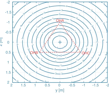
3.10 SNR as a function of centre of mass position relative to optical heads . . . . 50
3.11 Passive acquisition concept for multi-link GRACE . . . 52
List of Figures
4.1 Cycle slipping in a phase locked loop . . . 57
4.2 Linear approximation of phasemeter . . . 58
4.3 Gaussian phase error and the probability of cycle slipping . . . 60
4.4 Probability of cycle slipping . . . 61
4.5 Frequency response of open loop phasemeter gain . . . 62
4.6 Standard deviation of phase error due to shot noise and laser frequency noise 64 4.7 Standard deviation of phase error due to shot noise and laser frequency noise 65 4.8 Experimental setup for low SNR phase tracking experiment . . . 67
4.9 Cycle slip in a 30 fW phase measurement . . . 69
4.10 Measured mean-time to cycle slip . . . 70
5.1 Time delay interferometry example . . . 75
5.2 Time delay interferometry in LISA . . . 76
5.3 Proposed test of time delay interferometry on GRACE-FO . . . 78
5.4 Optical configuration in GRACE-FO time delay interferometry test . . . 79
5.5 Time delay interferometric ranging in GRACE-FO . . . 81
5.6 RMS displacement across the GRACE-FO measurement band . . . 82
5.7 Algorithm for tone assisted TDIR demonstration . . . 83
5.8 Suppression of laser frequency displacement noise in simulated tone assisted TDIR . . . 87
5.9 Error in the range fit from simulated tone-assisted TDIR . . . 89
5.10 Relationship between data length, modulation depth and range error in tone-assisted TDIR . . . 90
5.11 Optical layout of the benchtop TDIR experiment . . . 91
5.12 Displacement signal injection in benchtop TDIR experiment . . . 92
5.13 Suppression of laser frequency displacement noise in benchtop TDIR exper-iment . . . 95
6.1 Simple experiment to test the multi-link concept . . . 98
6.2 Early GRIN lens based optical head prototype . . . 99
6.3 Approximation of a 3 element optical head . . . 100
6.4 Optical head approximation . . . 101
6.5 Optical layout for proof of principle experiment . . . 102
6.6 Suppressing spurious reflections with DEHI . . . 103
6.7 Real-time signal processing in proof of principle experiment . . . 106
6.8 DEHI code acquisition along link A . . . 107
6.9 Estimating the ‘interspacecraft’ displacement . . . 108
List of Figures
6.11 Modelling pitch and yaw with a fast steering mirror . . . 112
6.12 Changing the rotation-to-pathlength coupling strength . . . 113
6.13 One-way, round-trip and centre of mass displacement measurements along links B and C . . . 114
6.14 One-way and centre of mass displacement measurements along links A, B and C . . . 117
6.15 Optical head configuration captured using CCD camera beam profiler . . . 120
6.16 Comparison of signal beam and optical head beam . . . 120
7.1 Predicted one-way link noise in multi-link GRACE . . . 128
7.2 Predicted noise in the centre of mass displacement in a multi-link GRACE . 133
8.1 An alternate multi-link GRACE implementation . . . 140
8.2 Input and output interfaces of the waveguide optical head . . . 142
8.3 Waveguide optical head . . . 143
8.4 Using the multi-link architecture for multi-degree of freedom test mass readout144
List of Tables
5.1 Tone assisted TDIR simulation parameters . . . 85
6.1 Summary of injected noise and signal tones . . . 104
6.2 Noise suppression in 1-link measurement . . . 110
6.3 Weights used to suppress yaw in 2-link measurements . . . 115
6.4 Comparison of noise suppression in 2-link measurements . . . 116
6.5 Weights used to minimise pitch and yaw in 3-link measurement . . . 118
6.6 Comparison of pitch and yaw in post-processing combinations . . . 119
6.7 Noise suppression in 3-link measurement . . . 121
7.1 Summary of assumed link displacement noise spectra . . . 127
Chapter 1
Candidate laser interferometer
architecture for next generation
GRACE
The Gravity Recovery and Climate Experiment Follow-On (GRACE-FO) mission will include the first demonstration of interspacecraft laser interferometry [1], starting a new era of precision space-based metrology. GRACE-FO continues the geodesy mission started by GRACE [2]. Since it launched in 2002, GRACE has been monitoring time and spatial variations in Earth’s geoid. The GRACE data has provided valuable insights into the large scale motion of water, leading to an extensive body of climate change research [3–5].
GRACE uses a microwave ranging instrument [6] to track the displacement between two spacecraft in a shared, low-Earth orbit. The displacement measured with the microwave instrument has a 1 µm/√Hz noise floor. Since GRACE launched, many [7–11] have considered how a next generation GRACE could employ a laser link to improve this sensitivity. GRACE-FO will again use a microwave instrument, however it will also include a laser interferometer as a technology demonstration [12]. With a predicted displacement noise sensitivity of 90 nm/√Hz [1], the GRACE-FO laser ranging interferometer will affirm the technology’s value for a next generation GRACE mission and for future interferometry missions in general.
Space-based interferometers face different challenges compared with their lab-based coun-terparts and therefore traditional interferometer designs must be rethought. The inter-ferometers need to survive high accelerations and vibrations during launch since, once launched, they cannot be repaired without great cost. The interferometers therefore demand a reliability and robustness, that is not needed from an interferometer used in a controlled lab environment. A number of challenges had to be overcome during the development of the GRACE-FO laser interferometer including: link acquisition [13, 14]; laser frequency equivalent displacement noise suppression [12, 15]; and rotation-to-pathlength coupling [16–19]. Decades of work has gone into adapting lab-based interfer-ometry techniques to solve similar problems in other space-based laser interferometers, such as LISA [20], ASTROD [21] and DECIGO [22], driving their cost and complexity.
1.1 Rotation-to-pathlength coupling in an interspacecraft laser interferometer
with an overview of the thesis, outlining the experiments and analysis that have been performed, in order to evaluate the proposed architecture.
1.1
Rotation-to-pathlength coupling in an interspacecraft
laser interferometer
GRACE-FO will use a microwave instrument to measure the change in displacement along two one-way links between spacecraft. The basic measurement concept is illustrated in Figure 1.1. The separation between the two GRACE-FO spacecraft is on the order of 200 km. As they orbit the Earth, mass anomalies will cause the interspacecraft separation xR(t) between the two spacecraft to be modulated, since the spacecraft experience the gravitational forces at different times. The displacement measurement is also affected by the tides, atmospheric drag and the ionosphere [24]. To extract the gravitational information, the raw displacement measurements made on each spacecraft have to be transmitted to the ground for post-processing [6]. Combining information from GPS [24], accelerometers [25] and spacecraft attitude measurements from star cameras [26] a number of corrections are made to remove these non-gravitational effects [27].
Spacecraft rotation can also couple into the interspacecraft displacement measurement. A lateral offset in the microwave link from the line-of-sight between the spacecraft centres of mass will lead to spacecraft rotation coupling into the displacement measurement. In GRACE, the microwave ranging instrument is positioned along the line-of-sight between the accelerometers in order to reduce the coupling of spacecraft attitude jitter into path-length. Precise measurements of spacecraft attitude from the star cameras [28] are used to correct the displacement measurements to further minimise the effects of any rotation-to-pathlength coupling.
Since the GRACE-FO laser ranging interferometer is a technology demonstration, it must not interfere with the primary microwave instrument. Consequently, the laser link cannot be positioned along the line-of-sight. Figure 1.2 illustrates the sensitivity to rotation if the laser link is offset from the line-of-sight. In the figure, the laser link between spacecraft 1 and spacecraft 2 is offset a distancedfrom the line-of-sight between the spacecraft centres of mass. The link is used to measure displacement between the centre of mass plane1 on spacecraft 1 and thecentre of mass plane on spacecraft 2. An angular misalignment due to a spacecraft rotation, θ(t), introduces a first order optical path length error of:
∆xtilt(t) =dsinθ(t) (1.1)
The coupling strength is directly proportional to the offset from the line-of-sight.
The GRACE-FO laser ranging interferometer has been designed to use symmetry to min-imise the rotation-to-pathlength coupling in the interspacecraft displacement. The inter-ferometer will route the laser around the microwave ranging instrument using the triple mirror assembly (TMA)2, a system of three mirrors that routes the beam symmetrically either side of the spacecraft centre of mass. Provided the triple mirror assembly is placed so that its vertex coincides with the spacecraft centre of mass, any rotation will be can-celled due to the symmetry of the paths. The challenge then becomes integrating the laser
1While the centre of mass is a point and therefore does not define a plane, centre of mass plane is
used throughout this thesis to describe the plane through the centre of mass that is orthogonal to the line-of-sight between spacecraft.
Chapter 1 Candidate laser interferometer architecture for next generation GRACE
SC1 SC2
orbit
Fg Fg
xR(t)
one-way links
groundwater
(a) GRACE spacecraft passing mass anomaly
SC1 SC2
xR(t)
Fg Fg
orbit
depleted groundwater one-way links
depleted groundwater
[image:23.595.165.486.348.565.2](b) The GRACE spacecraft passing uniform mass
Figure 1.1: The GRACE measurement concept [23]. In (a) the spacecraft are shown passing over a region with groundwater. Both spacecraft will experience a similar gravitational attraction
to the groundwater Fg. The delay between the spacecraft mean they experience the gravitational
1.2 A new laser interferometer architecture for a next generation GRACE
d
θ(t)
line-of-sight
laser link c.m
SC1
xR(t)
z x
y
SC2
c.m plane SC1
c.m
rotated c.m plane SC2
unrotated c.m plane SC2
Figure 1.2: If a laser link between two spacecraft is offset from the line-of-sight between the
spacecraft centres of mass (c.m) by a distance d, a rotationθ(t) of either spacecraft will introduce
a first order pathlength error ∆xtilt(t) =dsinθ(t) to the displacement measurement. Higher order
errors are discussed in Chapter 3.
ranging interferometer with the rest of the spacecraft to within the tight tolerances – the vertex needs to be positioned within 0.5 mm of the spacecraft centre of mass to achieve the required displacement sensitivity [17].
1.2
A new laser interferometer architecture for a next
generation GRACE
Multi-link interferometry has been developed to ease the spacecraft integration and re-lax the requirements on positioning and alignment while still enabling the cancellation of rotation-to-pathlength coupling. To explain the multi-link concept, the simple space interferometer shown in Figure 1.2 is again considered, but this time, a second laser link is added. The result is shown in Figure 1.3. Measuring the displacement along both links provides a way to disentangle the spacecraft rotation from the spacecraft displacement. In this example, the two laser links, which are denoted A and B, are positioned symmetrically either side of the spacecraft centre of mass. A relative rotation of spacecraft 2 byθ(t) will result in an anti-symmetric lengthening and shortening of the two laser links. Measuring the displacement along link A, xA(t), and link B, xB(t), provides two measurements of the spacecraft displacement, xR(t), with anti-symmetric measurements of the spacecraft rotation-to-pathlength coupling, ∆xtilt(t):
xA(t) =xR(t)−∆xtilt(t) (1.2) xB(t) =xR(t) + ∆xtilt(t) (1.3) Since the links are symmetric, averaging the two measurements cancels the spacecraft rotation coupled displacement error, and the interspacecraft displacement is recovered:
xc.m(t) = 1
Chapter 1 Candidate laser interferometer architecture for next generation GRACE
d
∆xtilt(t)
θ(t) line-of-sight
laser link B c.m
SC1
xR(t)
z x
y SC2
laser link A
-∆xtilt(t)
A
B
A
B
c.m plane SC1
c.m
rotated c.m plane SC2
unrotated c.m plane SC2
Figure 1.3: Multi-link interferometry concept. With multiple laser link measurements between spacecraft it is possible to sense the multiple degrees of freedom that affect the spacecraft displace-ment measuredisplace-ment. Two laser links are shown, A and B, placed symmetrically either side of the
spacecraft center of mass (c.m), offset by ± d in the plane passing through the centre of mass,
orthogonal to the line of sight. Taking an average of the displacement measured along each link, an estimate of the centre of mass displacement can be synthesised.
The use of symmetry in this multi-link example is similar to the cancellation of rotation in the TMA. The main advantage of the multi-link architecture however is that the multiple link measurements are combined in post-processing, as opposed to optically in the TMA. Consequently, when the measurements are added, their relative weights can be varied. Provided they are in the plane of the centre of mass, any arrangement of links between spacecraft can be used to measure the interspacecraft displacement. The weights can then be optimised to synthesise the centre of mass displacement and completely cancel the rotation-to-pathlength coupled error. This allows drastically larger uncertainty in the positioning of the links, easing the spacecraft integration by relaxing the requirements on positioning and alignment. In this respect the technique is also similar to the corrections applied to the GRACE microwave ranging data.
An all-fibre multi-link GRACE concept architecture is shown in Figure 1.4. Constructed entirely in fibre, the interferometer will be compact, minimising the size and mass, and simplifying spacecraft integration further. To cancel the rotation coupled error due to rotation of both spacecraft, more than 2 laser links are needed. A multi-link GRACE would need at minimum 9 interspacecraft links to cancel both pitch and yaw coupled displacement error. In the concept architecture shown, this is achieved using 3 fibre-coupled optical heads per spacecraft. Forming links between all optical head pairs on the two spacecraft, and measuring displacement at both ends of each link, provides 18 independent measurements of the interspacecraft displacement.
rotation-to-1.3 Thesis outline
θpitch1(t)
laser 1
detector 1
xR(t)
optical head
interspacecraft links
c.
m
p
la
n
e
SC
1
θpitch2(t)
c.
m
p
la
n
e
SC
2
z x
y
laser 2
detector 2
θyaw1(t) θyaw2(t)
spacecraft 1
(SC1)
spacecraft 2
(SC2)
optical fibre
Figure 1.4: Multi-link GRACE concept architecture. The all-fibre architecture is shown for both spacecraft. A minimum of 9 interspacecraft links are needed to cancel pitch and yaw coupled error from both spacecraft. The links are formed between 3 optical heads positioned arbitrarily within the plane of the centre of mass on each spacecraft. Combining the 18 link measurements in
post-processing, the centre of mass displacement,xR(t), can be recovered.
pathlength coupled noise using a weighted average of multiple link measurements, has to be tested.
Recent advances in moving the complexity of interferometry into signal processing make this architecture feasible [29–31]. In Chapter 3 a more detailed multi-link GRACE architec-ture will be presented that uses digitally enhanced heterodyne interferometry (DEHI) [32] for multiplexing, relies on only star camera alignment for link acquisition, and uses time delay interferometry (TDI) [33] for laser frequency displacement noise suppression. Sev-eral aspects of this design however require testing and will be the focus of this thesis. The major challenges of the multi-link architecture addressed in this thesis are:
1. Cancelling rotation-to-pathlength coupling in a weighted average
2. Tracking the phase of optical signals with low SNR
3. Suppressing frequency displacement noise with TDI in GRACE
1.3
Thesis outline
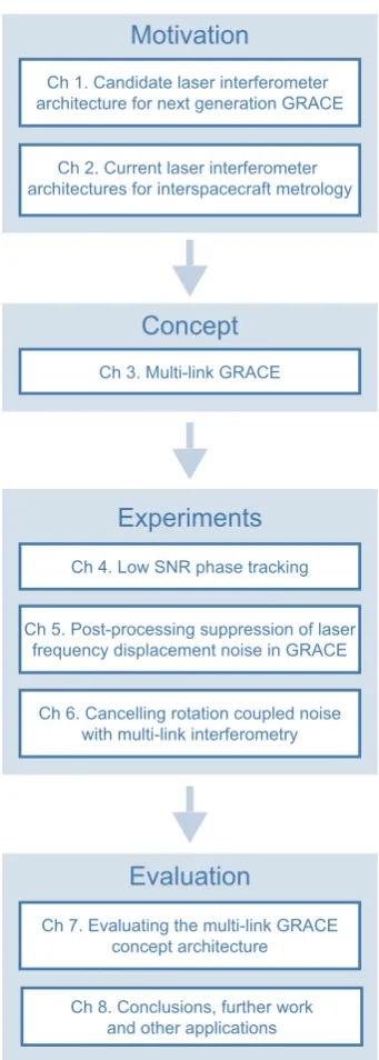
The aim of this thesis is to evaluate the proposed multi-link architecture and determine whether it is an appropriate candidate for a next-generation GRACE mission. The thesis outline is shown in Figure 1.5.
Chapter 1 Candidate laser interferometer architecture for next generation GRACE
Motivation
Concept
Experiments
Evaluation
Ch 1. Candidate laser interferometer architecture for next generation GRACE
Ch 2. Current laser interferometer architectures for interspacecraft metrology
Ch 3. Multi-link GRACE
Ch 4. Low SNR phase tracking
Ch 5. Post-processing suppression of laser frequency displacement noise in GRACE
Ch 6. Cancelling rotation coupled noise with multi-link interferometry
Ch 7. Evaluating the multi-link GRACE concept architecture
[image:27.595.240.411.166.644.2]Ch 8. Conclusions, further work and other applications
1.4 Publications
With this background established, in Chapter 3 a detailed multi-link GRACE architecture is presented. The signal processing required to transform multiple one-way link measure-ments into a round-trip displacement measurement between spacecraft centres of mass is explained. Some of the effects that could potentially limit the displacement sensitivity of the interferometer are then highlighted. This leads to a discussion of the main challenges of the multi-link architecture.
In Chapters 4-6 three experiments are presented that have been used to verify the multi-link concept, addressing these challenges.
In Chapter 4 the first of these experiments is described: an experimental demonstration of phase tracking a low signal-to-noise ratio (SNR) signal. Chapter 5 reports on the development of a potential laser frequency displacement noise suppression test using time delay interferometry on GRACE-FO. Then, in Chapter 6, a proof of principle experiment is presented where the simulated pitch and yaw of a spacecraft is suppressed using a weighted average, in the first demonstration of a multi-link interferometer.
In Chapter 7, based on the results of these three investigations, the multi-link architecture is evaluated, the displacement sensitivity of a multi-link GRACE is predicted and the remaining work that needs to be performed before the architecture can be realised on a next-generation GRACE mission is outlined.
Chapter 8 concludes the thesis, highlighting the major contributions of this work. The further work required to realise a multi-link GRACE is discussed in more detail and some other applications of the multi-link architecture are briefly discussed.
1.4
Publications
Publications directly related to the work in this thesis are as follows:
S.P. Francis, T.T-Y. Lam, K. McKenzie, A.J. Sutton, R.L. Ward, D.E. McClelland, and D.A. Shaddock, “Weak-light phase tracking with a low cycle slip rate,” Optics letters
39(18), 5251—5254 (2014).
S.P. Francis, D.A. Shaddock, A.J. Sutton, G. deVine, B. Ware, R.E. Spero, W.M. Klip-stein, and K. McKenzie,“Tone-assisted time delay interferometry on GRACE Follow-On,” Physical Review D 92(1), 012005 (2015).
Chapter 2
Current laser interferometer
architectures for interspacecraft
metrology
Before studying the multi-link interferometry concept in detail, the measurement principles behind two missions – LISA and GRACE-FO – are first explained. The heterodyne laser interferometry technique at the core of both measurement schemes is introduced and some of the techniques that can be used to extend the capabilities of the heterodyne technique are described. The chapter ends with a discussion of the main noise sources limiting the displacement sensitivity of the two missions. The aim is to provide the reader with a point of comparison for the discussion of the multi-link interferometer in the next chapter as well as introduce the language and notation that will be used throughout this thesis when analysing interferometers.
2.1
LISA and the GRACE-FO laser ranging interferometer
Well before the detection of gravitational waves with LIGO [34], space-based gravitational wave observatories, such as LISA [20], have been under development as a way to probe the low frequency – mHz to Hz – gravitational wave sources outside the band of terrestrial detectors. Operating in space, LISA will benefit from longer arm lengths and isolation from seismic and other terrestrial noise sources currently limiting the low frequency – 10 Hz and below – sensitivity of LIGO. Without these limiting sources, a LISA-like mission will potentially detect gravitational waves from black hole mergers, such as GW150914, weeks and even months before the actual collision [35].
Like the LIGO interferometer [36], LISA will detect gravitational waves by measuring the displacement of inertial test masses at the ends of two arms of a Michelson interferometer. Most LISA concepts use a constellation of three spacecraft, with separations on the order of 1 million kilometres, and two-way laser links between each adjacent spacecraft pair. On each spacecraft there will be two test masses, allowing three Michelsons to be formed from the six inter-spacecraft links.
2.2 Measuring interspacecraft displacement
SC1
SC3 SC2
~ 1
mi llio
n km lase
r li nks
(a)LISA constellation
SC1 SC2
~ 200 km
laser links
(b) GRACE-FO constellation
Figure 2.1: The LISA and GRACE-FO missions. Both interferometers use two-way laser links between spacecraft to measure the change in separation. In LISA, the links are ultimately meas-ured between inertial masses on each spacecraft while GRACE-FO will measure displacement between the spacecraft themselves. LISA has three spacecraft with arms around 1 million kms while GRACE-FO consists of two spacecraft with a separation on the order of 200 km.
spacecraft [39]. In Pathfinder, the relative acceleration noise between two free-falling ref-erence test masses was measured to be as low as (0.54±0.01)×10−15 g/√Hz across the LISA band. Other missions, including GRACE-FO and Gaia [40], have also provided opportunities to test aspects of the LISA architecture [38].
The GRACE-FO laser ranging interferometer design benefited directly from LISA work. Consequently the laser ranging interferometer shares several aspects of the proposed LISA measurement scheme, namely: laser pre-stabilisation, MHz Doppler shifts, a received power around 100 pW, and a heterodyne displacement measurement using a digital phase-locked loop. Development of the laser ranging interferometer can therefore be used to inform the implementation of the displacement measurement system and laser frequency reference cavity for LISA [38].
Figure 2.1 compares the LISA and GRACE-FO missions. While the two missions have similar measurement concepts, their scales differ by many orders of magnitude necessit-ating different techniques. In the next section, the displacement measurement techniques used by both LISA and GRACE-FO are introduced. In Chapter 5 some of the addi-tional techniques - Time Delay Interferometry and Arm locking - required on LISA, are described.
2.2
Measuring interspacecraft displacement
Both LISA and GRACE-FO use heterodyne interferometry and a digital implementation of a phase-locked loop to track the interspacecraft displacement.
The phase, φ(t), of an optical field scales with the optical pathlength. Therefore a laser link between spacecraft with an interspacecraft displacement, xR(t), will have a phase change:
φ(t) = 2π
f t+xR(t) λ
[rad] (2.1)
Chapter 2 Current laser interferometer architectures for interspacecraft metrology
Displacement interferometry can be used for not only precision measurements of path-length but also changes in optical wavepath-length [41], refractive index [42], velocity [43] and even rotation [44]. This section explains how LISA and GRACE-FO use displace-ment interferometry and signal processing to track changes in the separation between two spacecraft.
2.2.1 Heterodyne displacement interferometry
Laser frequencies are typically hundreds of terahertz and are therefore too fast for the phase of the optical field to be measured directly. Instead, heterodyne interferometry can be used to infer the phase of the optical field. Heterodyne interferometry compares the optical frequency of a signal laser with the optical frequency of a local oscillator field. A laser carrying the displacement signal can be interfered with a local, frequency offset laser, shifting the signal down to a more manageable radio frequency (RF). An RF signal is within the sampling rate of digital systems allowing the phase to then be extracted using digital signal processing.
A frequency offset, fhet, between the two lasers will result in a beatnote at fhetwhen the signal and local oscillator fields interfere. The beatnote phase encodes the optical phase of the interfering fields; a change of 1 cycle in the displacement signal results in a 1 cycle change in the beatnote phase. The detected beatnote will change from constructive to destructive interference millions of times a second, modulating the laser power on the detector.
E
LO(t)
detector
local oscillator
laser
beamsplitter
FPGA
digital signal processing
V
het(t)
E
sig(t)
Figure 2.2: Heterodyne interferometry in LISA and GRACE-FO. Both LISA and GRACE-FO use
heterodyne interferometry to infer the spacecraft displacement. The weak signal beam, Esig(t),
arriving from the distant spacecraft is interfered with a bright, frequency offset local oscillator
ELO(t) using a beamsplitter. The resulting beatnote measured by the photodetector is tracked in
digital signal processing on a Field Programmable Gate Array (FPGA) to recover the displacement signal.
Figure 2.2 shows an example heterodyne interferometer. In the figure, a signal laser with electric field:
Esig(t) =
p
2.2 Measuring interspacecraft displacement
ELO(t) =
p
Ploei(2πfLOt+φLO(t)) (2.3) The interference between the two fields is measured by the photodetector. The detector outputs a voltage, Vhet(t), proportional to the power of the detected light:
Vhet(t)∝PLO+Psig+ 2
p
PLOPsigcos(2πfhett+φhet(t)) (2.4) The photodetector output, Vhet(t), is proportional to the DC power of the interfering local oscillator and signal lasers,PLOandPsig1 respectively, and an interference term that oscillates at the difference frequency: fhet = fLO−fsig. Most importantly, the phase of the beatnote,φhet(t) =φlo(t)−φsig(t), is proportional to the phase of the signal.
LISA and GRACE-FO both use heterodyne interferometry to measure the interspacecraft displacement. In some respects this is necessary: the relative motion of the spacecraft will doppler shift the signal frequency by a few MHz [1]. There are other advantages to using heterodyne interferometry however. The signal coming from the distant spacecraft will be low power (pW) when it arrives at the detector. As a coherent technique, the heterodyne interference between the low power signal and a high power (mW) local oscillator, will amplify the signal above the detector noise floor. This increases the dynamic range of the measurement, changing the measurement from a technical noise limited measurement to a quantum noise limited measurement. Compared with homodyne interferometry, hetero-dyne interferometry also isolates the measurement from low frequency laser and electronic noise.
2.2.2 Phasemeter displacement measurements
Following detection the beatnote is digitised using an Analog-to-Digital Converter (ADC) and then processed on a Field-Programmable Gate Array (FPGA). The interspacecraft displacement can be determined by measuring the phase of the heterodyne beatnote with a phasemeter [45, 46], a linear phase tracker that has been experimentally verified to have a dynamic range over 9 orders of magnitude [47].
An example phasemeter is shown in Figure 2.3. The phasemeter is able to track the heterodyne phase by locking the phase of a numerically controlled oscillator (NCO) to the detected beatnote. The phase of the NCO then provides a measurement of the heterodyne phase.
The NCO is locked to the heterodyne beatnote by feeding back the phase error between the two signals to the NCO phase. The NCO output, NCOout, is of the form:
NCOout = cos(2πfNCOt) (2.5)
wherefNCO is the frequency of the NCO.
The phase error between the beatnote and the NCO is determined by multiplying the signals using a mixer and then low pass filtering. Using Eq. 2.4 and Eq. 2.5, the mixer output Mout(t) is:
Mout(t) = sin(2π∆fdifft+ ∆φdiff(t)) + sin(2π∆fsumt+ ∆φsum(t)) (2.6)
Chapter 2 Current laser interferometer architectures for interspacecraft metrology
integrator
∫
het
(t)
LPF
NCO
controller
mixer
P
het(t)
PI
f
NCOf
corr(t)
^
adder
^
M
out(t)
NCO
out(t)
LPF
out(t)
f
NCO(t)
Figure 2.3: The phasemeter effectively contains a narrow bandpass filter that tracks the frequency
of the heterodyne beatnote. The digitised detector output, Phet(t), is mixed with a numerically
controlled oscillator (NCO). The output of the mixer is low pass filtered (LPF) to determine the
phase error between the beatnote and NCO fcorr. The estimated NCO frequency, ˆfNCO, is then
updated using the correction with feedback provided via a proportional-integral (PI) controller. In
steady-state the NCO phase, ˆφhet(t), is locked to the heterodyne phase, φhet(t), π/2 radians out
of phase.
A component of the mixer output is at the difference frequency, ∆fdiff =fNCO−fhet, and the other at the sum frequency, ∆fsum = fNCO+fhet. The DC power terms (PLO and Psig) in Eq. 2.4 have been ignored. These terms do not contain any phase information and can therefore be low pass filtered in the analog electronics before the FPGA, without affecting the displacement measurement.
The low pass filter (LPF) in the phasemeter is used to remove the sum frequency term in the mixer output. The output of the low pass filter LPFout(t) is proportional to:
LPFout(t)∝sin(2π∆fdifft+ ∆φdiff(t)) (2.7) where ∆φdiff(t) =φnco(t)−φhet(t).
Ideally the NCO frequency equals the heterodyne frequency and the output of the low pass filter is proportional to the phase difference. If the frequencies are not equal, the phasemeter will still be able to track the heterodyne signal, provided the frequency dif-ference is within the pull-in range of the phasemeter [48]. In steady-state, the NCO will then have the same frequency as the heterodyne beatnote, and the filter output will be proportional to the heterodyne phase:
LPFout(t) = sin(∆φdiff(t))≈∆φdiff(t) (2.8)
assuming the phase error is small. The phase error is used to update the frequency of the NCO to lock it to the heterodyne beatnote. A proportional-integral controller (PI) is used to set the bandwidth of the feedback. The output of the controller is used as a frequency correction fcorr(t) to update the NCO. The NCO tracks the phase of the heterodyne beatnote,π/2 radians out of phase. When the NCO is tracking the heterodyne signal, the phase of the NCO can be used to estimate the heterodyne phase, ˆφhet, and therefore the interspacecraft displacement, xR(t):
2.3 Limiting noise in an interspacecraft displacement measurement
2.3
Limiting noise in an interspacecraft displacement
measurement
There are many reasons why traditional optical interferometry techniques are difficult in space. Mass, alignment, fitting optics around other space hardware and building optics that can survive launch, are just a few of the challenges.
The long interferometer arms in space-based interferometers, although increasing the sens-itivity to signals, also increase the susceptibility to laser frequency noise, make it harder to acquire a laser link between spacecraft and, because of beam diffraction, limit the amount of optical power reaching the distant spacecraft.
In this section the noise sources that limit the displacement sensitivity of space-based interferometers are discussed and techniques that can be used to minimise their impact are introduced.
2.3.1 Spurious reflections, cyclic error and digitally enhanced heterodyne interferometry
Spurious reflections can occur at all glass-air interfaces in an interferometer, potentially adding cyclic noise to the displacement measurement. Although the intensity of these reflections can be minimised using coatings, angle polished fibres and careful alignment of the interferometer, they are difficult to remove completely. Spurious reflections can interfere with the other signals in an interferometer leading to additional beatnotes on the photodetector. Depending on the frequency and relative size of these beatnotes compared with the main heterodyne signal, they can greatly limit the phasemeter’s ability to track the true heterodyne phase.
In a heterodyne interferometer, the spurious reflections will most likely be at the same frequency as the local oscillator or signal fields. Since the local oscillator power is typically orders of magnitude larger than the signal power, the spurious beatnotes of most concern in a space-based interferometer will be from the spurious local oscillator reflections interfering with the local oscillator and signal field. The spurious local oscillator-local oscillator beatnotes will be at DC while the spurious local oscillator-signal beatnotes will be at the heterodyne frequency.
Chapter 2 Current laser interferometer architectures for interspacecraft metrology
frequency [Hz]
d
e
te
ct
o
r
o
u
p
u
t
[V]
spurious beatnote
heterodyne signal
phasemeter filter response
[image:35.595.220.430.90.346.2]DC fhet
Figure 2.4: Phasemeter suppression of signals outside the passband. The phasemeter contains a narrow bandpass filter that tracks the heterodyne signal. Spurious signals at other frequencies, such as the spurious local oscillator-local oscillator beatnote at DC, will be attenuated by the low pass filter.
hete
rodyn
e
ω
het ɸhet(t)sp uri
ou s
∆ɸcyclic
Re
Im
sp uri
ou s
∆ɸpath(t)
Figure 2.5: A phasor diagram in the frame of the heterodyne beatnote showing the effect of
parasitic interference on the phase measurement. The beatnote phase isφhethowever the spurious
reflection has a phase difference, ∆φpath(t), adding a phase uncertainty, ∆φ, related to the relative
amplitudes of the spurious signal and heterodyne beatnote. Since both the heterodyne beatnote
and the spurious local oscillator-signal beatnote have powers proportional topPsigthe cyclic error
[image:35.595.220.433.453.656.2]2.3 Limiting noise in an interspacecraft displacement measurement
Cyclic error and its effect on the heterodyne displacement measurement is illustrated in Figure 2.5. The spurious beatnote and heterodyne beatnote are represented as phasors. The frame is rotating at ωhet with the heterodyne signal. The spurious beatnote adds an uncertainty at the end of the heterodyne phasor. The uncertainty is related to the relative amplitudes of the spurious signal and heterodyne beatnote and evolves as the relative pathlength difference, ∆xpath(t), between the two beatnotes changes. The spurious local oscillator-signal beatnote at the heterodyne frequency will introduce a cyclic error, δx˜cyclic(f), proportional to the ratio of the spurious and heterodyne beatnote:
δx˜cyclic(f)∝
p
PscatterPsig
p
PLOPsig =
r
Pscatter PLO
(2.10)
where Pscatter is the power of the the spurious local oscillator reflection, PLO is the local oscillator power and Psig is the power of the signal field. The cyclic error is independent of the signal power.
If the relative pathlength fluctuations, δx˜path(f), between the source of the spurious re-flection and the local oscillator are much less than a cycle the root-power spectral density of the cyclic noise can be approximated by [53]:
δx˜cyclic(f)≈
r
Pscatter PLO
δx˜path(f)
m
√
Hz
(2.11)
When the relative pathlength fluctuations increase beyond a cycle, as Figure 2.5 shows, the cyclic error saturates. The maximum cyclic error will be:
δx˜cyclic(f)≤λ
r
Pscatter PLO
m
√
Hz
(2.12)
Although it will be susceptible to spurious interference, the impact of cyclic error will be minimised passively in LISA by mounting the optics on an ultra low expansion glass breadboard with a pathlength stability of a few pm/√Hz [54].
To simplify the interferometer design a multi-link GRACE would ideally not need an ul-trastable optical bench. Fortunately, there exist active techniques to suppress the spurious reflections. One method is to dither the source of the scattering, shifting the frequency of the spurious phase noise outside the measurement band [53, 55]. Another option is to use digitally enhanced heterodyne interferometry (DEHI) [32], a technique that can isolate signals based on their time of flight.
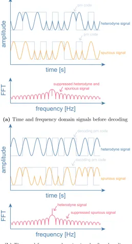
With DEHI it is possible to recover the phase of a heterodyne signal while suppressing the effect of spurious reflections. The technique uses pseudo random optical phase modulations to produce spread spectrum signals. In digital signal processing the same pseudo random codes can be applied to decode specific signals while leaving unwanted reflections as spread spectrum and therefore suppressing their contribution to the phase error.
Chapter 2 Current laser interferometer architectures for interspacecraft metrology
time [s]
a
mp
lit
u
d
e
heterodyne signalfrequency [Hz]
F
F
T
spurious signal
prn code
prn code
suppressed heterodyne and spurious signal
(a) Time and frequency domain signals before decoding
time [s]
a
mp
lit
u
d
e
heterodyne signalfrequency [Hz]
F
F
T
spurious signal
decoding prn code
decoding prn code
heterodyne signal
suppressed spurious signal
[image:37.595.198.457.82.558.2](b)Time and frequency domain signals after decoding
2.3 Limiting noise in an interspacecraft displacement measurement
appear as broadband noise. In (b), a local copy of the pseudo random code has been used to remove the modulation from the heterodyne signal. Matching the delay to the code delay on the heterodyne beatnote, it is possible to recover the heterodyne signal. The spurious reflection, which has a different code delay, remains modulated. In the frequency domain, the heterodyne signal can be seen along with the broadband noise that remains from the suppressed spurious signal.
The amount of suppression depends on a number of factors. The length of the code is an important factor. In most DEHI implementations, a maximum length sequence (m-sequence) is used as the pseudo random code [29, 32, 56]. An m-sequence is a pseudo random binary sequence generated using linear feedback shift registers and is chosen be-cause of its autocorrelation properties. A m-sequence code of length N will have an auto-correlation peak with an amplitude of N. The autoauto-correlation will be -1 when the delays are not matched. Summing over a code length should suppress spurious signals by N, however, the second harmonic in the phasemeter measurement degrades the suppression to approximately:
DEHI suppression≈√N (2.13)
The exact suppression depends on the ratio of the heterodyne frequency and pseudo-random noise code chip frequency [32].
DEHI is only able to distinguish between reflections that occur in different chips. A chip is the shortest sample of the m-sequence. The chip frequency, which is how frequently the code changes state, will determine the smallest separation that the DEHI can distinguish between. For chip frequency,fc, and speed of light,c, DEHI will only be able to distinguish
between reflections with pathlength differences:
∆x > c fc
[m] (2.14)
In practice the amount of suppression can also be affected by non-linear effects in the phase modulation and detection of the beatnotes. Therefore it is common practice to have several chips of isolation between reflections to avoid cross-coupling between adjacent chips.
In addition to suppressing spurious signals DEHI has other uses. The phasemeter is sensitive to changes in optical pathlength however it is unable to measure absolute lengths. Since DEHI can isolate signals based on their time of flight it can therefore be used to measure absolute length [57]. Provided the signals have different time of flight delays (or even orthogonal codes) DEHI can also be used to multiplex signals on the one detector [29].
2.3.2 Laser frequency noise
While DEHI is not part of any current mission designs, pseudo random noise will be used in LISA to assist in the determination of the interspacecraft delays needed for some of its laser frequency displacement noise suppression techniques [57].
Chapter 2 Current laser interferometer architectures for interspacecraft metrology
∆x x =
∆ν
ν (2.15)
That is, for a spacecraft separation, x, a change in the separation of the spacecraft, ∆x, will be indistinguishable from a fluctuation, ∆ν, in the laser frequency, ν. The larger the spacecraft separation, the larger the displacement noise due to laser frequency noise.
The GRACE-FO laser ranging interferometer uses an Nd:YAG non-linear planar ring oscillator (NPRO) laser with a wavelength of 1064 nm [12]. A free-running NPRO laser typically has frequency noise with a root-power spectral density [59]:
δν˜NPRO =
3×10⁴ f
Hz
√
Hz
(2.16)
Therefore with a spacecraft separationx= 200 km and laser frequencyν ≈2.8×10¹⁴ Hz, the free-running noise would introduce a displacement noise equivalent to:
δx˜NPRO(f)≈ 20
f
µm
√
Hz
(2.17)
This is almost three orders of magnitude larger than the required displacement sensitiv-ity [1]. To limit the effect of the laser frequency noise on the displacement measurement, the laser ranging interferometer will lock the frequency of the laser to a stable reference cavity [12]. Optical cavities can be constructed by mounting mirrors on the ends of a ‘spacer’ made from a material with a low thermal expansion coefficient such as ultra low expansion glass or Zerodur [12]. The length stability of such cavities is a lot higher than the equivalent frequency stability of a free-running NPRO laser. They therefore provide a good frequency reference for laser frequency stabilisation. Using a cavity locking technique such as Pound-Drever-Hall [60], the stability of the cavity can be transferred to the laser frequency.
The GRACE-FO laser ranging interferometer cavity will provide a frequency stabilised laser with a root-power spectral density [12]:
δν˜StabNPRO(f) = 30
Hz
√
Hz
(2.18)
This leads to a more acceptable displacement equivalent noise in GRACE-FO around 20 nm/√Hz. Figure 2.7 compares the displacement equivalent noise from free-running and frequency stabilised lasers with the required laser ranging interferometer displacement sensitivity. In reality the frequency stabilisation has to only be at the 30 Hz/√Hz level across the 10 mHz to 100 mHz measurement band. The design sensitivity is shaped with a noise shaping function [61, 62] to reflect this requirement.
In GRACE-FO only one laser will be stabilised because otherwise the heterodyne beatnote can not be guaranteed to be within the detector bandwidth. Instead, the second laser will be offset phase locked to the stabilised laser, transferring the stability of the stabilised laser to the free-running laser. Phase locking uses a similar feedback loop control as the phasemeter. The difference is that the actuation is now on laser frequency, rather than a numerically controlled oscillator, and the phase discriminator is a phasemeter.
2.3 Limiting noise in an interspacecraft displacement measurement
10 -4 10 -3 10 -2 10 -1 10 0 101 10-9
10-8 10-7 10-6 10-5 10-4 10-3 10-2 10-1 100
frequency [Hz]
di
sp
la
ce
me
nt
[m/
√H
z]
(30 Hz/√Hz) stabilised laser frequency noise
(80 nm/√Hz) design sensitivity
(30 kH z/f Hz/
√Hz) free-ru
nning lase
r frequency noise
~ 3 orders of magnitude
Figure 2.7: Comparison of free-running and stabilised laser frequency noise and how it couples into the GRACE displacement measurement. The free-running NPRO laser used in the GRACE-FO laser ranging interferometer has to be stabilised by locking to a stable reference cavity in order to meet the target design sensitivity.
slave: the slave laser is phase locked to the master, taking its frequency stability. On the master spacecraft the laser is locked to an optical cavity using PDH, with the PDH error signal used to actuate on the laser frequency through a piezo-electric actuator and a temperature input.
On the slave spacecraft the laser is free-running. Using the phase measurements from the heterodyne beatnote as feedback, the slave laser is phase locked to the master with a frequency offset. Therefore in order to maintain the beatnote frequency within the band-width of the detector the phasemeter needs to track the laser frequency noise fluctuations. In GRACE-FO both spacecraft are identical as a redundancy; either spacecraft could be master.
As an alternative to an optical cavity a fibre reference can be used for frequency sta-bilisation [31]. This fibre stasta-bilisation technique, which used a 1 km fibre with passive temperature stabilisation as frequency reference, has the advantage that the frequency can be tuned by adjusting the fibre length with a fibre stretcher. This means both space-craft lasers in a GRACE configuration could be independently stabilised, and then the lengths tuned until the heterodyne beatnote between the two stabilised lasers is within the detector bandwidth.
in-Chapter 2 Current laser interferometer architectures for interspacecraft metrology
PM
detector
controller
FPGA
sp ac ec raft se pa rati
o n
controller
detector FPGA PM
detector
EOM
cavity
master spacecraft laser
laser
slave spacecraft
detector
EOM cavity
Figure 2.8: The GRACE-FO laser ranging interferometer minimises the impact of laser frequency
noise on the displacement measurement by locking the frequency of itsmaster laser to an optical
cavity. This is achieved using a Pound-Drever-Hall [60] locking scheme, adding sidebands to the light with an electro-optic modulator and then interrogating the cavity. The PDH error signal is used to correct the frequency of the master laser and keep it on resonance with the cavity. The laser
fluctuations of the free-running slave laser are removed by offset phase locking it to the master.
This uses a phasemeter (PM) measurement between the slave and master to feedback to the laser on the slave spacecraft.
terferometry [67] - are needed. In Chapter 5 these techniques will be described in more detail.
2.3.3 Quantum noise
Another limiting noise source in space-based interferometers is shot noise. Light on a photodiode will generate a photocurrent proportional to its intensity [68]. Due to the quantum nature of light however, there is uncertainty in the arrival times of individual photons incident on the detector. This photon counting uncertainty adds phase noise to the generated photocurrent, setting the standard quantum limit on the sensitivity of the heterodyne displacement measurement [69].
Figure 2.9 shows how uncertainty in the optical field can lead to phase noise in the detected heterodyne signal. In (a) a phasor diagram of an optical field, E(t) =Aexp (iωt+φ), is shown. Theball represents the uncertainty in the amplitude and phase of the optical field from the Heisenberg uncertainty principle. In (b) a heterodyne beatnote is shown. The uncertainty in amplitude and phase of the interfering light fields results in additive noise in the detected heterodyne signal. The uncertainty adds both phase and amplitude noise to the heterodyne signal.
Photon counting noise follows a Poisson distribution: the number of received photons N at a given time has a variance of N photons2 [68]. Therefore, the higher the power of a laser is, the more shot noise it will have. In space-based interferometers the heterodyne measurements are made using a ∼mW local oscillator to coherently amplify the ∼ pW signal arriving from the distant spacecraft. Since the local oscillator is orders of magnitude more powerful than the signal, the shot noise of the local oscillator will dominate the measurement. The noise η in a quantum noise limited heterodyne measurement will therefore be proportional to:
![Figure 1.1: The GRACE measurement concept [23]. In (a) the spacecraft are shown passingover a region with groundwater](https://thumb-us.123doks.com/thumbv2/123dok_us/8036944.220278/23.595.165.486.348.565/figure-grace-measurement-concept-spacecraft-passingover-region-groundwater.webp)