City, University of London Institutional Repository
Citation
:
Elgayar, Ibrahim (2013). Mathematical modelling, flight control system design and air flow control investigation for low speed UAVs. (Unpublished Doctoral thesis, City University London)This is the unspecified version of the paper.
This version of the publication may differ from the final published
version.
Permanent repository link:
http://openaccess.city.ac.uk/2737/Link to published version
:
Copyright and reuse:
City Research Online aims to make research
outputs of City, University of London available to a wider audience.
Copyright and Moral Rights remain with the author(s) and/or copyright
holders. URLs from City Research Online may be freely distributed and
linked to.
Mathematical Modelling, Flight Control System
Design and Air Flow Control Investigation for
Low Speed UAVs
a thesis submitted by
Ibrahim Elgayar
for the Degree of
Doctor of Philosophy (PhD)
School of Engineering and Mathematical Sciences City University London
II
Table of Contents
Table of Contents ... II List of Tables... VII List of Figures ... VIII Acknowledgment ... XII Copyright Declaration ... XIII Abstract ... XIV Symbols and Abbreviations ... XV
1 Introduction ... 1
1.1 Background and Motivation ... 2
1.2 Importance of the Research and Potential Outcomes ... 3
1.3 Research Aim, Objectives and Contribution of the Work ... 4
1.3.1 Research Aim ... 4
1.3.2 Research Objectives ... 5
1.3.3 The Main Contribution of the Work ... 6
1.3.4 Dissemination of Results ... 6
1.4 Thesis Structure ... 6
1.4.1 Chapter 2: Literature Review ... 6
1.4.2 Chapter 3: Aircraft Mechanics Review ... 7
1.4.3 Chapter 4: The Mathematical Modelling of the X-RAE1 UAV ... 7
1.4.4 Chapter 5: Control System Design ... 7
1.4.5 Chapter 6: Effector Array CFD Model ... 8
1.4.6 Chapter 7: Conclusions and Recommendations for Future Work ... 8
1.4.7 Appendices: Derivation of the Aerodynamic Derivatives ... 8
2 Literature Review ... 9
2.1 Shape Morphing Materials ... 9
2.2 Shape Morphing Variations ... 12
2.3 Wing Planform Alternations ... 14
III
2.3.2 Chord Length Change ... 16
2.3.3 Sweep Angle Variation ... 17
2.4 Out-Of-Plane Transformations... 19
2.4.1 Chord Wise Bending ... 19
2.4.2 Span Wise Bending ... 21
2.4.3 Wing Twist Control ... 22
2.5 Airfoil Profile Adjustments ... 23
2.6 Boundary Layer Local Deformation: Active Flow Control ... 24
2.6.1 Fluid Injection/Suction ... 26
2.6.2 Moving Object/Surface ... 28
2.6.3 Plasma ... 31
2.7 Morphing Concept Suitable for X-RAE1 UAV ... 32
2.8 Summary ... 34
3 Aircraft Mechanics Review ... 35
3.1 Flight Vehicle Motions ... 35
3.2 Aircraft Reference Geometry ... 36
3.3 Aircraft Control Surfaces ... 38
3.4 Rigid Aircraft Equations of Motion ... 40
3.4.1 Assumptions ... 40
3.4.2 Aircraft Axis Systems ... 41
3.4.3 Relationship between the Systems of Axes ... 42
3.4.4 Aircraft Force Equations ... 43
3.4.5 Aircraft Moment Equations... 45
3.4.6 External Forces and Moments ... 46
3.4.7 Complete Set of the Equations of Motion ... 49
3.5 Linearisation of the Equations of Motion ... 50
3.5.1 Longitudinal and Lateral Equations of Motion ... 50
3.5.2 The Perturbed Equations of Motion ... 51
3.5.3 Example of Linearisation ... 53
3.6 Longitudinal and Lateral Stability ... 54
3.6.1 Longitudinal Stability ... 54
3.6.2 Lateral Stability ... 56
IV
3.8 Summary ... 62
4 The Mathematical Modelling of the X-RAE1 UAV ... 63
4.1 The Six Degrees of Freedom Mathematical Model of X-RAE1 ... 63
4.2 Aerodynamic Forces ... 65
4.3 Aerodynamic Moments ... 67
4.4 Thrust Forces and Moments ... 70
4.5 Moments and Products of Inertia ... 70
4.6 The Equations of Motion of X-RAE1 ... 71
4.7 Trim Conditions ... 72
4.7.1 The Linearised Model of X-RAE1 at 30m/sec ... 75
4.7.2 The Linearised Model of X-RAE1 at a Range of Velocities ... 82
4.8 Summary ... 87
5 Flight Control Design ... 88
5.1 Trade-offs in MIMO Feedback Design ... 89
5.2 Design Techniques ... 93
5.2.1 Pole Placement ... 93
5.2.2 Eigen-Structure Assignment ... 94
5.2.3 Multi-Objective Parameter Synthesis ... 94
5.2.4 Quantitative Feedback Theory ... 95
5.2.5 Linear Quadratic Regulator (LQR)-Optimal Control ... 95
5.2.6 Linear Quadratic Gaussian (LQG) Control ... 97
5.2.7 H Optimal Control: Mixed Sensitivity Problem ... 100
5.2.8 H Loop-Shaping... 101
5.3 X-RAE1 Longitudinal Control System Design ... 103
5.3.1 H Loop-Shaping Design ... 104
5.3.2 LQR Design ... 107
5.4 Comparison Between LQR and HControl ... 108
5.5 HLoop-Shaping and LQR at Different Velocities ... 110
5.6 Summary ... 116
6 Effector Array CFD Model ... 117
6.1 Computational Fluid Dynamics Procedure ... 118
V
6.1.2 Mesh Generation ... 120
6.1.3 Flow Solving ... 122
6.1.4 3D Corrections of CFD Data ... 122
6.2 Experimental Data ... 123
6.3 CFD model comparison against experimental model ... 123
6.3.1 Flow Studies ... 126
6.4 Distributed Effector Array ... 131
6.4.1 Distributed Effector Array Placement ... 131
6.5 3D CFD Model of Effector Array ... 133
6.5.1 Flow Comparison between Modified and Un-modified 3D models . 136 6.6 Summary ... 140
7 Conclusions & Recommendations for Future Work ... 141
7.1 Research Overview and Findings... 141
7.2 Recommendations for Future Work ... 144
8 Appendices ... 145
Appendix A.1 : Longitudinal Aerodynamic Derivatives ... 146
A.1.1 Longitudinal Aerodynamic Derivatives ... 146
A.1.2 Lift Derivatives ... 148
A.1.3 Pitching Moment Derivatives ... 149
A.1.4 Drag Derivatives ... 151
A.1.5 Engine Model (from (Milonidis, 1987) for completion) ... 151
A.1.6 Derivatives Due to Thrust ... 154
Appendix A.2 : Derivatives Due To Sideslip... 155
A.2.1 Derivatives due to sideslip (from (Milonidis, 1987) for completion) 155 A.2.2 Rolling Moment Derivative Due to Sideslip (Lv) ... 156
A.2.3 Yawing Moment Derivative Due to Sideslip (Nv) (from (Milonidis, 1987) for completion) ... 158
Appendix A.3 : Derivatives Due to Rate of Roll ... 160
A.3.1 Derivatives Due to Rate of Roll (from (Milonidis, 1987) for completion) ... 160
VI
A.3.3 Yawing Moment Derivative Due to Rate of Roll (Np) ... 163
Appendix A.4 : Derivatives Due to Rate of Yaw... 165
A.4.1 Derivatives Due to Rate of Yaw (from (Milonidis, 1987) for completion) ... 165
A.4.2 Rolling Moment Derivative Due to Rate of Yaw (Lr) ... 166
A.4.3 Yawing Moment Derivative Due to Rate of Yaw (Nr)(from (Milonidis, 1987) for completion) ... 167
Appendix A.5 : Derivatives Due to Aileron Deflection ... 169
A.5.1 Derivatives Due to Aileron Deflection (from (Milonidis, 1987) for completion) ... 169
Appendix A.6 : Derivatives Due to Rudder Deflection ... 171
A.6.1 Derivatives Due to Rudder Deflection ... 171
Appendix A.7 : X-RAE1 Useful Details ... 172
A.7.1 X-RAE1 Geometry... 172
A.7.2 Centre of Gravity Nominal Position, Cross-Sectional Areas and Side Elevation Area ... 173
Appendix A.8 : Calculation of Centre of Pressure of Fin ... 175
A.8.1 Lift-Curve Slope of Fin ... 175
A.8.2 Calculation of JB , JT and JW... 176
A.8.3 Centre of Pressure of Fin (derivatives due to sideslip) ... 176
A.8.4 Centre of Pressure of Fin (derivative due to rate of roll) ... 177
Appendix A.9 : Lift-Curve of Wing and Fin ... 178
A.9.1 Lift-Curve Slope of Wing Due to Aileron Deflection (from (Milonidis, 1987) for completion) ... 178
A.9.2 Lift-Curve Slope of Fin Due to Rudder Deflection ... 179
VII
List of Tables
Table 2-1 Effects of the change type on the aerodynamic characteristics in the scale
1-5 (Cesnik et al., 2004) ... 12
Table 2-2 Order of used smart materials for low speed UAVs ... 33
Table 3-1 Aerodynamic Forces and Moments ... 48
Table 3-2 Derivatives due to change in forward velocity ... 58
Table 3-3 Derivatives due to change in incidence ... 58
Table 3-4 Derivatives due to downward linear acceleration ... 58
Table 3-5 Derivatives due to rate of pitch ... 59
Table 3-6 Derivatives due to elevator deflection ... 59
Table 3-7 Derivatives due to change in throttle settings ... 59
Table 3-8 Derivatives due to sideslip ... 60
Table 3-9 Derivatives due to rate of roll ... 60
Table 3-10 Derivatives due to rate of yaw ... 61
Table 3-11 Derivatives due to control deflections ... 61
Table 4-1 X-RAE1 Specifications ... 65
Table 4-2 Longitudianl Aerodynamic Derivatives ... 66
Table 4-3 Side Force Aerodynamic Derivatives ... 67
Table 4-4 Rolling Moments Derivatives ... 68
Table 4-5 Yawing Moment Derivatives ... 69
Table 4-6 Normalised longitudinal derivatives at 30 m/sec -Body Axis ... 76
Table 4-7 Longitudinal modes of X-RAE1 at 30 m/s ... 77
Table 4-8 Normalised Lateral Derivatives at 30 m/sec - Body Axes ... 78
Table 4-9 Lateral modes of X-RAE1 at 30 m/s ... 79
Table 6-1 Summary of average change to the coefficients for the modfied wing 136 Table 8-1 Longitudinal geometry (Trebble, 1985b) ... 146
Table 8-2 Reference wing to modified wing ratio ... 147
Table 8-3 X-RAE1 parameters for the estimation of the longitudinal derivatives 147 Table 8-4 X-RAE1 geometry ... 172
VIII
List of Figures
Figure 1-1 Illustration of Smart Effector device (Hurlebaus, 2006) ... 2
Figure 1-2 Main research objectives in consecutive order... 5
Figure 2-1 Classification for shape morphing of wing ... 13
Figure 2-2GeversAircraft‟sTelescopicWing(Gevers,1997) ... 15
Figure 2-3 Conceptual Drawings of the Pneumatic Telescopic Wing (Blondeau, 2004, Pines, 2003) ... 15
Figure 2-4 Illustration of a flower flap ... 16
Figure 2-5 Morphing wing configurations for high-lift (Weisshaar, 2006) ... 18
Figure 2-6 Chord-wise bending achieved by the heating of SMA strips in an antagonistic design. (a) Un-morphed and (b) morphed (Elzey DM 2003) ... 21
Figure 2-7 presents the twisting of a wing section using antagonistic SMA actuation (Elzey et al., 2003)... 23
Figure 2-8 Nominal wing (left) and morphed wing (right) (Abdulrahim et al., 2005) ... 23
Figure 2-9 Airfoil profile control (Austin et al., 1994) ... 24
Figure 2-10 Flow separation modification (English et al., 2010) ... 25
Figure 2-11 synthetic jet actuator (Holman et al., 2005) ... 27
Figure 2-12 Sample applications of piezoelectric flap actuators (Cattafesta and Sheplak, 2011) ... 28
Figure 2-13 Principle operation of a dimple ... 29
Figure 2-14 Shape-change device modelled as deflection of grid point along normal vector (David L. Raney 2000) ... 29
Figure 2-15 Structure of a balloon actuator (Lv et al., 2012) ... 30
Figure 2-16 Schematics of two common plasma actuators: (a) dielectric barrier discharge (DBD), and (b) sliding discharge (Cattafesta and Sheplak, 2011) ... 31
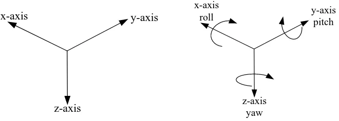
Figure 3-1 The three translational movements and the three rotational motions .... 36
Figure 3-2 Reference Geometry ... 37
Figure 3-3 Airfoil Cross-Section ... 37
Figure 3-4 Aircraft control surfaces ... 38
IX
Figure 3-6 Euler angles ... 42
Figure 3-7 Axis Systems Euler Transformations ... 43
Figure 3-8 Angle of Attack and Angle of Sideslip ... 47
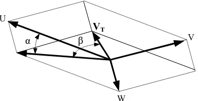
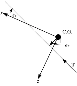
Figure 3-9 Thrust Configuration ... 49
Figure 3-10 Phugoid longitudinal oscillation ... 55
Figure 3-11 Short-period longitudinal oscillation ... 55
Figure 3-12 Possible flight paths due to dynamic effects (a) spiral divergence; (b) directional divergence; (c) Dutch roll ... 57
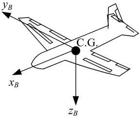
Figure 4-1 X-RAE1 Layout ... 64
Figure 4-2 Pitching moment reference point ... 71
Figure 4-3 nonlinear and linear responses comparsion due to elevator deflection of amplitude 0.005 rad and duration of 1 second ... 81
Figure 4-4 nonlinear and linear responses comparison due to aileron deflection of amplitude 0.005 rad and duration of 1 second ... 82
Figure 4-5 Longitudinal Eigenvalues Plot at Different Velocities... 86
Figure 4-6 Lateral Eigenvalues Plot at Different Velocities ... 87
Figure 5-1 One Degree-of-Freedom Feedback Configuration ... 90
Figure 5-2 Design Trade-Offs for the Multivariable Loop Transfer Function GK (Skogestad and Postlethwaite, 2005) ... 92
Figure 5-3 HMixed Sensitivity Closed-Loop Feedback System with Weights . 100 Figure 5-4 H Loop-Shaping Standard Block Diagram ... 102
Figure 5-5 Scaled and Shaped System Model GS ... 105
Figure 5-6 Controller effect on the open loop system G ... 106
Figure 5-7 Robust controller implementation ... 107
Figure 5-8 LQR Feedback loop... 107
Figure 5-9 H and LQR responses for forward velocity at 30m/s... 108
Figure 5-10 H and LQR responses for downward velocity at 30m/s ... 108
Figure 5-11 H and LQR responses for pitch rate at 30m/s ... 109
Figure 5-12 H and LQR responses for pitch angle at 30m/s ... 109
Figure 5-13 H and LQR responses for height at 30m/s ... 109
X
Figure 5-15 H and LQR responses for throttle at 30m/s ... 110
Figure 5-16 H responses at different velocities for forward velocity ... 111
Figure 5-17 H responses at different velocities for downward velocity ... 111
Figure 5-18 H responses at different velocities for pitch rate... 112
Figure 5-19 H responses at different velocities for pitch angle ... 112
Figure 5-20 H responses at different velocities for height... 112
Figure 5-21 H responses at different velocities for downward elevator ... 113
Figure 5-22 H responses at different velocities for downward throttle ... 113
Figure 5-23 LQR responses at different velocities for forward velocity ... 113
Figure 5-24 LQR responses at different velocities for downward velocity ... 114
Figure 5-25 LQR responses at different velocities for pitch rate ... 114
Figure 5-26 LQR responses at different velocities for pitch angle ... 114
Figure 5-27 LQR responses at different velocities for height ... 115
Figure 5-28 LQR responses at different velocities for elevator ... 115
Figure 5-29 LQR responses at different velocities for throttle ... 115
Figure 6-1 Steps carried out for CFD analysis ... 119
Figure 6-2 3D Geometry of Wortmann FX63-137 ... 120
Figure 6-3 2D mesh of airfoil boundry layer ... 121
Figure 6-4 3D mesh of the Wortmann FX63-137 wing ... 121
Figure 6-5 Comparison of computed lift coefficient and wind tunnel results ... 125
Figure 6-6 Comparison of computed drag coefficient and wind tunnel results .... 125
Figure 6-7 Comparison of computed moments coefficient and wind tunnel results ... 126
Figure 6-8 Flow over upper surface of X-RAE1 wing ... 128
Figure 6-9 Contours of velocity Magnitude of 2D CFD model ... 129
Figure 6-10 Contours of velocity Magnitude and direction of 2D CFD model .... 129
Figure 6-11 Contours of pressure coefficient of 2D CFD model... 130
Figure 6-12 Plot of pressure coefficient of 2D CFD model ... 130
Figure 6-13 Plot of pressure coefficient of 2D CFD model at 14 degrees ... 131
Figure 6-14 Bubble location on airfoil ... 132
XI
Figure 6-16 3D model of airfoil with bubble at trailing edge ... 133
Figure 6-17 3D Comparison of computed lift coefficient between un-modified and modified back bubble ... 135
Figure 6-18 3D Comparison of computed moments coefficient between un-modified and un-modified back bubble ... 135
Figure 6-19 3D Comparison of computed drag coefficient between un-modified and modified back bubble ... 136
Figure 6-20 Contours of velocity magnitude and direction of 3D CFD model .... 137
Figure 6-21 A close-up of the velocity magnitude and direction contours for the 3D CFD model ... 138
Figure 6-22 Contours of pressure coefficient of 3D CFD model... 138
Figure 6-23 Contours of velocity magnitude and direction of 3D modified CFD model ... 139
Figure 6-24 A close-up of the velocity magnitude and direction contours for the 3D modified CFD model ... 139
Figure 6-25 Contours of pressure coefficient of 3D modified CFD model ... 140
Figure 8-1 X-RAE1 longitudinal geometry ((Trebble 1985) ... 147
Figure 8-2 Maximum cross-sectional ... 173
Figure 8-3 Equivalent elliptical ... 173
Figure 8-4 Side elevation area (Sbs ) ... 174
XII
Acknowledgment
Firstly, I owe great thanks to my supervisor, Dr Efstathios Milonidis, for his excellent supervision, guidance and encouragement. I would also like to express my gratitude to my second supervisor, Professor Nicos Karcanias for his constructive feedback. . I am also indebted to Professor George Halikias for his help in the area of control design.
My deepest gratitude to ERSRC for sponsoring me to conduct this research. I would further like to extend my thanks to the School of Engineering and Mathematical Sciences for supporting me during my time at the university.
XIII
Copyright Declaration
The author grants power of discretion to the University Librarian to allow this thesis to be copied in whole or part further reference to him. This permission covers only single copies made for study purposes only, subject to normal conditions of acknowledgement.
XIV
Abstract
The demand for unmanned aerial vehicles (UAVs) has increased dramatically in the last decade from reconnaissance missions to attack roles. As their missions become more complex, advances in endurance and manoeuvrability become crucial. Due to the advances in material fabrication, wing morphing can be seen as an ideal solution for UAVs to provide improvements by overcoming the weight drawback.
This thesis investigates the area of aircraft design and simulation for low speed UAVs looking at performance enhancements techniques for low speed UAVs, and their effects on the aerodynamic capabilities of the wing. The focus is on both suitable control design and wing morphing techniques based on current research findings. The low speed UAV X-RAE1 is used as the test bed for this investigation and is initially analytically presented as three dimensional body where the equations relate to the forces and moments acting on the UAV.
A linearised model for straight flight at different velocities is implemented and validated against a non-linear model. Simulations showed the X-RAE1 to have acceptable stability properties over the design operating range.
Control design techniques, linear quadratic regulators (LQR) and H-infinity optimisation with Loop Shaping Design Procedure (LSDP), are used to design simple control schemes for linearised longitudinal model of the X-RAE1 UAV at different velocities. The effectiveness and limitations of the two design methods show that both designs are very fast, with settling times 2-3 seconds in the height response and remarkably low variation of the results at different velocities.
XV
Symbols and Abbreviations
wing aspect ratio
Vector of unknown parameters wing span drag coefficient lift coefficient D L I A a b C C
C rolling moment coefficient
pitching moment coefficient yawing moment coefficient side force coefficient
mean aerodynamic chord m n y C C C c
D drag
eccentricity force
, , moments of inertia
, , products of inertia
lift, rolling mom
x y z
xy yz zx e
F
I I I
I I I
L ent
tail arm
pitching moment aircraft mass yawing moment , roll rate (body axes) , t I M m N P p
Q q pitch rate (body axes)
, yaw rate (body axes) wing area
tail area thrust
, forward velocity (body axes) t R r S S T U u
, side velocity (body axes) total rectilinear velocity
, downward velocity (body axes)
force (aprat from gravitational) along x T
V v
V
W w
X body axes
, ..., basic aerodynamic derivatives
, ..., normalised aerodynamic derivatives state vector
side force (aprat from gravitational) in bo
o o u X N Xu N x Y dy axes force (aprat from gravitational) along z body axes
XVI
is the set of transfer functions with ( ) principal gain (singular value)
(s), (s) largest and smallest singular values angle of attack
angle of
H G G
s
T
sideslip throttle setting
downwash angle, thrust line orientation, wing twist rudder deflection
eleva
tor deflection
pitch angle taper ration aileron deflection
air density rol
l angle
yaw angle
total angular velocity
3D Three dimensions: x, y and z. 6DOF Six Degrees-of-Freedom dynamics CFD Computational Fluid Dynamics
LSDP Robust Control Loop-Shaping Design Procedure LQG Linear Quadratic Gaussian
1
1
Introduction
Research in aircraft flight and control Engineering is an on-going battle to revolutionise aviation with the aim to reduce emissions and engine noise, enhance passenger safety, aircraft capacity and mobility. The National Aeronautics and Space Administration (NASA) has stated that improvement in aviation is critical to the economic health, national security, and the overall quality of life (Washburn, 2002). This resulted in a multi-disciplinary approach to technology development led by researchers from fluid mechanics/aerodynamics, material science, structural mechanics, and control theory.
This chapter introduces the focus of interest of this research. It presents the area of aircraft design and simulation for low speed UAVs. This compromises of the formation of the six degrees of freedom mathematical model for a low speed UAV. This model describes analytically the motions of the UAV as a three dimensional body where the equations relate to the forces and moments acting on the UAV. This in turn provides the model parameter for aircraft simulation and a basis for the control system design. Control design techniques LQR and H optimisation with Loop Shaping Design Procedure (LSDP) are applied to a UAV and results are presented.
Computational fluid dynamics is then used to investigate and simulate the impact of introducing a smart effector arrays on a UAV. The smart effector array produces a form of active flow control by providing localised flow field changes. These induced changes have direct impact on the aerodynamics forces. The aim, objectives and an overview of the context of each chapter is then provided.
CHAPTER
2
1.1 Background and Motivation
The area of active flow control specialises in developing devices for flight vehicles that affect their flow-field to generate aerodynamic forces. These aerodynamic forces can be used as control forces or used to improve flight efficiency. Current flight vehicles use relatively small number of high authority control surfaces known as rudder, ailerons, elevators and flaps to produce control forces. The advancements in material science has brought forward a new generation of smaller and less specialised distributed devices. These devices can be grouped together in an array and operate in conjunction with the flight vehicles main control surfaces or replacing them altogether. The name given to these devices are Smart Effector Arrays. The smart effector arrays can also be used to increase flight efficiency by producing aerodynamic forces which increase the lift drag ratio, giving the flight vehicle more speed for the same angle of attack. To achieve the required level of flow control a combination of the right smart effector array and placement technique is needed.
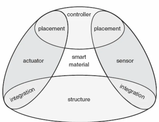
[image:19.595.157.467.497.736.2]The uniqueness of the smart effector comes from its material composition, which is made up of an actuator, sensor and controller all embedded into one structure. An illustrative view of composition of smart effector is given below in Figure 1-1 (Hurlebaus, 2006).
3
The materials used in developing the smart effector are labelled as smart materials, which have interesting and unusual properties. They can "remember" configurations and can conform to them in response to a specific stimulus these being changes in electricity, heat, or magnetic waves. Examples of smart materials are electrostrictive materials, magnetostrictive materials, shape memory alloys, magneto- or electrorheological fluids, polymer gels, and piezoelectric materials.
Once the smart effector array is developed it needs to be incorporated within the flight vehicle control system. This is a challenging task as it requires precise placement and real-time feedback control. The effectors need to be placed where they will have the highest impact on flow control. The control system needs to be aware of which effectors need to be triggered to produce the required response force for a given flight path. Once implemented an intelligent control system can be achieved offering many potential advantages for flight control, including reduced fuel consumption, enhanced maneuverability, robustness and health monitoring. A number of effector arrays and placement techniques have being researched; jets (Sandra, 2007), shape-change blisters (Raney, 2004) and micro flaps (Lee, 2005) showing promising results for the future of aviation.
1.2 Importance of the Research and Potential Outcomes
An unmanned aerial vehicle (UAV) is an aircraft without a human pilot on board. Its flight is either controlled autonomously based on pre-programmed flight plans, or under the remote control of a pilot. UAVs are currently used for a number of missions, including reconnaissance and attack roles. The demand for UAV is growing drastically due to their unique capabilities and advances in manoeuvrability are being sought out. All of which highlights the importance of creating an accurate mathematical model of a UAV to be able to successfully design new innovative ideas.
4
causing wing variations to the overall allowed weight. To address the above challenge, any successful conceptual design for shape morphing of low speed/small aircraft should:
• Undergo large geometry change • Use smart materials for actuation
• Use the smart material actuators for supporting part of the aerodynamic loads • Have integrated and distributed actuators to avoid transmission mechanisms • Use advance light weight composites for the fixed structure and the skin.
The concept of flow control uses smart materials which are made of light weight composites such as shape memory alloys. The key concept of flow control is to affect the flow-field round the UAV which has an impact on the aerodynamics and in turn can be used to reduce drag or produce a control force. The geometry change provided by a single flow control devices is considered small but when combined into an array of devices as a skin round the UAV all working synchronously together they will have a greater effect. The UAV X-RAE1 (Trebble, 1985a) will be used as a test bed for this research due to its classification as a low speed UAV. The X-RAE1 is an experimental UAV with control surfaces and the UAV is powered by a 1.5cc two stroke engine.
The potential outcomes of this research will be the development of a six degrees of freedom mathematical model of an experimental UAV and an analysis of its dynamic responses. The design of a multivariable, robust flight control system and the comparison of selected control techniques. The identification of current state of the art wing morphing techniques capable of improving overall performance for a UAV and carrying out CFD analysis on flow control devices.
1.3 Research Aim, Objectives and Contribution of the Work
1.3.1 Research Aim
5
original X-RAE1 wing from wind tunnel data. The endurance of the wing can be examined across different angles of attack where an increase in endurance can be seen by an increase in lift and a decrease in drag, which subsequently leads to a decrease in drag/lift ratio.
1.3.2 Research Objectives
In addressing the aim, the study has a number of objectives, based on literature analysis and modelling implementation is listed below and illustrated in Figure 1-2 :
To improve and correct an existing nonlinear six degrees of freedom mathematical model of an experimental UAV X-RAE1, which is then linearised for straight level flight.
Design a multivariable, robust flight control system for the X-RAE1 using LQR and H optimisation with loop shaping.
CFD modelling and analysis of the X-RAE1 wing with positioned embedded effector array. Validating and comparing the CFD model to experimental data taken from the original X-RAE1 wing.
6
1.3.3 The Main Contribution of the Work
1. Improvement and correction to an existing six DOF nonlinear model has been undertaken for the X-RAE1 UAV based on a combination of theoretical/ empirical (ESDU datasheets) and experimental wind tunnel data.
2. Validation of the derived nonlinear model via nonlinear/linear simulation studies. Use of preliminary control methodologies, i.e. LQR and H with loop shaping to illustrate that proposed model is fit for control purposes. 3. The use of embedded effector array for active flow control in low speed UAV
through CFD analysis in particular determination of the optimal position of the embedded effector array on the wing.
1.3.4 Dissemination of Results
The main results of this work will be submitted for publication in technical journals and conference proceedings. The first paper is due to be submitted to the conference RED-UAS (Research, Education and Development of Unmanned Aerial Systems) in November 2013. This paper will cover the mathematical modelling and control of the XRAE-1 UAV presented in chapters 4 and 5. The second paper due to be submitted in December 2013 to the Unmanned Systems journal published by world scientific will cover the research carried out on smart effector arrays for low speed UAVs as presented in chapter 6.
1.4 Thesis Structure
The structure of the presented research is based on a framework of theory, modelling and simulation. A brief description of the material covered in each chapter is given below, to provide an overview of the approach followed in this thesis:
1.4.1 Chapter 2: Literature Review
X-7
RAE1 UAV. It commences by briefly discussing the need for shape morphing and the advances in shape morphing materials. The chapter then provides a breakdown of wing morphing variations and current research in each area highlighting the advantages and drawbacks of these implementations in respect to low speed UAVs. Subsequently, flow control techniques are investigated further as a viable solution for the low speed UAVs due to the performance capabilities and positive integration.
1.4.2 Chapter 3: Aircraft Mechanics Review
This Chapter gives an overview of the fundamental areas of aircraft mechanics which will be used in the derivation of the mathematical model and simulation. This encapsulates the breakdown of aircraft motion into pitch, roll and yaw. The non-dimensional reference parameters of the aircraft geometry and the control surfaces in addition to the three axis systems and their translation between each other. This is followed by a brief presentation of the derivation of the equations of motion and their linearisation which is to be implemented for the X-RAE1 UAV.
1.4.3 Chapter 4: The Mathematical Modelling of the X-RAE1 UAV
The concepts and principles presented in chapter three are used in the development of the six degrees of freedom model for the X-RAE1. A combination of static wind-tunnel tests and ESDU data sheets is used for the formulation of the aerodynamic characteristics of the UAV. A linear and a non-linear model is then presented followed by the dynamics for straight level flight for the X-RAE1.
1.4.4 Chapter 5: Control System Design
8
1.4.5 Chapter 6: Effector Array CFD Model
This chapter provides an outline of the Computational Fluid Dynamics Procedure used to construct both a two and three dimensional models of the X-RAE1 unmanned aircraft wing. The first model is a reconstruction of the actual wing which is a Wortmann FX63-137 wing which has a concave lower surface and is used to validate the CFD results against experimental data. The second model is the modified Wortmann FX63-137 with an embedded effector array to modify the air flow. The effect of having an effector array is analysed for lift, drag and moments. Contours around the wing are examined to facilitate the results obtained.
1.4.6 Chapter 7: Conclusions and Recommendations for Future Work
This chapter provides a summary of the research, and presents the main contributions to the field of aeronautics followed by an outline of potential areas of further research.
1.4.7 Appendices: Derivation of the Aerodynamic Derivatives
9
2
Literature Review
This chapter provides a detailed critical analysis of the current state of the art research in wing morphing technologies that can be applied to low speed UAVs such as the X-RAE1 UAV. It commences by briefly discussing the need for shape morphing and the advances in shape morphing materials. The chapter then provides a breakdown of wing morphing variations and current research in each area highlighting the advantages and drawbacks of these implementations in respect to low speed UAVs. Subsequently, flow control techniques are investigated further as a viable solution for the X-RAE1 due to their performance capabilities and suitability.
2.1 Shape Morphing Materials
Inthefieldofaeronautics,“shapemorphing”hasbeenusedtoidentifythoseaircraft that can undergo certain geometrical changes to enhance or adapt to their mission profiles. Current interest in morphing has been fuelled by advances in smart materials. These advances have led to series of breakthroughs in a wide variety of disciplines which have the potential to produce large improvements in aircraft flight (Valasek, 2012). There is no exact definition or an agreement between the researchers about the type or the extent of the geometrical changes necessary to qualify an aircraft for the term “shape morphing” technology. However, there is a general agreement that the conventional hinged control surfaces or high lift devices, such as flaps or slats that provide discrete geometry changes cannot be considered as “morphing” (Sofla et al., 2010).
2
10
The interest of wing morphing lies in the benefits that can be achieved which can be defined as four applications (Friswell and Inman, 2006):
1. Improvement of the aircraft performance to expand its flight envelope
2. Replacement of conventional control surfaces for flight control to improve the performance and stealth characteristics
3. Reduction of the drag to improve the range 4. Reduction of the vibration or the control of flutter
These benefits are achievable due to the advances in material technology being used to produce shape morphing. A recent example is wing morphing for solar powered high altitude aircraft which can fold in such a way to orient a solar panel to be hit more directly by the sun‟s rays at specific times of the day (Dewey and Pezhman, 2013). These Advances have enabled the development of devices which can serve as both sensors and actuators. Integrating these devices into a structure together with a controller, enables the material to become“Smart”.Incorporating actuators within a composite structure to make the structure bend enables the concept of shape control or morphing to be implemented. A smart structure should possess the ability to sense its internal and external environment. It should then be able to communicate the sensory signals via appropriate pathways to one or several signal processing and control modules, where the information is analysed and appropriate actions are decided. If necessary, the decisions must be conveyed to actuators incorporated within the structure, which respond by altering its characteristics such as the shape, size, stiffness, position, or natural frequency (Uttamchandani, 1994).
11 It is common to classify smart materials as:
(a) Intrinsically adaptive materials: This category includes Shape Memory Alloys (SMA) and Shape Memory Polymers (SMP). When stimulated, these materials are subjected to transformations in their molecular or microscopic structures. These transformations induce changes in material mechanical properties. SMAs and SMPs can undergo large free strains and exhibit large blocking forces. Nevertheless, they have a slow response and a limited efficiency.
(b) Active materials: This class includes electro-active polymers (EAP), piezoelectric ceramics (PZT), and magnetostrictive materials. They act as transducers converting electrical, magnetic, or thermal energy into a mechanical energy. Piezo-ceramics exhibit a much lower free strain but they are capable of producing quite high blocking forces, and sensibly more efficient
The material choice depends on the specific morphing purpose. If the morphing is dedicated to flight control, the morphing system should exhibit (Fontanazza et al., 2006):
1. Relatively fast dynamic,
2. Capability to operate over a wide range of flight conditions, 3. High reliability,
4. Capability of repetitive actuation,
5. Robustness against uncertainties and disturbances such as gust loads, 6. Low power consumption.
12
2.2 Shape Morphing Variations
Significant geometric variations of an aircraft wing during flight can allow efficient performance during different flight regimes, or permit multi-role missions that are impossible without the aircraft reconfiguration. Conventional aircraft use mechanisms to change discretely the wing area in different flight configurations. These configurations include take off, climb, cruise and landing. The discrete shape change is achieved by extending or retracting flaps, slats, tabs, ailerons to either modify the wing area and the airfoil camber for additional lift or the aircraft controllability characteristics.
Several methods exist to increase the efficiency of different flight aspects of an aircraft through changing the aerodynamic characteristics of the wing. Changing the span or the aspect ratio of the aircraft wing alters the aircraft lift characteristics, and stealth characteristics for military aircraft. Loitering can be performed more efficiently by changing the airfoil shape through drooping the wings, increasing the airfoil camber, or twisting the wing. Performing any of these changes by morphing during a mission would give increased efficiency in the loiter stage (Cesnik et al., 2004). Table 2.1 defines the aerodynamic advantages of varying the wing geometry.
Max Speed
Range Landing Distance
Take-Off Distance
Manoeuvr-ability
State Change Effectiveness
Relative Total
Span 5 4 4 4 3 4 24
Aspect Ratio 3 4 3 3 2 3 18
Sweep 5 5 5 5 4 4 26
Taper Ratio 1 2 1 1 1 1 7
Thickness / Chord Ratio
1 2 1 1 1 1 7
Camber 2 2 5 5 5 4 23
Table 2-1 Effects of the change type on the aerodynamic characteristics in the scale 1-5 (Cesnik
et al., 2004)
13
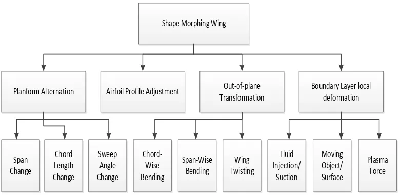
Adapting (Sofla et al., 2010) model of wing morphing classification to include boundary layer local deformations for flow control and by reviewing morphing concepts presented in (Barbarino et al., 2011, Gomez and Garcia, 2011) the wing morphing concepts can be classified into four major types planform alternation, airfoil adjustment, out of plane transformation and boundary layer local deformations. This is presented below in Figure 2-1.
Airfoil Profile Adjustment Out-of-plane Transformation
Boundary Layer local deformation
Chord Length Change
Sweep Angle Change
Chord-Wise Bending
Span-Wise Bending
Wing Twisting
Fluid Injection/
Suction
Moving Object/ Surface Span
Change
Plasma Force Shape Morphing Wing
[image:30.595.124.514.236.426.2]Planform Alternation
Figure 2-1 Classification for shape morphing of wing
The planform alternation is performed through the wing area resizing by changing parameters including the span, chord length and sweep angle. The airfoil adjustment regroups designs that can alter the wing profile with no significant change in the wing camber; the wing thickness control comes under this category. The out-of-plane transformations include the wing twist, the chord and span-wise camber changes. Boundary layer Local deformations includes flutter control devices and flow control devices.
14
boundary layer suction/blowing, synthetic jets, elastic membranes and plasma actuators. Preference is given to the designs that consist of smart materials such as shape memory alloy actuators (SMA), piezoelectric actuators (PZT) or shape memory polymers (SMP).
2.3 Wing Planform Alternations
The wing planform alternation is either singularly or a combination of alterations to the span, chord length or sweep angle at various flight conditions.
2.3.1 Wing Span Morphing
The main advancements in wing span morphing have been by designing telescopic structures. The underlying design in a telescopic wing is several segments with reducing cross sectional area, such that each segment can encapsulate the adjacent inner segment. Depending on the length required for the wing the number of segments can be determined.
15
Figure 2-2 GeversAircraft’sTelescopicWing (Gevers, 1997)
Pines (2003) and Blondeu (2004) designed and fabricated a three segmented telescopic wing with inflatable actuators replacing the traditional spars. These pneumatic spars consisted of three concentric cylindrical aluminium tubes that could achieve variation span configurations. The alignment of the sliding tubes was ensured using ceramic linear bearings. Their full scale telescopic spar could be smoothly deployed and retracted using input pressures of 340-480 kPa. The wing achieved a change of 114% of the wing aspect ratio. Experimentally it was shown that the drag to lift ratio of the fully extended telescopic wing was about 25% lower that it‟s rigid fixed wing. Figure 2-3 presents the design drawings. The telescopic wing is represented in three different stages of extension, with and without the skin.
Figure 2-3 Conceptual Drawings of the Pneumatic Telescopic Wing (Blondeau, 2004, Pines,
2003)
[image:32.595.193.473.497.662.2]16
were carried out however wind tunnel data were inconclusive due to a fabrication malfunction.
For low speed UAVs the advantages of the wings span increasing gives a dramatic improvement in the performance capabilities of the UAV; for example improvement of the rate of climb, range and endurance of the UAV. Nevertheless, the challenges faced by implementing wing span include the ability of the structure to resist bending under the loading due to large wing deflections, a weight penalty, actuator issues, and the energy required to drive the system. Due to an increase in the parasitic drag the telescoping wings have a lower aerodynamic efficiency (lift to drag ratio) than rigid fixed-wings (Pines, 2003).
2.3.2 Chord Length Change
The chord length of the wing in conventional aircraft is resized by means of leading or trailing edge flaps, which are usually moved by actuation systems. Many of these devices are patented and operational. Very few researchers exploited the resizing of the chord length without using such flaps or slats. An early example of chord extension is the flower flap (Day, 2011) used on fixed wing aircraft as illustrated in Figure 2-4. The flower flap slides back from the wing and rotate down creating a slot between it and the wing. The flap acts to increase the wing area and provide additional lift to the aircraft in comparison to traditional flap.
Figure 2-4 Illustration of a flower flap
17
screw mechanism under transverse aerodynamic loads is questionable. In addition, maintaining the chord-wise bending stiffness of the wing remained a challenge. The added weight and complexity of the design are other downsides of this work.
The application of smart materials, on the other hand, to achieve chord change is one of the least studied methods of wing morphing. One attempt is the work of researchers at cornerstone research group who experimented with dynamic modulus foam (DMF) to alter the chord length of wing (Perkins et al., 2004). The DMF foam is a lightweight form of shape memory polymer (SMP) with similar behaviour. The foam is highly stretchable at temperature above the glass transition temperature. Although their prototype wing section was extended along the chord upon heating it could not return to the original shape upon cooling, demonstrating the small recovery stress of shape memory foams. (Johnson, 2010) proposed a concept that composed of a lightweight bistable arch, SMA wires for actuation, a thin plate and support roller for the plate. This concept is expected to add little weight, but further no prototype was created. Further examination of smart materials to alter the wing chord length is an attractive research topic considering the importance of chord length of the aerodynamic behaviour of the wing, especially the induced drag.
2.3.3 Sweep Angle Variation
The concept of sweep change has been implemented in many successful and operational aircraft such as Bell X-5, F14 (Weisshaar, 2006). The method used to accomplish wing sweep is a complex pivoting mechanism on the wing. The wing sweep change is designed to change the wing configurations to suit the various flight conditions (Ma et al., 2004). For supersonic flight the Bell X-5 has small compact wings for high speed flights and one with larger area and span for take-off climb and cruising.
18
internal components that create wing area and span changes, including changing leading edge sweep to control aerodynamic drag. The variable geometry wing has the ability to move between five different wing planforms as illustrated Figure 2-5. The design incorporates wing planform changes in area, span, chord, and sweep that vary by 51%, 36%, 110% and 30 degrees, respectively (Weisshaar, 2006).
Figure 2-5 Morphing wing configurations for high-lift (Weisshaar, 2006)
On the other hand Mattioni (2008) successfully demonstrated the use of unsymmetrical laminated composites to realise a variable sweep wing for morphing UAV applications. Their numeric analysis identified the bifurcation point referred to as a snapping point at which the geometry changes. This confirms the possibility of eliminating mechanical joints to obtain different geometries. In their design, the wing spars are made of bi-stable composites. When a bending moment is applied on the spar, it causes the spar to snap to a second stable position around the bifurcation point which acts as a hinge. Therefore, the application of multistable composites simplify the complex mechanical systems required to modify the geometry of conventional wings (Friswell, 2011). However, the use of bi-stable composite materials may suffer from fatigue at the bifurcation point. Furthermore, the compliance of the wing skin may interfere with the snapping motion.
An increase of the sweep angle improves the aerodynamic performance at high speed regimes. Additionally, it significantly increases the flight envelope of an aircraft
Wing design L/D ratio 1.00
bdash/2 = 7.2 ft. Sdash= 23.9 sq.
ft. Wing design
L/D ratio 1.60 b/2 =9.8 ft. S =17.4 sq.ft.
.Wing design L/D ratio 1.23 b/2=7.2 ft. S = 15.8 sq. ft.
.Wing design L/D ratio 1.39
b/2 = 9.8 ft. S = 22.8 sq. ft. Wing design
L/D ratio 1.45 b/2 = 8.8 ft. S = 17.0sq. Ft.
Dash/Maneuver (baseline) Loiter Cruise Climb High Lift Wing design L/D ratio 1.00
bdash/2 = 7.2 ft. Sdash= 23.9 sq.
ft. Wing design
L/D ratio 1.60 b/2 =9.8 ft. S =17.4 sq.ft.
.Wing design L/D ratio 1.23 b/2=7.2 ft. S = 15.8 sq. ft.
.Wing design L/D ratio 1.39
b/2 = 9.8 ft. S = 22.8 sq. ft. Wing design
L/D ratio 1.45 b/2 = 8.8 ft. S = 17.0sq. Ft.
Dash/Maneuver (baseline) Loiter Cruise Climb High Lift
19
originally designed for low speed flights. However it can be seen that the structural morphing is complex and made from heavy mechanisms composed of pivots. These pivots must bear bending and torsion loads; they tend to be heavy due to their thickness, reducing thus the overall effectiveness of the design especially when considering them for low speed flight. It is clear that several improvements are needed to reduce these disadvantages.
2.4 Out-Of-Plane Transformations
An alternative approach to modifying the aerodynamic characteristics of a wing is to alter the wing out of its original plane. Several researches have shown the potential of smart materials to accomplish the out-of-plane alternation of a morphing wing through camber change. This section presents the wing camber, chord, and twist controls.
2.4.1 Chord Wise Bending
20
moments applied alternatively by actuators on the edges of the laminate. Thus, the chord-wise composite member controlled the airfoil camber, while the vertical element altered its chord length.
Furthermore, (Narcis et al., 2006) demonstrated that by using structures that are acting in the post-buckling regime, it is possible to obtain significant changes in shape with very modest changes in the applied load. Thus, by making use of non-linear structural responses, camber control of deformable airfoils can be achieved by using a carefully designed pre-loaded internal spinal structure. Such a structure is expected to move through the desired shape changes under the control of a single actuator. This actuator will deliver aerodynamic characteristics that match a set of pre-specified target shapes and also give improved aero-elastic properties.
(Sofla et al., 2004) developed a series of SMA-actuated flexural structures which could be used to deform wing sections. Their actuated structures were based on a concept called Antagonistic Flexural unit Cell (AFC). In this concept, a pair of one-way SMA actuators is placed at either side of a highly flexible unit core structure with large in-plane stiffness. The contraction of one SMA actuator upon heating results in the extension of the opposing SMA actuator mechanically. The contraction by heating of the now-extended actuator, later in the cycle, reverses the actuation.
21
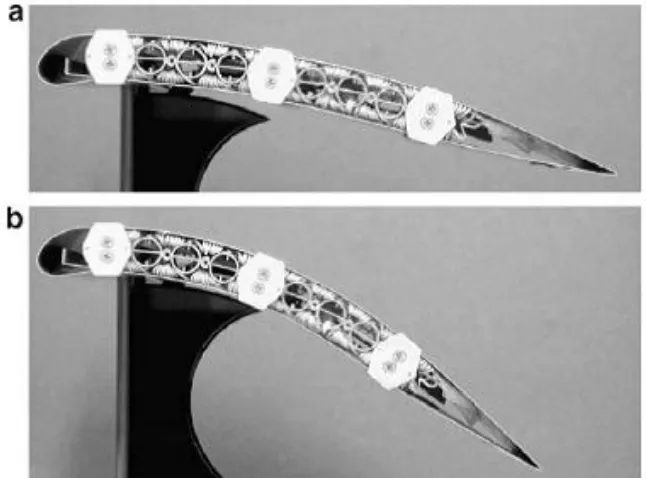
Figure 2-6 illustrates a wing section prototype that is capable of undergoing camber changes when actuated by antagonistic SMA actuators.
Figure 2-6 Chord-wise bending achieved by the heating of SMA strips in an antagonistic design.
(a) Un-morphed and (b) morphed (Elzey DM 2003)
The development of smart materials has become the main focus of variable camber wing actuation technology today. Piezoelectric materials and Shape Memory Alloys have shown some possibilities to be used as actuators for deforming the wing profile.
2.4.2 Span Wise Bending
22
the form of actuators displacement, the rest of the segments could adapt to the desired positions. Manzo and Garcia also investigated the shape morphing of HECS wing by using SMA tendons and DC actuators through a finger like approach(Manzo, 2006). They constructed a wing that could mimic an HECS profile by dividing the wing to five segments along the span. The main problem associated with their design was that the SMA had to be kept heated in order to carry aerodynamic loads.
2.4.3 Wing Twist Control
Morphing via variable twist, the wing is configured to optimise the twist angle to obtain low drag and high lift aerodynamic characteristics. Sofla et al (Sofla et al., 2009) reported that the gradual changes of the airfoil camber along the span can create a controllable twisting of the wing. In their design, an antagonistic wing was prototyped using shape memory alloy (SMA) actuators. An antagonistic structure is based on a pair of one-way SMA actuators as described under the chord wise bending section. Thus, the wing undergoes twisting by the asymmetric actuation of its SMA actuators.
23
Figure 2-7 presents the twisting of a wing section using antagonistic SMA actuation (Elzey et al.,
2003)
In Figure 2-7, twisting of a wing section achieved by antagonistic SMA actuation. (a) The left rib is flexed downward and right rib upward. (b) The left rib is actuated upward and the right one downward (Elzey et al., 2003).
Figure 2-8 illustrates the nominal wing and the morphed wing when each servo-motor is commanded to its equal but opposite value (Abdulrahim et al., 2005).
Figure 2-8 Nominal wing (left) and morphed wing (right) (Abdulrahim et al., 2005)
Moreover, adaptive aero-elastic structures offer potential solutions to achieve wing morphing through out-of-plane transformation. This approach uses the aerodynamic forces acting upon the wing to provide the necessary forces and moments to bend and twist the wing.
2.5 Airfoil Profile Adjustments
24
optimum airfoil configuration. Thus, if an airfoil section can be changed accordingly with the change in flight conditions, benefits may result that include the improvements of the Mach number, aerodynamic efficiency, aerodynamic performances such as the range, endurance, and the expansion of the flight envelope. Austin et al (Austin et al., 1994) developed a theoretical method which was experimentally validated. Their purpose was to control the static shape of flexible structures by employing internal translational actuators. In their design, 14 linear actuators were attached diagonally to form a wing rib structure. The diagonal elements are translational actuators that expand and contract to deform the airfoil. A prototype of the adaptive rib with the actuators was constructed to demonstrate the shape- control concept.
Figure 2-9 Airfoil profile control (Austin et al., 1994)
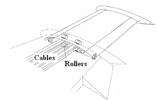
(Dong et al., 2008) designed and manufactured a changeable airfoil model using SMA springs between the wing skin and its supporting wing-box. Therefore, by changing the constraint condition of the skins, they can achieve large deformation without over- stepping their strain allowance. Shape memory alloy springs with the help of stop structures were used to actuate accurately certain points on the skins to approach the target airfoil. The wing-box consisted of rigid steel ribs and spars. The covering skin was allowed to slide over a cushion at the leading edge spar as illustrated by Figure 2-9. Cushions were used in order to avoid dislocation between the skins which were level with that of the tailing edge box. The resizing of the SMA spring length upon heating and cooling could alter the wing thickness.
2.6 Boundary Layer Local Deformation: Active Flow Control
25
dramatically improve system performance using effective control strategies. However, the number of instances in which flow control has successfully transitioned from a prototype to a real-world aeronautical application is small (e.g., (Pugliese and Englar, 1979, Nagib et al., 2004, Shaw et al., 2006)).
The aerodynamic characteristics of low Reynolds number flows are typically vastly different than those normally seen in typical aerodynamic and aerospace applications. Slight changes in the flow speed can have large effects on the flow over a given airfoil, most notably severe changes in lift to drag ratio. An improvement of the lift to drag ratio can greatly benefit UAVs (Santhanakrishnan et al., 2005).
The key concept of boundary layer flow control is avoiding flow separation which affects the lift and drag. Figure 2-9 (English et al., 2010) is a schematic diagram of the aerodynamic flow control using fluidic actuators. The upper figure shows flow separation and loss of lift at a high angle attack. While the bottom figure shows apparent surface modification of the flow leading to flow reattachment and recovery of lift.
Figure 2-10 Flow separation modification (English et al., 2010)
26
A later development in engineering research and development is active flow control devices. These devices have the unique ability to operate in a range of conditions and when needed to improve flow characteristics. Some examples of these devices are trailing edge flaps, blown flaps, suction or blowing through orifices, thermal riblets, synthetic jets, electrostatic and plasma interactions with flows, acoustic cavities or forcing, surface deformation, and rapid transverse strain (Joslin and Miller, 2009).
2.6.1 Fluid Injection/Suction
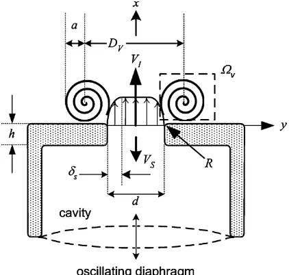
Synthetic jet actuators (SJAs) have emerged as an adaptable actuator for active flow control having a great potential of active control of boundary layer separation in order to reduce the drag and increase the efficiency of aerodynamic devices (Amitay et al., 2001, Gilarranz et al., 2005a, Gilarranz et al., 2005b, Glezer and Amitay, 2002). Using SJAs to control flow separation was considered as the enabling means for the next-generation of UAVs and advance air mobility systems (Pilon, 2004). Most recently wind tunnel tests have been carried out on a hump with embedded synthetic jets showing a positive effect on the decrease of the loss coefficient in the region of the measured velocities, especially at the lower velocities (Pick et al., 2013).
27
The use of synthetic jets to control flow separation in a boundary layer is based on the idea of accelerating the transition from laminar to turbulence which is more capable of resisting laminar separation. In the most recent publication, Gilarranz et al reported their work on developing a high-power synthetic jet actuator which acted as a reciprocating air compressor with a crank system and six pistons (Gilarranz et al., 2005a). The maximum power consumption of this synthetic jet actuator was 1200W and the peak jet velocity was 124 m/s. They also reported the application of this newly developed synthetic jet actuator to flow separation control over a NACA 0015 wing in conditions with a free stream velocity of 35m/s and a Reynolds number of 8.96x10⁵. Their results showed that the synthetic jet actuation successfully decreased the drag and increased the maximum lift coefficient by 80% when the angle of attack was varied from 12 to 18 degree (Gilarranz et al., 2005b). Georgia Tech demonstrated the success of synthetic jet actuators for flow separation control on a low speed, 50 degree swept wing UAV (Parekh et al., 2003, Washburn and Amitay, 2004). By applying separation control to one or the other wing, significant roll moments were achieved at angles of attack above 15 degrees. Researchers at University of Bath in the United Kingdom have looked into using synthetic jets for propulsion and enhanced aerodynamics of Micro Air Vehicles (Whitehead J., 2003).
[image:44.595.188.399.41.242.2]Electrodynamic synthetic jets are attractive for low-frequency applications because of their large displacement capability, but their increased weight (due to the magnet
28
assembly) and heat transfer (due to heating in the resistive coil) present design challenges (Nagib et al., 2004, McCormick, 2000, Agashe et al., 2009).
2.6.2 Moving Object/Surface
Moving surface actuators can take various forms, but the most common are the piezoelectriccompositeflaps,electroactivedimplesandballoon actuators. These are summarised below.
The piezoelectric flap actuator has been used successfully in a variety of applications, including control of separation (Seifert et al., 1998), turbulent boundary layer streaks (Jacobson and Reynolds, 1998, Jeon and Blackwelder, 2000) flow-induced cavity oscillations (Raman G, 2002, Kegerise et al., 2007a, Kegerise et al., 2007b). A cantilever composite beam configuration is commonly used. The actuator can introduce spanwise or streamwise vertical perturbations into the flow depending on the geometry and orientation of the vibrating tip with respect to the local free-stream flow (Cattafesta and Sheplak, 2011). Application of an ac voltage across the piezoceramic causes the beam to vibrate, which then interacts with the flow as illustrated in Figure 2-12. Composite beam modelling is treated in (Cattafesta et al., 2001) and an extension to a bimorph is presented in (Mathew et al., 2006).
Figure 2-12 Sample applications of piezoelectric flap actuators (Cattafesta and Sheplak, 2011)
29
mechanical pressure is produced. The induced strain in the thickness direction produces lateral expansion. The lateral strain is constrained at the boundary, which leads to out-of-plane buckling. The dimples thus produce unsteady surface depressions that interact with the near-wall turbulent structures.
Electrostatic Pressure
Expansion Force Reaction Force
Deflection
Figure 2-13 Principle operation of a dimple
Research is focusing on understanding and predicting the behaviour of the micro fabricated dimples and ultimately designing devices with the desired size, gain, and bandwidth requirements (Dearing et al., 2007).
(Raney et al., 2004, Raney et al., 2000) examined the use of distributed shape-change effector arrays for flight control on a UAV. The distributed shape-change effector arrays were modelled as a series of bumps normal to the aircraft surface which could be deployed to generate control moments as illustrated in Figure 2-14.
Figure 2-14 Shape-change device modelled as deflection of grid point along normal vector
30
Analysis was done to find the favourable locations for the placement of the shape-change device arrays on UAV. Each morphing device was in an array which were either completely on or off. To produce a larger force as required the devices are turned on. The simulation results indicate that the effector suite possessed sufficient authority to stabilise and manoeuvre the example vehicle model, executing relatively low-rate rolling manoeuvres at 10 degrees per second. When substantial atmospheric disturbances were included in the simulation the device arrays did not possess sufficient authority to maintain stability of the vehicle's lateral directional.
A new type of flexible balloon actuator for active flow control has been developed with structural flexibility and perfect air-tightness even with internal high pressure gas. The balloon actuator inflates a spine-on elastic membrane by using an external gas flow as show in Figure 2-15 (Lv et al., 2012). When the balloon actuator is at rest, the top surface of the actuator matches with the surface of the airfoil. When the balloon actuator is actuated, the elastic membrane is inflated, thereby creating asymmetry on the aerodynamic body, resulting in control of the flow.
Figure 2-15 Structure of a balloon actuator (Lv et al., 2012)
31
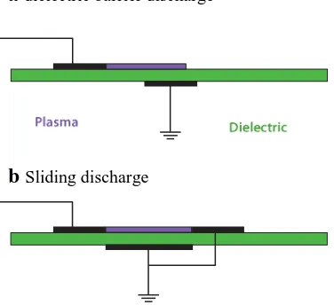
2.6.3 Plasma
Plasma actuators are becoming increasingly popular because they have no moving parts and have rapid time response and low mass. A recent extensive review on plasma devices and their applications have been carried out (Corke et al., 2007, Corke et al., 2010, Moreau, 2007). Followed by a comprehensive discussion on their efficiency and performance (Kriegseis et al., 2012).
adielectric barrier discharge
[image:48.595.217.405.226.398.2]bSliding discharge
Figure 2-16 Schematics of two common plasma actuators: (a) dielectric barrier discharge
(DBD), and (b) sliding discharge (Cattafesta and Sheplak, 2011)