Inversion-symmetry breaking in spin patterns by a weak magnetic field
I. Kreši´c,1,2,3,*G. R. M. Robb,1G. Labeyrie,4R. Kaiser,4and T. Ackemann1
1SUPA and Department of Physics, University of Strathclyde, 107 Rottenrow East, Glasgow G4 0NG, United Kingdom 2Institute of Physics, Bijeniˇcka cesta 46, 10000 Zagreb, Croatia
3Institute of Theoretical Physics, Vienna University of Technology, Vienna A-1040, Austria
4Université Côte d’Azur, CNRS, Institut de Physique de Nice, 06560 Valbonne, France
(Received 26 February 2019; published 30 May 2019)
Laser-driven cold atoms near a plane retroreflecting mirror exhibit self-organization above a pump threshold. We analyze the properties of self-organized spin patterns in the ground state of cold rubidium atoms. Antiferromagnetic patterns in zero magnetic field give way to ferrimagnetic patterns if a small longitudinal field is applied. We demonstrate how the experimental system can be modeled as spin-1 atoms diffractively coupled by the light reflected by the mirror. The roles of both dipolar and quadrupolar magnetization components in determining the threshold and symmetry variations with a weak longitudinal magnetic field are examined. Although the magnetic structures correspond dominantly to a lattice of magnetic dipoles, the symmetry breaking to ferrimagnetic structures in a finite field is mediated by the coupling to a homogenous quadrupole (alignment), which is not possible in a spin-1/2 system. Our study provides a basis for further exploration of instabilities in driven multilevel systems with feedback.
DOI:10.1103/PhysRevA.99.053851
I. INTRODUCTION
Light-mediated cold-atom self-organization is an emerging research avenue with potential applications in metrology and condensed matter simulation [1–19]. In this paper, we study the phenomenon of self-organization arising in an optically nonlinear sample due to diffractive coupling via single mirror feedback [20,21]. While initial observations of these struc-tures were performed in liquid crystals and warm atomic vapors [22,23], the scheme was recently extended to thermal cold gases, where the nonlinearity can be of optomechanical, electronic saturable, or magnetic origin, with corresponding structuring of atomic density, optical coherence, and mag-netization, respectively [5,6,24–26]. These systems are in-teresting as they have a single pump axis and hence allow for spontaneous symmetry breaking of the translational and rotational degrees of freedom in the plane transverse to this axis, whereas in systems with multiple distinguished axes (e.g., a cavity axis and a pump axis), the potential symmetries and realizations are constrained.
As in Refs. [25,26], in this article the relevant degrees of freedom are populations and coherences in the ground-state Zeeman sublevels and the optical nonlinearity is provided by optical pumping, i.e., is magnetic optical in origin. The result-ing instability creates both transverse spatial modulations of the atomic spins and the polarization profile of the laser beam. The magnetic phase space of the instabilities was explored in Ref. [26]. In zero magnetic field, complementary intensity patterns with square symmetry are found in theσ± compo-nents of the transmitted beam. These are optical spin patterns arising from spontaneous symmetry breaking of the zero net
optical spin state in the linearly polarized pump field. The optical patterns indicate the spontaneous emergence of a spin pattern in the atoms, i.e., a spontaneous magnetic ordering of dipoles, in this case antiferromagnetic. In Ref. [25], an analogy was established between this system and the Ising model. Diffractive ripples in the feedback field caused by a local perturbation of the atomic magnetization lead to optical pumping in the same direction one lattice period away and opposite direction half a lattice period away, leading to the antiferromagnetic coupling. If the up-down symmetry is bro-ken by a small longitudinal field, the antiferromagnetic spin phase gives way to ferrimagnetic phases with hexagonal order. These became more irregular at higher absolute values of the magnetic field. In Refs. [25,26], it was hypothesized that the symmetry breaking at large|Bz|is due to the linear and the
incoherent nonlinear Faraday effect, but that at small|Bz|the
coupling of the dipole states to higher multipoles via coherent effects is important. In this article, we provide a systematic study of the variation of pattern properties with the longitu-dinal magnetic field Bz, outlined in Ref. [25]. The threshold
and symmetry properties are studied both experimentally and theoretically, with one of the main goals being the elucidation of the pattern selection and symmetry-breaking mechanism.
Bzand how this is amended by using instead the optical Bloch
equations, including both populations and coherences in the ground states of a spin-1 model. We calculate analytically the expressions for the threshold and the pattern symmetry parameter at a givenBz, by using the experimentally motivated
approximation that the instability is driven by optical pumping of atomic spins due to an intensity difference in the two σ components of the feedback field. Moreover, another result of this analysis is the discovery that the inversion, i.e., up-down, symmetry of the system is broken at small |Bz| by a
coherent nonlinear Faraday effect, governed by light-induced |m| =2 ground-state coherences [36]. We demonstrate that the threshold dynamics of the spin perturbation amplitudes in the simplified model is determined by a set of complex Ginzburg-Landau equations [37], describing wave mixing of spin modes on a Talbot circle. The symmetry breaking is pro-vided in these equations by a term quadratic in the spin modes.
II. EXPERIMENTAL SETUP
Most of the experimental data presented in this paper were obtained with a setup located at the University of Strathclyde. A cloud ofN=9×10⁸ 87Rb atoms atT =125μK is loaded into a magneto-optical trap (MOT), which is then released by turning off the cooling laser beams and the gradient magnetic field, after which an external homogeneous magnetic field is applied to facilitate the study of pattern properties. After a waiting time of 3.5 ms needed for stray magnetic fields to decay, a cloud with on-resonance optical thickness of about
b0=27 and FWHM≈3 mm is prepared for pattern formation experiments. A linearly polarized pump beam with a FWHM of 0.8 mm, intensities in the rangeI =1−30 mW/cm2, and a typical detuning of = −71= −142, where1 is the population and2is the optical coherence decay rate, is then turned on to irradiate the center of the cloud for a typical duration oft =250μs. This pattern-inducing pump beam is retroreflected from a feedback mirror with reflectivityR=
0.95. The mirror is put (i.e., imaged) at an effective distance
d of a few millimeters from the center of the cloud by using a pair of lenses with focal lengths f =12.5 cm placed between
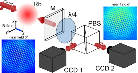
the cloud and mirror in the 4f configuration [38]. The small part of the light transmitted through the mirror is used for pattern imaging of theσ-polarization components. Both real space or near-field (NF) images of the reentrant beam intensity distributions and Fourier space or far-field (FF) data are used in the results presented in this paper. A simplified schematics of the setup is presented in Fig.1.
Additional observations were done in a setup at the Uni-versité Côte d’Azur, described in Refs. [25,26]. The main difference to the setup described above is that a higher optical density of up to 110 can be obtained.
III. EXPERIMENTAL OBSERVATIONS
A. Pattern symmetries
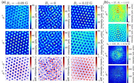
In Fig. 2, we present NF images of experimental real-izations of patterns characteristic for the three ranges of the applied longitudinal magnetic field,Bz. NearBz=0, patterns
with square and rectangular symmetries were observed. In the Strathclyde setup, these patterns contained defects,
deforma-Rb
M
/4
PBS
780 nm
y' z' x'
B-field
[image:2.608.317.557.74.201.2]CCD 1
CCD 2
FIG. 1. Simplified schematics of the experimental setup, adapted from Ref. [25]. A linearly polarized pump beam is reflected from a feedback mirror to drive the spin self-organization in the atomic cloud. A small transmitted part of the beam is used for polarization selective NF and FF (not shown) imaging. Inversion symmetry is broken by applying a small longitudinal magnetic field (B field), resulting in formation of hexagons and honeycombs in theσ po-larization channels (inset: NF data). Rb, cold cloud of 87Rb; M, feedback mirror; λ/4, quarter-wave plate; PBS, polarizing beam-splitter cube; CCD, charge-coupled device camera.
tions, and irregularities of amplitudes [see center column of Fig.2(a)], the analysis of which, although in itself interesting, is beyond the scope of this article. For the Nice setup, a clear long-range order with square symmetry was observed.
Increasing the |Bz| to values larger than ≈0.05 G
(de-pending on pump intensity, see below), the pattern symme-try changes to hexagonal, with σ+ light forming hexagons (honeycombs) andσ−light forming honeycombs (hexagons), for positive (negative) Bz values. The modulation depths of
the channels are now unequal, with positive (negative) σ being more modulated for positive (negative)Bz. For all three
symmetries, the regions of excessσ light are complementary, which leads to the conclusion that the main driver of insta-bility is the intensity difference of theσ components. This is seen in the subtracted NF images shown in the lowest row of Fig.2(a)and will motivate the approximations used in Sec.VI. The inversion symmetry of σ± modulation amplitudes is present within experimental uncertainties for |Bz|<0.05 G
and absent for higher|Bz|. To first order in spin modulation,
the difference in these modulation amplitudes gives an indi-cation of the atomic spin modulation [see Eq. (3) and the corresponding discussion in Sec.Vbelow]. The last row of Fig.2(a) shows antiferromagnetic states around Bz=0 and
ferromagnetic states atBz = −0.09,0.12 G, with the sign of
the dominant magnetization depending on the sign ofBz. The
origin of this symmetry breaking is one of the subjects of this paper. Similar symmetry breaking by an external magnetic field is known to occur in the Ising model [39–42].
The NF images at large positiveBzare shown in Fig.2(b).
FIG. 2. Near-field images of the transmitted part of the reentrant beam intensities (see text) in the self-organized magnetization phases, for varyingBz. (a) Columns (left to right):Bz= −0.09 G,Bz=0,Bz=0.12 G. Rows (top to bottom):σ+,σ−andσ+−σ−(Strathclyde).
The difference images are normalized to their respective maximum absolute values. The situations forBz=0 correspond to ferrimagnetic
spin lattices, whereas the situation forBz=0 corresponds to an antiferromagnetic spin lattice. (b) Top rows:σ+,σ−images forBz =1.4
G (Strathclyde). Bottom rows: σ+, σ− images for Bz=0.54 G (Nice). Experimental parameters (Strathclyde): b0=27, = −142,
I=10 mW/cm2, d= −2.9 mm, R=0.95, field of view 0.36×0.36 mm2. Experimental parameters (Nice): b0=110, = −242, I=22 mW/cm2,d= −20 mm,R=0.99, field of view 3.15×3.15 mm2.
B. Diffracted power
Figure 3 shows scans of diffracted power Pd in the σ
polarization channels against Bz for three values of pump
FIG. 3. Diffracted power at small longitudinal magnetic fields (Strathclyde). (a) I=14 mW/cm2. (b) I=19 mW/cm2. (c) I= 24 mW/cm2. Dots,σ+light; circles,σ−light. Experimental
param-eters:= −142,b0=27,d= −2.9 mm.
beam intensity. ThePd was extracted from the FF data as the
diffracted power in the first Talbot ring, since the power in higher rings was zero at the experimental parameters used [43]. The diffracted power in the two circular polarization channels is approximately equal near zeroBz. When we
in-crease theBzmagnitude above≈0.03 G, the relative diffracted
power in the two channels starts to differ; namely, forBz >0
there is an increase in σ+ and for Bz<0 an increase in
σ− diffracted power. This indicates that theσ+ (σ−) lattice becomes stronger for positive (negative)Bz, which is seen in
NF images of Fig.2(b).
The feature in Bz has a subnatural linewidth; i.e., it is
narrow even if it does not appear to be on the displayed span which corresponds to maximum Larmor frequencies z≈
6×10⁵s−1≈0.03
2. Its width increases with the beam in-tensity, reminiscent of power broadening in the nonlinear Faraday rotation for an F =3→F=4 transition reported in Refs. [36,44]. We have observed this narrow feature in independent measurements of the rotation angle in a single-pass configuration at the same experimental parameters [45]. The total diffracted power has a similar qualitative behavior as the dominant polarization component and is analyzed in the next section.
C. Threshold intensities
[image:3.608.51.293.496.702.2]FIG. 4. Diffracted power and threshold intensity for positive Bz (Strathclyde). (a) Threshold pump intensity. (b) Total diffracted
power for varying input beam intensity. Triangles (black): I = 3.1 mW/cm2. Diamonds (red): I=5.5 mW/cm2. Squares (blue): I =7.1 mW/cm2. Experimental parameters:= −142,b0=27, d=1.3 mm.
shows threshold beam intensityIt h againstBz. The threshold
is minimal in zero field. For smallBz,It hincreases withBzand
peaks at≈0.25 G. On further increasingBz,It hbegins to drop
and levels off to a constant value. It will be shown in Secs.V
andVIthat this dependence onBz can be accounted for in a
theoretical model describing the atoms as a spin-1 medium. Scans of the total diffracted power forBz >0 are shown in
Fig.4(b). Depending on the pump beam intensity with respect to the threshold [see Fig. 4(a)], different behaviors are ob-served. At low beam intensities above threshold, thePd drops
at small Bz and remains zero for higher field magnitudes.
As we increase the beam intensity, the Pd feature inBz gets
broader and exhibits a revival after an initial strong decrease. This is related to the results of Fig. 4(a), as the increase (decrease) of the pattern threshold corresponds to a decrease (increase) of diffracted power at a fixed pump intensity. Input intensities below 4 mW/cm2 are below the minimum threshold for the revival at high-Bz fields and the magnetic
ordering occurs only in the central lobe. The width of the lobe increases with intensity, indicating power broadening of a magneto-optical resonance. The total diffractive power and the dominant polarization component show qualitatively similar behavior.
IV. THEORETICAL MODEL
A. Atom dynamics
We now outline the theoretical model for the internal degrees of freedom of the atomic medium interacting with the pump laser. The large pump beam detuning in our experiments allows for the use of the low saturation approximation, where atom-light interaction is modeled by considering only the ground-state populations and coherences of the density matrix ρ; see, e.g., Refs. [27,35]. In addition to this, for simplicity we also approximate the experimentally excited F =2→F=
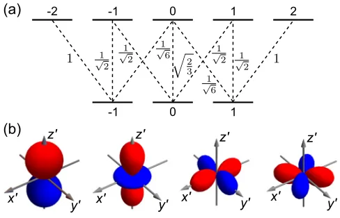
3 transition of the D2 line of87Rb with anF =1→F=2 transition as it contains the relevant multipoles. It should be also noted that the multipoles of rank higher than 2 do not pro-vide a feedback to the light field. Choosing the quantization axis parallel to the pump propagation directionzand setting the transverse magnetic fields to zero, we identify the relevant
FIG. 5. Model atomic system. (a) Zeeman sublevel structure of the F =1→F=2 transition with the corresponding Clebsch-Gordan coefficients. (b) Illustration of symmetries of the tensors related to the magnetic momentsw,x,u,v, from left to right.
atomic variables to beu=2Re(ρ1−1),v=2Im(ρ1−1),w= ρ11−ρ−1−1, andx=ρ11+ρ−1−1−2ρ00 (whereρi,jare the
density matrix elements of theith and jth Zeeman sublevels of the spin-1 ground state), given respectively by the expecta-tion values:F2
x −Fy2,FxFy+FyFx,Fz, and3Fz2−F2,
whereF2 andF
x,y,z are hyperfine angular momentum
opera-tors [46]. Each of the above variables is also proportional to a coefficient of the irreducible tensor expansion of the density matrix, known as a polarization moment, the knowledge of which is sufficient to describe the angular momentum state of an atomic ensemble [46]. The characteristic spatial sym-metry of each tensor is given by the corresponding spherical harmonic function, as shown in Fig. 5. The w variable is also called orientation (spin) and corresponds to a dipole, whereas the alignmentxand coherencesuandvcorrespond to quadrupoles.
Temporal dynamics of the atomic variables is described by a set of optical Bloch equations. After adiabatic elimination of the optical coherences and the excited state variables (up to the order of±/[35], where±are Rabi frequencies of the σ light components), one is left with a set of four equations for the ground-state variables [25,26,45]
˙
u= −cu+
2z+
5 6D¯
v+1
6P−¯w
−1 9P+x+
5 18P+,
˙
v = −cv−
2z+
5 6D¯
u+1
6P+¯w
+1 9P−x−
5 18P−,
˙
w= −ww−
1
6P−¯u− 1
6P+¯v− 1 9Dx+
5 18D,
˙
x= −xx−
1 3P+u+
1 3P−v+
1 3Dw+
5
[image:4.608.311.555.70.227.2]where the pump rates are
S= 1
2
|+|2 1+( ¯−¯z)2
+ |−|2 1+( ¯+¯z)2
,
D= 1
2
|+|2 1+( ¯−¯z)2
− |−|2 1+( ¯+¯z)2
, (2)
P+= 2 2
Re(∗ +−)
1+¯2 , P−= −2 2
Im(∗ +−) 1+¯2 ,
and the decay rates are w=γ +16S, x=γ+
11
18S, andc=γ+ 5
6S. Here, γ is an effective decay rate of the Zeeman ground-state populations and coherences, detuning is normalized as ¯=/2, andz is the Larmor
precession frequency in a longitudinal magnetic field. Rabi frequencies ± are related to the electric fields E± as ±=μdE±/h¯, whereμd is the dipole matrix element of the
stretched state optical transitions. In the following, we use the expression ±=1
√
I±/2Is, withIs=1.669 mW/cm2.
Equations (1) are valid in the case when no transverse magnetic fields are present, and the |m| =1 ground-state coherences vanish. When we neglect the coupling to other multipoles, Eqs. (1) show that the orientation w is driven by an intensity difference in the two circular polarization components, thexvariable is driven by light polarized along any direction, whereasuandv couple most strongly to light polarized alongxoryand at 45◦toxory, respectively. The pumping ofw andx is related to incoherent processes (i.e., insensitive to the phase between theσ+andσ−components), whereasuandvare pumped in a coherent way (i.e., sensitive to the relative light phase of the circular components).
B. Field evolution
We will consider the propagation of the slowly varying electric field envelopes ˜E±=F˜±+B˜±, where ˜F± are the forward- and ˜B± the backward-propagating σ electric field components. In the next two subsections, we normalize the electric fields asE0=0/
2(1+¯2),where0=+= − since we use a beam polarized along the y direction, and we write I0= |E0|2 for the intensity of each circular component.
The pump terms in Eqs. (1) are all quadratic in the op-tical fields and will include terms ≈e±2ikz due to the
in-terference of the counterpropagating beams. As the ground-state dynamics is rather slow, the atoms will traverse several optical wavelengths on the timescale of the state dynam-ics (10μs), and so these grating terms will be averaged out and will not contribute to the response of the atomic variables. We will therefore ignore these “longitudinal grat-ing” terms, replacing the pump terms S, D, P+, and P−
with their spatial averages κ+(|F˜+|2+ |B˜
+|2)+κ−(|F˜−|2+ |B˜−|2),κ+(|F˜
+|2+ |B˜+|2)−κ−(|F˜−|2+ |B˜−|2), 2Re( ˜F+∗F˜−+ ˜
B+∗B˜−), and −2Im( ˜F+∗F˜−+B˜∗+B˜−), respectively, where κ±=(1+¯2)/[1+( ¯∓¯z)2], and ¯z=z/2=0.23×
Bz/G, where we have usedgF =0.5 (taken from theF =2
experimental ground state) for the Landégfactor. The coeffi-cientsκ±take into account the influence of Zeeman detuning on pumping byσ light components. This dependence in the
Dpump rate gives rise to the incoherent part of the nonlinear
Faraday effect. The coherent pump termsP±do not contain the dependence onBzas the coherences vanish at smallz
, and the approximation is justified in more detail in the supplementary material of Ref. [26].
We take no further account of atomic motion and assume that the atomic variables respond only to the local optical fields. This is justified as the cold atoms traverse only a fraction of the transverse pattern period during the onset of pattern formation. The field evolution equations for the forward-propagating fields are now
∂ ∂zF˜±=i
φ0 ±
L
1±3
4w+ 1 20x
˜
F±+ 3
20(u∓iv) ˜F∓
,
(3)
whereLis the longitudinal length of the atomic cloud,φ±0 =
b0 2
( ¯∓¯z)
1+( ¯∓¯z)2 is the linear phase shift, including the linear Faraday effect, and in analytical calculations we neglect the imaginary part of the dielectric susceptibility (i.e., absorption) as we are in a regime where|| 2. Equations (3) elucidate the optical nonlinearities at work in the atomic medium. The constant term is linear refraction. Thewandxterms are due to stronger light coupling to atoms pumped into stretched states. The w term describes the action of an orientation, i.e., of a dipole state with unequal occupation in the opposite spin states, and acts oppositely on the two circular polarization components. It provides circular birefringence, leading to a self-focusing nonlinearity similar to the one occurring in the spin-1/2 system [29,30], with the difference here being that pumping drives populations into bright instead of dark states. The alignment termxis a consequence of stronger coupling of both σ light components to populations in either of the two stretched states and is not polarization selective. Theu,v
terms are due to coherent cross coupling between the two circular light polarization modes via a shared excited state in a subsystem and allow for generation of circular light components of opposite polarizations than the input [47].
The transverse coupling of the atoms is provided by free space diffraction during propagation from the end of the medium and back, which is governed by
∂
∂zF˜±= − i
2k⊥F˜±, (4)
where ⊥ is the transverse Laplacian. Integration of this equation yields the backward fields ˜B±.
V. NUMERICAL RESULTS
We have solved numerically equations (1) in both 1D and 2D geometries. The incident linearly polarized beam propa-gates through the medium with the optical response given by (3) with both absorption and dispersion included. The atomic cloud is modeled as a thin slab with 128 (in 2D: 128×128) grid points with dynamics described by Eqs. (1). The spatial coupling of the atoms is provided by free space diffraction between the end of the medium and the mirror. For this, Eq. (4) is solved in Fourier space.
FIG. 6. Growth rate of the patterns for a one-dimensional (1D) numerical simulations (see text). (a) Growth rate λ atI0= 10 mW/cm2 against the diffractive phase shift θ (see text) for Bz=0 (black, top circles),Bz=20 mG (blue, middle circles), and
Bz=1.5 G (red, bottom circles). The values forBz=1.5 G were
multiplied by 10 for visibility. (b) Scan of the fastest growth rate λm againstBz for three input intensitiesI0: 10Is (red, solid), 15Is
(blue, dot-dashed), and 20Is (black, dashed). Parameters:b0=30,
= −102,R=0.95,γ=10−42.
medium variable driving the self-organization. In our case, this is mainly the spin w variable (see Sec. VI). The initial spontaneously appearing seed perturbation with the largest growth rate λ will evolve into a steady-state solution seen in the experiment [37]. The analysis of scans of λ against diffractive phase shiftθ =q2d/k (where q is the transverse wave number) at three different Bz’s shown in Fig. 6(a)
leads to the conclusion that the fastest growing patterns have a diffractive phase shift of approximately π/2. A critical diffractive phase shift of π/2 appears for instabilities in a spin-1/2 system and a Kerr slab [20,29]. Atb0=30 and for input intensities used in Fig. 6(b), the maximal growth rate λminitially drops to zero, and then exhibits a recurrence for
larger |Bz|, as shown in Fig. 6(b). The width of the central
features increases for a larger pump intensity, due to power broadening, visible also in experimental measurements of diffracted power.
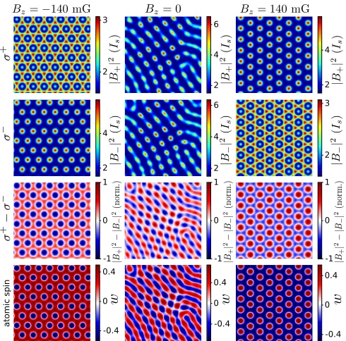
The NF images of simulated 2D patterns at three different
Bzvalues are plotted in Fig.7. At zeroBz, the patterns exhibit
a square symmetry with stripelike defects. This is similar to the experimental pattern realizations, where stripelike defects are also observed. The modulation depths of the σ beam profiles are equal, with their difference giving a lattice with neighboring sites of equal magnitude and opposite helicities. The corresponding profile of the spinwvariable mimics this behavior, with neighboring atomic spins alternating between up and down directions with equal maximal magnitudes. This constitutes an antiferromagnetic spin state. Observing the NF profiles of the σ polarization channels can thus reveal the underlying spin structure inside the atomic medium and justifies the approach taken in Fig. 2 to infer the magnetic distribution in the medium from the difference of the NF images of the circular components. For small Bz’s, the
in-version symmetry of the system is broken and patterns with hexagonal symmetry appear. For negative (positive) Bz, the
[image:6.608.50.300.69.199.2]σ+ patterns are honeycombs (hexagons) and theσ− patterns are hexagons (honeycombs), as in the experiment. The sub-tracted σ intensity profiles and the w variable both show
FIG. 7. Near-field steady-state data (depicting intensity of the reentrant feedback field B±=B˜±(z=L) and atomic orientation
w), taken from two-dimensional (2D) simulations. Columns (left to right):Bz= −140 mG,Bz=0,Bz=140 mG. Rows (top to bottom):
|B+|2,|B−|2,|B+|2− |B−|2and thewvariable. Simulation
parame-ters:b0=60,I0=15Is,= −102,R=0.95,γ=10−42,
simu-lation time: 2×10⁴/2. The size of the numerical grid was adjusted to contain seven periods of the lattice. Periodic boundary conditions are used in the simulations.
positive (negative) hexagons for positive (negative) Bz. The
modulation depth of the positive (negative) spin sublattice is greater at positive (negative) Bz, resulting in a net positive
(negative) magnetization. This constitutes a ferromagnetic spin state.
VI. ANALYTICAL CALCULATIONS
The state of the spin-1 system analyzed is determined by four coupled dynamical equations (1) for the variables
u, v, w, x, evolving on similar timescales. This situation is quite unlike most previous work in the single feedback mir-ror (SFM) configuration, where time-dependent perturbation analysis is done by considering the perturbation evolution of a single (slow) degree of freedom of the optically nonlinear medium, e.g., atomic density [5,6] or spin [29,30] in atomic media, charge carrier density in direct band-gap semicon-ductors [48], or the phase difference between ordinary and extraordinary waves in liquid crystal valves [49]. In contrast to the numerical results of Sec.V, in this section we present analytical results for a simplified model, taking into account only the perturbations and feedback to the spin-w variable. This is motivated by the numerical simulations indicating the dominance of the orientation in the magnetic ordering. Although only approximate, this model is illustrative as it provides physical explanations for the variation of thresholds and symmetries at smallBz, consistent with both experimental
model with those for a further simplifiedw-only model, which is effectively a spin-1/2 model, derived by puttingu=v= x=0 in (1) and (3), and demonstrate the inadequacy of the latter for describing the pattern properties.
A. Linear stability analysis
We now calculate the threshold intensity of the pattern formation in the spin-1 model. In writing Eqs. (3), we have made use of the thin-medium approximation, in which the cloud is diffractively thin and the patterns form due to inter-ference of the fieldsF±+B±at the end of the medium, where
F± =F±0=E0 andB±=B˜±(z=L) [50]. This is justified as the medium is sufficiently optically thin, and we use mirror positions just outside the end of the medium, so that the diffraction and the nonlinear phase shift within the medium are not the dominant effects but not so far from it to observe competition with the higher order Talbot modes [43].
The backward-propagating field re-entering the medium is of the form
B±=B0±(1+b±), (5)
whereB0±=√RE0is the homogeneous part of the backward-propagating field,Ris the mirror reflectivity, andb±are small perturbations in the field caused by a transverse perturbation in the atomic spin of the form δwcos(qx). We relate the spin perturbation withb±by usingw=wh+δwcos(qx) in
Eq. (3) (withu=v=x=0), wherewhis the homogeneous
part of the spin, and integrating Eq. (4) to the mirror and back:
b±= ±i3
4φ 0
±eiθδwcos(qx), (6)
whered is the mirror distance from the end of the medium. Homogeneous values of the atomic variables are calculated from (1) usingF±0+B0±for the electric fields. In writing the relation (6), we have neglected the influence of the perturba-tions in the higher order magnetic multipoles, as motivated by experimental and numerical results of the full model which indicate that thewvariable is the main driver of instability.
Equations (5) and (6) illustrate how the pattern formation occurs. The plane wave enters the cloud and acquires a transverse phase modulation from the atomic spins inside the medium. As we work in the thin medium approximation, we neglect the phase modulation in the forward-propagating beam at the end of the cloud, since the structured feedback by the backward-propagating beam is expected to dominate the pattern formation. In linear stability analysis (LSA), we look at the growth of an initial cosine spin perturbation with a given transverse wave numberq. The diffraction of the phase modulated beam from the end of the cloud and back causes the transverse profile to continually vary alongz, interchanging planes of phase and amplitude modulation, due to the Talbot effect [51], parametrized in our model viaθ. Sinceθdepends onq, for a given transverse perturbation there is a certainb±
at a given mirror position d. As is shown in Fig. 6(a), the fastest growing perturbations will occur for a certain critical θ, and this is in general the θ value seen in the steady-state patterns observed experimentally [37]. We will here use the critical phase shift of θ=π/2, meaning the instability maximizes modulation in the difference pump rateD, as is
consistent with both experimental and numerical data of the full model. The patterns thus grow from initial noise due to the feedback provided byb±, via the birefringent nonlinearity given by theδwterm, effectively inducing interatomic inter-actions mediated by the light field in this out-of-equilibrium system.
We are now interested in solutions corresponding to trans-verse patterns, the dynamics of which is characterized by exponential growthδw∼eλt (where λ∈IR) near threshold. Inserting this form ofδwinto the dynamical equation forw, we get forλ:
λ= −
γ+I0κ¯ 6 (1+R)
+I0whR
4 (κ+φ 0
+−κ−φ0−)
+ ¯vhI0R 4 (φ
0
+−φ−0)+
I0R
12(2xh−5)(κ+φ 0
++κ−φ0−), (7)
where uh,vh,wh,xh are the homogeneous parts of the
u,v,w,xvariables and ¯κ =κ++κ−. Setting nowλ=0, we obtain the expression for total threshold intensity It h of the
linearly polarized input pump beam:
It h=2γ
−κ¯
6(1+R)+
wt h hR
4 (κ+φ 0
+−κ−φ−0)
+ ¯vt hhR
4 (φ 0
+−φ−0)+
R
12
2xt hh−5
(κ+φ0
++κ−φ−0) −1
, (8)
where the subscript “h” and superscript “th” denominate the homogeneous and threshold parameter values, respectively. The solution (8) is inserted into Eqs. (1) to get the threshold values of the homogeneous atomic variables, which allows us to calculate theIt h.
The scan of It h (in mW/cm2) against Bz is plotted in
Fig. 8 for three different solutions: the full solution using (8), the spin-1/2 model introduced before (i.e., keepingx= u=v=0 throughout and not only in the feedback terms, but keeping the incoherent linear and nonlinear Faraday effect), and a simplified solution keepingx,u,vin the homogeneous terms but neglecting both the linear and incoherent nonlinear Faraday effects [25], i.e., settingκ±=1,φ0 =φ±0:
It h ≈
2γ −1
3(1+R)+
Rφ0 6
2xt h
h −5
. (9)
It should be noted thatφ0<0 for the red detuning condition under study. The full solution (red line) has a minimum threshold for Bz=0. It increases with incresing |Bz|. This
qualitatively mimics the small |Bz| experimental results at
b0=27. We note that we have used b0=30 in our cal-culations, as the experimental values have an estimated un-certainty of 5, and the chosen value gives a more robust agreement with experiment. At small|Bz|, the behavior is well
reproduced by Eq. (9) (see dash-dotted green line), where the
Bzdependence arises solely due toxt hh (see Fig.9). The origin
of this dependence is explained below. At larger|Bz|, the full
FIG. 8. Variation of threshold intensity withBz. Red solid curve:
full solution using (8). Green dot-dashed curve: solution for the model neglecting both linear and nonlinear Faraday effects [using (9)]. Blue dashed curve: solution ofw-only model (see text). Param-eters:= −142,R=0.95,b0=30,γ =3×10−42.
The onset of pattern formation happens at the intensity for which modulation depumping [first term in Eq. (7) stemming from the sum pump rate S term in the relaxation terms of Eqs. (1)] is equal to pumping due to the intensity modulated pump rate [last term of Eq. (7) stemming from the differ-ence pump rate Dterm]. Thexh dependence arises from the
term ∝ −Dxin the third equation of (1). Writingx as x=
FIG. 9. Homogeneous solutions of (1) at threshold, againstBz.
Coherences (a)uand (b)v, (c) alignmentxand (d) orientationw. The narrow features for smallBz are caused by magnetic field coupling
to the coherencesuandv(i.e., coherent nonlinear Faraday rotation), whereas the features at largeBz are caused by linear and nonlinear
Faraday rotation due to detuning via Zeeman shifts (see text). This is confirmed by the solution of thew-only model, represented by the blue dash-dotted curve of panel (d). The scan is representative of the single-pass behavior for theF=1→F=2 transition at low pump saturation. Parameter values are as in Fig.8.
1−3ρ00 (using ρ−1−1+ρ00+ρ11 =1), this term becomes −Dx=D(3ρ00−1). Thus, for D>0 (D<0) an increase of population in the m=0 state will increase the effective pumping rate of the spin into them=1 (m= −1) state. The origin of the variation ofxt h
h at small|Bz|is in the coupling
term −13P+u of the fourth equation in (1), the details of which will be explained at the end of this section. In short, Fig.9shows that the coherent nonlinear Faraday effect creates a magneto-optical resonance for the coherences u, v. The resonance in u couples to x, which reduces (increases) the spin modulation pump rate and thus increases (reduces) the threshold, for larger (smaller)x[see Eq. (9)]. The resonance invcouples to thewand causes it to rotate inBz, which leads
to the deviation of the full andw-only solutions in Fig.9(d), as explained at the end of this section.
The dashed curve in Fig. 8 is for the spin-1/2, w-only, model, which includes both linear and incoherent nonlinear Faraday effects. It does not show aBzdependence. The large
difference between this and the solid threshold curve at all
Bz shows that thew-only model cannot account for theBz
dependence of the experimental threshold intensity presented in Fig. 4(b). This demonstrates that the system at hand is more complex and potentially more rich than the previously studied spin-1/2 model of Refs. [29,30]. Threshold curves of the instability versus Bz for a spin-1/2 system presented in
Ref. [52] were all obtained in small transverse magnetic fields and their extrapolation to zero transverse field is compatible with a flat threshold curve versusBz.
The decrease of threshold with largeBzseen in experiments
is not reproduced by any of these models at these parameter values, which leads us to the conclusion that the perturbations in the higher order magnetic multipoles are responsible for a threshold decrease at large Bz, implied by the results in
Fig.6(b).
B. Inversion symmetry breaking
To calculate the symmetries of patterns at threshold, we employ the method of nonlinear analysis (NLA) used by D’Alessandro and Firth for SFM patterns in a Kerr medium [48]. We will reformulate our problem as a single partial differential equation of infinite order, describing the temporal evolution of spin perturbation δw˜, and end up with a set of Ginzburg-Landau equations for the roll state amplitudes, from which we calculate the variation of the allowed pattern symmetries withBz.
The backward-propagating fields B± reflected from the mirror and re-entering the medium can be related to the fields exiting the medium by formally integrating the free space diffraction equation to the mirror and back, giving
B±=√RE0e−iσ ⊥e±i 3φ0
±
4 δw˜, (10)
whereσ =d/kand we use an ansatz for the modulationδw˜:
δw˜ =ε(A1(t)eiq1·r+A2(t)eiq2·r+A3(t)eiq3·r+c.c.)/2, (11)
where ε is a bookkeeping parameter. This solution corre-sponds to a superposition of three roll states with wave vectors
[image:8.608.49.296.458.636.2]intensities near threshold. For the input pump intensities of the σ components, we will thus use|F+|2= |F
−|2=I0=pIt h/2,
where the parameterpis close to 1.
Inserting the field (10) into the dynamical equation for w
yields an infinite order equation for temporal evolution of the perturbationδw˜
δw˙˜ + γ+I0 6
¯
κ+Rκ+e−iσ ⊥ei
3φ0
+
4 δw˜2+κ−e−iσ ⊥e−i 3φ0
−
4 δw˜2δw˜
= −I0whR
6
κ+e−iσ ⊥ei
3φ0
+
4 δw˜2+κ−e−iσ ⊥e−i 3φ0
−
4 δw˜2−κ¯
+ ¯I0uhR
3 Im
eiσ ⊥e−i3φ
0
+
4 δw˜e−iσ ⊥e−i 3φ0
−
4 δw˜ −1− ¯ I0vhR
3 Re
eiσ ⊥e−i3φ
0
+
4 δw˜e−iσ ⊥e−i 3φ0
−
4 δw˜ −1
+ I0R 9
5 2−xh
κ+e−iσ ⊥ei 3φ0
+
4 δw˜2−κ−e−iσ ⊥e−i 3φ0
−
4 δw˜2−κ, (12)
where ¯κ=κ++κ− andκ =κ+−κ−. From Eq. (12), we derive the dynamical equations for the perturbation
am-plitudes in the following way. First, we expand e±i
3φ0
±
4 δw˜, using (11), to second order in ε. After this, we evaluate
e−iσ ⊥e±i
3φ0
±
4 δw˜ andeiσ ⊥e±i 3φ0
±
4 δw˜ by noting the propagation operatore−iσ ⊥ is eiθ in Fourier space. This means we can multiply the uniform (q=0) terms by 1, terms with wave vectors of lengthqbyeiθ, terms with wave vectors of length
√
3q by e3iθ, etc.; i.e., each term is an eigenfunction of the
propagation operator. After this, the terms|e−iσ ⊥e±i3φ
0
±
4 δw˜|2 andeiσ ⊥e−i3φ
0
+
4 δw˜e−iσ ⊥e−i 3φ0
−
4 δw˜ are calculated, again by tak-ing into account only expansion up to second order inε. The calculation is simplified by our assumption that only terms resonant with qc are non-negligible, implicit in writing the
ansatz (11) for δw˜. As we are here primarily interested in the existence of hexagonal solutions, we use the condition
q1+q2+q3=0.
After equating the two sides of (12) and puttingε=1, we get the equations of the form
d
dtAi=λAi+ηA
∗
jA∗k+ · · · (13)
for the amplitudes A1(t), A2(t), A3(t). Equations (13) de-scribe mixing of modes on the same Talbot circle, to low-est orders in amplitude. They have the form of complex Ginzburg-Landau equations, common in many nonlinear sys-tems [37,48,53]. The first term gives an exponential decrease or increase in amplitude of the transverse wave, with its vanishing determining the onset of instability. We regain here the threshold intensity of (8). The second (quadratic) term describes mixing of the three modes of a hexagon. It can easily be shown that positive (negative) hexagons are stable at threshold for η >0 (η <0), whereas stripes, squares, or rectangles are stable at threshold for η=0 [37,48]. For the current purpose, it is sufficient to look for a single mode (i.e., stripes) as a representative for the inversion-symmetric, i.e., antiferromagnetic, state. In a more complete analysis, one could include an additional set of modes with wave vectors rotated by 90◦ to include the square state, but this does not add any insight into the mechanism of the symmetry breaking from the antiferromagnetic to the ferrimagnetic states.
Upon inserting the critical diffractive phase shift ofθc=π2,
the coefficientλis given by relation (7) andηis
η=
3 4
2
RIt hp
2 8 9[κ+φ
0
+−κ−φ−0]
−wh
3 [κ+(φ 0
+)2+κ−(φ0−)2]
+¯uh
3 [(φ 0
+)2−(φ0−)2]+ 2 ¯vh
3 φ
0 +φ−0
+2 9
5 2 −xh
[κ+(φ+0)2−κ−(φ−0)2]
. (14)
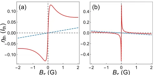
We now concentrate on the scan of threshold η against
Bz. In Fig. 10, we plot ηt h against Bz for two different b0 values, corresponding to Strathclyde [Fig. 10(a)] and Nice [Fig. 10(b)] parameters. For Bz=0, we have ηt h=0, and
the system is inversion symmetric, as also witnessed in the fact that wt h
h =0 [see Fig. 9(d)]. For small |Bz|, there is a
strong increase (decrease) in ηt h for Bz>0 (Bz<0). This
agrees with the results of both experiments and simulations for a spin-1 model. The behavior of ηt h at small |Bz| is
determined bywt h h andv
t h
h , giving a dispersive feature due to
their coefficients in (14) being an even function in Bz [and
wt h h,v
t h
h being odd inBz; see Figs.9(b)and9(c)]. We note that
simulations of the spin-1/2 model failed to produce hexagons at small|Bz|, indicating that the coupling to higher multipoles
[image:9.608.313.559.581.702.2]is indeed responsible for the symmetry breaking.
FIG. 10. Dependence of the thresholdηcoefficient onBz. (a)
In zeroBfield, the linearly polarized pump beam induces am=2 coherence between them=1 andm= −1 states via them=0 excited state with the real partubeing pumped and the imaginary partvbeing zero [see Figs.9(a)and9(b)]. The atomic coherence rotates inBzdue to Larmor precession.
This gives rise to the steady-state curves in Figs.9(a)and9(b)
with an even shape for ut h and a dispersive (odd) shape for
vt h. This is the dominant origin of symmetry breaking. The
variation ofwt hh at small|Bz|is due to coupling withvht h[see
Fig.9(b)], given by the−16P+¯vterm of the third equation of (1), whereas in a spin-1/2 model a symmetry breaking due
to the incoherent Faraday effect is present (see dashed blue line) but much smaller than the effect due to the coupling to
v. This coupling is a signature of coherent nonlinear Faraday rotation, and its physical origin will be explained at the end of this section.
At higher |Bz|, the magnitude of theη coefficient starts
to decrease, as both coherences u, v are destroyed by the precession. For even higher fields, it starts to slowly increase again (for smallb0) or flips its sign (for largeb0). This qual-itatively agrees with the experimental data, where a flipping of the direction of the hexagons was observed for large b0. The sign reversal at high b0 is present also in the spin-1/2 model. Its origin is in the competition of the three terms of the spin-1/2 model, where the last term [originating from the
D(5/18−x/9) term in the third Eq. of (1)] has a negative slope at largeBz(and large negative ¯) and is responsible for
the flipping. These slopes are determined by the incoherent linear and nonlinear Faraday effects, i.e., the variation of κ± andφ0
± withBz. The physical interpretation of the said
competition is still under investigation.
We note that in previous experiments in spin-1/2 sodium vapors a change of inversion symmetry was not observed with varying a longitudinal magnetic field alone [50,52,54], in line with the theoretical treatment given here, as the incoherent Faraday effect is very small for the pressure broadened transi-tion under study in Refs. [50,52,54]. A symmetry-breaking transition was only obtained in a transverse magnetic field [50,54] or by perturbing the input polarization to be elliptical [29,30]. In the former case, the interplay of dark state pumping of wh and spin flips in the transverse field is influenced by
not only the Zeeman shifts but also the light shift changing the ground-state degeneracy, and the effect was accompanied by a large asymmetry in the absorption of the two circular light components. Such large absorption asymmetry was not observed for our system parameters at small Bz, either in
experiments or simulations. In the case of elliptical input polarization, the symmetry of optical pumping is obviously broken. We expect a similar effect in the cold-atom system but did not investigate it further as the analogy between mag-netic ordering via light-induced interactions and in condensed matter systems, respectively, simple models for magnetism, is better worked out by changing the magnetic field than the input polarization.
C. Coupling of magnetic multipoles
We now explain the physical mechanisms for breaking of inversion symmetry and increase of threshold at small |Bz|
in the simplified model used throughout this section. It is
well known that quantum interference effects can influence the steady state of a laser-driven system in a(-like) configu-ration, depending on the phase of the ground-state coherence density matrix element [55]. It is thus natural to expect that the change of the values ofuhandvhshould influence our results
at small|Bz|.
The change of symmetry at small|Bz|was already seen to
occur due to coupling ofwh andvh. To see the origin of this
coupling, we will switch to the usual representation of density matrix elements in the Zeeman sublevel basis. For simplicity, we put + =−=0,0∈IR (i.e., beam is linearly po-larized alongy). We are interested in coupling of the optical coherenceρ10 (where the apostrophe denotes a sublevel of the excited state) to the populationρ11and atomic coherence ρ1−1. After adiabatic elimination, the optical coherence is given by
ρ10 = 0
6
ρ11+ρ1−1
i2−
, (15)
where we have here neglectedz with respect to in the
denominator (as for smallBz,|| |z|) and we note that
the same expression appears in a system (as given, e.g., in [56], apart from the sign convention and with excited-state population here being neglected). We also note that for putting +=0 and keeping −=0, theρ1−1 term in (15) van-ishes. The relevant term in the dynamical equation forρ11is
˙
ρ11∝20Im(ρ10). (16)
The ρ11 term in (15) is due to population leaving the state with m=1 and is contained in the decay rate w of (1).
Keeping only theρ1−1term, (16) is now
˙ ρ11 ∝ −
I0
3Im(ρ¯ 1−1), (17)
where we have neglected the 2 term with respect to the term as it cancels out in the w equation (but not for x; see below). The dynamical equation forρ−1−1 has the same dependence on Im(ρ1−1) but with a positive sign, which gives the−1
6¯P+v term in thew equation of (1). For a finitev, an optical coherence in the configuration can thus give rise to optical pumping of a stretched state with m= ±1, depending on the sign of v. We interpret this process as coherent two-photon Raman pumping.
The importance of light-induced|m| =2 Zeeman coher-ences for nonlinear Faraday rotation in anF →F+1 (with
F 1) transition was noted in Refs. [36,44], where amplitude modulation of light [57] was used to detect narrow resonances in the demodulated in-phase rotation signals. Resonances at twice the Larmor frequencies equal to intensity modulation frequencies were interpreted to arise due to beating of the oscillating light-induced Zeeman coherences and Larmor pre-cession caused by a longitudinal magnetic field. By writing and solving Eqs. (1), the experimental results of these papers are corroborated and their theoretical analysis made more concrete, albeit in a simpler level structure, expected to exhibit equivalent behavior.
Increase of threshold intensity with increasing|Bz|at small
|Bz|is a consequence of the reduction of population in them=
of this coupling is the excited-state population ρ00, which is in our derivation of (1) adiabatically eliminated but still “feeds” the ground-state populations. Using the assumptions made above, one gets for the coupling of the excited-state pop-ulation inm=0 and the ground state|m| =2 coherence
ρ00 ∝
I0 31
Re(ρ1−1), (18)
as is apparent also from the equations of Ref. [56] for a system. The above expression indicates that a large (small) value ofuleads to large (small) population of the excited state withm=0. The optical coherencesρ10 andρ−10 are also affected by Re(ρ1−1), which leads to the following terms in the dynamical equations forρ11andρ−1−1,
˙
ρ11,ρ−˙ 1−1∝ −
I0
3Re(ρ1−1), (19)
which together with (18) leads to the−13P+u term in the fourth equation of (1). Since u decreases with increasing |Bz| at small |Bz|, the ρ00 will also decrease. The m=0 population relative to the total stretched state populations will likewise decrease, since the probability of decay ofρ00 into
m=0 is two times greater than for decay into m=1 and
m= −1 together [see Fig. 5(a)]. This decrease of relative population in m=0 as |Bz| grows from zero to a small
value leads hence to an increase inx. This then leads to an increase in the threshold intensity, as explained in Sec.VI A
[see Eq. (9)].
VII. CONCLUSION
We have studied the properties of transverse spin patterns in a cold atomic cloud of87Rb subject to laser driving with mirror feedback. Experimental scans of pattern properties against longitudinal magnetic field were compared to the mostly analytical results of our spin-1 theoretical model. Inversion-symmetric antiferromagnetic spin patterns give way to ferrimagnetic patterns in a weak longitudinal magnetic field. It was worked out that the inversion symmetry of the system, governing the pattern symmetries, is broken for small magnetic fields by coupling of the dipole magnetic polarization of the atoms to the|m| =2 ground state co-herence precessing in theBz field. This is consistent with the
conclusion of Faraday rotation studies performed in a cold atomic cloud with similar level structure [36]. The increase of threshold intensity for pattern formation with small magnetic field is in our model a result of reduced pump rates into the stretched states caused by the coupling of the quadrupolar polarization components, whereas perturbations in the higher order magnetic moments are responsible for threshold reduc-tion at larger magnetic fields. The spin-1 model thus accounts for the experimental dependence of pattern properties on the longitudinal magnetic field, exhibiting dependence on both dipole and quadrupole magnetic components of the density matrix expansion. This constitutes a step beyond previous work on spin-1/2 models [8,27,29,30,50,54]. Optical interfer-ence in Rb vapors with multilevel structure has recently been employed to observe interesting linear [58] and nonlinear [59] optical effects.
Our cold-atom setup has some analogy with the Ising model, where interactions are light mediated over a range determined by diffractive dephasing, and the lattice emerges spontaneously as opposed to it being set externally [25]. The work is part of a relatively recent research effort of using laser light as an atomic interaction vector, due to its easy controllability and extremely weak decoherence of its states during propagation. In recent years various setups, from cavities to nanoscopic solid state devices, have been employed to engineer photon-mediated interactions between atoms for a wide range of quantum technological purposes [60–62]. Self-organization phenomena in driven systems have for a long time played an important technological role, from the invention of the laser [63] to recent promising applications in frequency combs [64] and chemical engineering [65]. It is thus interesting to ask whether and how self-organization will find its application in next-generation quantum technologies. The SFM setup may offer some advantages in this respect, and we will continue to explore its quantum technological potential with both thermal and degenerate cold atoms. For example, Ref. [25] reports indication of a hysteretic first-order phase transition between the unstructured and the fer-rimagnetic state, opening the exciting possibility to study nucleation phenomena and localized magnetic states. Also, by incorporating different geometries in the feedback part of the setup, e.g., by using a spatial light modulator, we expect to be able to engineer different forms of light-mediated interactions, which is a very attractive feature for quantum simulation.
Although the pattern length scale is here set by the mirror distance and the allowed symmetry at threshold is set byBz,
the transverse pattern spin modes are degenerate in the sense that a pattern realization with any orientation and center posi-tion is equally probable. This multimode situaposi-tion is inherent in the SFM setup and arises due to transverse rotational and translational symmetries of the initial system. Light-mediated self-organization of atomic degrees of freedom in multimode configurations is currently generating some interest, with pos-sible broader implications for the field of condensed-matter physics [4–13]. In addition to the optomechanical effects, spinor effects have sparked interest in this community as well [15,18].
ACKNOWLEDGMENTS
[1] I. D. Leroux, M. H. Schleier-Smith, and V. Vuletic,Phys. Rev. Lett.104,073602(2010).
[2] M. H. Schleier-Smith, I. D. Leroux, and V. Vuleti´c,Phys. Rev. Lett.104,073604(2010).
[3] M. A. Norcia, R. J. Lewis-Swan, J. R. Cline, B. Zhu, A. M. Rey, and J. K. Thompson,Science361,259(2018).
[4] S. Gopalakrishnan, B. L. Lev, and P. M. Goldbart,Phys. Rev. A
82,043612(2010).
[5] G. Labeyrie, E. Tesio, P. M. Gomes, G.-L. Oppo, W. Firth, G. Robb, A. Arnold, R. Kaiser, and T. Ackemann,Nat. Photon.8,
321(2014).
[6] E. Tesio, G. R. M. Robb, T. Ackemann, W. J. Firth, and G.-L. Oppo,Phys. Rev. Lett.112,043901(2014).
[7] Y.-C. Zhang, V. Walther, and T. Pohl, Phys. Rev. Lett. 121,
073604(2018).
[8] B. L. Schmittberger and D. J. Gauthier,New J. Phys.18,103021
(2016).
[9] S. Ostermann, F. Piazza, and H. Ritsch,Phys. Rev. X6,021026
(2016).
[10] I. Dimitrova, W. Lunden, J. Amato-Grill, N. Jepsen, Y. Yu, M. Messer, T. Rigaldo, G. Puentes, D. Weld, and W. Ketterle,
Phys. Rev. A 96,051603(R)(2017).
[11] G. R. M. Robb, E. Tesio, G.-L. Oppo, W. J. Firth, T. Ackemann, and R. Bonifacio, Phys. Rev. Lett. 114, 173903
(2015).
[12] J. Léonard, A. Morales, P. Zupancic, T. Esslinger, and T. Donner,Nature (London)543,87(2017).
[13] F. Mivehvar, S. Ostermann, F. Piazza, and H. Ritsch,Phys. Rev. Lett.120,123601(2018).
[14] J. Léonard, A. Morales, P. Zupancic, T. Donner, and T. Esslinger,Science358,1415(2017).
[15] M. Landini, N. Dogra, K. Kroeger, L. Hruby, T. Donner, and T. Esslinger, Phys. Rev. Lett. 120, 223602
(2018).
[16] A. J. Kollár, A. T. Papageorge, V. D. Vaidya, Y. Guo, J. Keeling, and B. L. Lev,Nat. Commun.8,14386(2017).
[17] S. C. Schuster, P. Wolf, D. Schmidt, S. Slama, and C. Zimmermann, Phys. Rev. Lett. 121, 223601
(2018).
[18] R. M. Kroeze, Y. Guo, V. D. Vaidya, J. Keeling, and B. L. Lev,
Phys. Rev. Lett.121,163601(2018).
[19] T. Keller, V. Torggler, S. B. Jäger, S. Schütz, H. Ritsch, and G. Morigi,New J. Phys.20,025004(2018).
[20] W. J. Firth,J. Mod. Opt.37,151(1990).
[21] L. Lugiato, F. Prati, and M. Brambilla, Nonlinear Optical Systems(Cambridge University Press, Cambridge, UK, 2015). [22] M. Tamburrini, M. Bonavita, S. Wabnitz, and E. Santamato,
Opt. Lett.18,855(1993).
[23] T. Ackemann and W. Lange,Phys. Rev. A50,R4468(1994). [24] A. Camara, R. Kaiser, G. Labeyrie, W. J. Firth, G.-L. Oppo,
G. R. M. Robb, A. S. Arnold, and T. Ackemann,Phys. Rev. A
92,013820(2015).
[25] I. Kreši´c, G. Labeyrie, G. R. M. Robb, G.-L. Oppo, P. M. Gomes, P. Griffin, R. Kaiser, and T. Ackemann,Commun. Phys.
1,33(2018).
[26] G. Labeyrie, I. Kreši´c, G. R. M. Robb, G.-L. Oppo, R. Kaiser, and T. Ackemann,Optica5,1322(2018).
[27] F. Mitschke, R. Deserno, W. Lange, and J. Mlynek,Phys. Rev. A33,3219(1986).
[28] G. Grynberg,Opt. Commun.109,483(1994).
[29] A. J. Scroggie and W. J. Firth,Phys. Rev. A53,2752(1996). [30] A. Aumann, E. Büthe, Y. A. Logvin, T. Ackemann, and W.
Lange,Phys. Rev. A56,R1709(1997).
[31] B. L. Schmittberger and D. J. Gauthier, JOSA B 33, 1543
(2016).
[32] G. A. Muradyan, Y. Wang, W. Williams, and M. Saffman, in Nonlinear Guided Waves and Their Applications (Optical Society of America, 2005), p. ThB29.
[33] J. A. Greenberg, B. L. Schmittberger, and D. J. Gauthier,
Opt. Express 19,22535(2011).
[34] B. L. Schmittberger and D. J. Gauthier,Phys. Rev. A90,013813
(2014).
[35] J. Dalibard and C. Cohen-Tannoudji,JOSA B6,2023(1989). [36] A. Wojciechowski, E. Corsini, J. Zachorowski, and W. Gawlik,
Phys. Rev. A81,053420(2010).
[37] M. C. Cross and P. C. Hohenberg,Rev. Mod. Phys.65,851
(1993).
[38] E. Ciaramella, M. Tamburrini, and E. Santamato,Appl. Phys. Lett.63,1604(1993).
[39] M. A. Neto and J. R. de Sousa, Phys. Lett. A 330, 322
(2004).
[40] T. Kaneyoshi,J. Magn. Magn. Mat.406,83(2016).
[41] P. Kushwaha, R. Rawat, and P. Chaddah,J. Phys.: Condens. Matter20,022204(2008).
[42] S. M. Yusuf, N. Thakur, M. Medarde, and L. Keller,J. Appl. Phys.112,093903(2012).
[43] W. J. Firth, I. Kreši´c, G. Labeyrie, A. Camara, and T. Ackemann,Phys. Rev. A96,053806(2017).
[44] W. Gawlik and A. Wojciechowski,A. Opt. Spectrosc.111,626
(2011).
[45] I. Kreši´c, Ph.D. thesis, University of Strathclyde, Glasgow, United Kingdom, 2016.
[46] M. Auzinsh, D. Budker, and S. Rochester,Optically Polarized Atoms: Understanding Light-Atom Interactions(Oxford Univer-sity Press, Oxford, UK, 2010).
[47] M. Fleischhauer, A. Imamoglu, and J. P. Marangos,Rev. Mod. Phys.77,633(2005).
[48] G. D’Alessandro and W. J. Firth, Phys. Rev. A 46, 537
(1992).
[49] R. Neubecker, G.-L. Oppo, B. Thuering, and T. Tschudi,
Phys. Rev. A 52,791(1995).
[50] Y. A. Logvin, A. Aumann, M. Tegeler, T. Ackemann, and W. Lange, J. Opt. B: Quantum Semiclassical Opt. 2, 426
(2000).
[51] H. F. Talbot,London Edinburgh Phil. Mag. J. Sci.9,401(1836). [52] A. Aumann, Ph.D. thesis, Westfalische Wilhelms-Universität,
Muenster, Germany, 1999.
[53] I. S. Aranson and L. Kramer,Rev. Mod. Phys.74,99(2002). [54] A. Aumann, E. G. Westhoff, T. Ackemann, and W. Lange,
J. Opt. B: Quantum Semiclassical Opt. 2,421(2000). [55] J. P. Marangos,J. Mod. Opt.45,471(1998).
[56] R. G. Brewer and E. L. Hahn,Phys. Rev. A11,1641(1975). [57] W. Gawlik, L. Krzemie´n, S. Pustelny, D. Sangla, J.
Zachorowski, M. Graf, A. Sushkov, and D. Budker,Appl. Phys. Lett.88,131108(2006).
[58] Z. Zhang, Y. Zhang, J. Sheng, L. Yang, M.-A. Miri, D. N. Christodoulides, B. He, Y. Zhang, and M. Xiao,Phys. Rev. Lett.
117,123601(2016).
[60] H. Ritsch, P. Domokos, F. Brennecke, and T. Esslinger,
Rev. Mod. Phys. 85,553(2013).
[61] G. Kurizki, P. Bertet, Y. Kubo, K. Mølmer, D. Petrosyan, P. Rabl, and J. Schmiedmayer,Proc. Natl. Acad. Sci. USA112,
3866(2015).
[62] D. E. Chang, J. S. Douglas, A. González-Tudela, C.-L. Hung, and H. J. Kimble,Rev. Mod. Phys.90,031002(2018).
[63] A. L. Schawlow and C. H. Townes, Phys. Rev. 112, 1940
(1958).
[64] T. J. Kippenberg, A. L. Gaeta, M. Lipson, and M. L. Gorodetsky, Science 361, eaan8083
(2018).
[65] Z. Tan, S. Chen, X. Peng, L. Zhang, and C. Gao,Science360,
![FIG. 8. Variation of threshold intensity with Bfull solution using (model neglecting both linear and nonlinear Faraday effects [using(eters:9)]](https://thumb-us.123doks.com/thumbv2/123dok_us/1342687.87983/8.608.67.276.67.272/variation-threshold-intensity-solution-neglecting-nonlinear-faraday-effects.webp)