LARGER
MW-CLASS
FLOATER
DESIGNS
WITHOUT
UPSCALING?
A
DIRECT
OPTIMIZATION
APPROACH
Mareike Leimeister∗
Naval Architecture, Ocean and Marine Engineering University of Strathclyde
Glasgow G4 0LZ, United Kingdom Division Load Calculation and System Dynamics Fraunhofer IWES, Institute for Wind Energy Systems
Am Luneort 100, 27572 Bremerhaven, Germany
Athanasios Kolios, Maurizio Collu Naval Architecture, Ocean and Marine Engineering
University of Strathclyde Glasgow G4 0LZ, United Kingdom
Philipp Thomas
Division Load Calculation and System Dynamics Fraunhofer IWES, Institute for Wind Energy Systems
Am Luneort 100, 27572 Bremerhaven, Germany
ABSTRACT
The trend towards larger offshore wind turbines (WTs) im-plies the need for bigger support structures. These are commonly derived from existing structures through upscaling and subse-quent optimization. To reduce the number of design steps, this work proposes a direct optimization approach, by which means a support structure for a larger WT is obtained through an au-tomated optimization procedure based on a smaller existing sys-tem. Due to the suitability of floating platforms for large MW-class WTs, this study is based on the OC3 spar-buoy designed for the NREL 5 MW WT. Using a Python-Modelica framework, developed at Fraunhofer IWES, the spar-buoy geometry is ad-justed through iterative optimization steps to finally support a 7.5 MW WT. The optimization procedure focuses on the global system performance in a design-relevant load case. This study shows that larger support structures, appropriate to meet the ob-jective of the hydrodynamic system behavior, can be obtained through automated optimization of existing designs without the intermediate step of upscaling.
Keywords: upscaling, automated design optimization, float-ing platforms, offshore wind turbines, Modelica, MoWiT, Python, IWT-7.5-164, OC3.
∗Contact author: [email protected].
NOMENCLATURE
DBC Bottom cylinder diameter. DTC Top cylinder diameter.
dBC,b Distance to base of bottom cylinder. dBC,t Distance to top of bottom cylinder. dTC,b Distance to base of top cylinder. dTC,t Distance to top of top cylinder.
g Gravitational acceleration (≈9.81 m/s2). hballast Ballast filling height.
hBC Height of bottom cylinder. KI Integral controller gain. KP Proportional controller gain.
ζc Damping ratio of the response.
ρballast Ballast density.
ωc,nat Controller natural frequency of the response.
INTRODUCTION
Exploitation of deeper waters and installation of larger wind turbines (WTs) are current and future trends of the offshore wind industry. Different platforms are developed and prototypes of floating offshore wind turbines (FOWTs) are already installed and tested; however, floating support structures still need to
Proceedings of the ASME 2019 38th International Conference on Ocean, Offshore and Arctic Engineering OMAE2019 June 9-14, 2019, Glasgow, Scotland, UK
conform with the increasing scale of WTs. The design process of (floating) wind turbine systems is very extensive and of iterative character. However, to avoid designing a floating support structure for a larger WT completely from scratch, advantage is taken of the experience with existing systems and upscal-ing procedures are used for dimensionupscal-ing larger structures. Notwithstanding, subsequent optimization and modification are required to obtain an efficient final design, as standard upscaling procedures are only suitable for obtaining a first rough draft of an upscaled design. As discussed in [1], the theoretical scaling laws do not account for technological developments, such as lighter and high-strength materials for rotor blades, site-specific conditions and constraints, or further improvements due to, for example, economic interests. Thus, based on the upscaled support structure design, further modifications and optimization steps have to be performed until the final floater design for a larger WT is obtained.
To save effort, this work proposes the design of a floating platform for a larger WT, which is directly obtained through optimization, thus, eliminating the intermediate step of upscal-ing. By means of this approach, only a few initial adaptions are required to consider the changed WT weight, hence ensuring floatation, and to take account of the new WT tower base diam-eter. All other modifications of the floating support structure are covered within an optimization procedure, which is based on user-defined design variables, value ranges, and optimization criteria. The result of this automatic optimization is then a support structure design, which is suited for a pre-defined larger WT and specified site, and is also optimized with respect to user-defined criteria.
In this paper, the OC3 (Offshore Code Comparison Collab-oration) phase IV spar-buoy FOWT system [2] serves as basis for the application of the direct optimization approach. By this means, a support structure for a 7.5 MW WT (Fraunhofer’s IWT-7.5-164 [3]) shall be obtained from a floater, which is initially designed for a 5 MW WT (NREL 5 MW [4]). Thus, first, the reference systems are introduced. Afterwards the methodology is explained, comprising the model setup of the FOWT system and the generic structure and functionality of the optimization framework. On this basis, the specific design conditions, such as the design variables, optimization criteria, simulation load case, and optimization parameters, are set. The results show the de-velopment of the design throughout the optimization process, as well as the final floater design for the 7.5 MW WT and its per-formance. Some discussion and conclusion round off this paper.
REFERENCE CASE
[image:2.612.319.569.69.281.2]In this study, the OC3 spar-buoy [2], supporting the NREL 5 MW WT [4], is used as basis FOWT system and hence as input
FIGURE 1. THE OC3
SPAR-BUOY FOWT SYSTEM [2].
FIGURE 2. PARAMETERS OF
THE OC3 SPAR-BUOY.
to the direct optimization approach, with the final goal to obtain a floating spar-buoy, which suits the 7.5 MW IWT-7.5-164 WT [3]. These two reference structures are introduced hereinafter.
1.1 The Basis FOWT System
The OC3 phase IV FOWT system [2] consists of a floating spar-buoy, which supports the NREL 5 MW WT [4], as visual-ized in Fig. 1. The main parameters of the FOWT system are given in Tab. 1, focusing on the spar-buoy geometry, as this is to be modified during the direct optimization approach, but also in-cluding the system masses, to be able to correct for the changed masses of tower and rotor-nacelle assembly (RNA) of the WT on top of the floater when scaling up. The geometrical parameters are defined according to Fig. 2, with the distances set in relation to the still water level (SWL).
1.2 The Larger MW-Class WT
TABLE 1. PROPERTIES OF THE OC3 FOWT SYSTEM [2, 4].
Parameter Symbol Value
RNA mass 350.0 tn
Tower mass 249.7 tn
Hub height 90.0 m
Tower base diameter 6.5 m
Top cylinder diameter DTC 6.5 m
Bottom cylinder diameter DBC 9.4 m
Distance to top of top cylinder dTC,t 10.0 m
Distance to base of top cylinder dTC,b 4.0 m
Distance to top of bottom cylinder dBC,t 12.0 m
Distance to base of bottom cylinder dBC,b 120.0 m
Height of bottom cylinder hBC 108.0 m
Platform mass including ballast 7,466.3 tn
TABLE 2. PROPERTIES OF THE IWT-7.5-164 [3].
Parameter Symbol Value
RNA mass 536.8 tn
Tower mass from 10 m above SWL 491.5 tn
Hub height 111.6 m
Tower top diameter 3.0 m
Tower base diameter 7.0 m
METHODOLOGY
To generate a new floater design for a larger MW-class WT on the basis of a smaller existing FOWT system, first, the FOWT system has to be modelled, comprising the basis design, replac-ing the WT, and adjustreplac-ing some parameters to ensure system con-formity. This model is then further processed within an optimiza-tion framework. The modeling and optimizaoptimiza-tion environments are described in the following.
2.1 Model Setup
The FOWT system is modeled in MoWiT (Modelica for Wind Turbines)1, a library established at Fraunhofer IWES.
[image:3.612.40.290.100.335.2]1Formerly OneWind Modelica library.
FIGURE 3. THE OC3 FOWT SYSTEM MODELLED IN MoWiT
AND SIMULATED IN DYMOLA [5].
MoWiT uses the object-oriented and equation-based modeling language Modelica and is capable of performing fully-coupled aero-hydro-servo-elastic simulations of WT systems. The hier-archical structure and multibody approach in Modelica allow for component-based modelling, which is of high value for the pur-pose of this study. With respect to the hydrodynamics, which are of high importance for a floating system, the MoWiT library ac-counts for hydrodynamic loads following a modified version of the MacCamy-Fuchs approach (to consider the relative motion between the structure and the fluid in addition to capturing the variation of the added inertia coefficient and including diffrac-tion effects), as well as the drag term of the Morison equadiffrac-tion (for taking into account the viscous forces). The buoyancy force and righting moment are calculated in time-domain depending on the actual local surface elevation and the current position of the FOWT system. [5–7]
2.1.1 Implementation of the OC3 FOWT in MoWiT According to the definitions given in [2], the OC3 FOWT system is implemented in MoWiT as visualized in Fig. 3, using Dymola as simulation engine. The modeling happens component-based as explained in [5], meaning that the entire system is split up into separate models for the support structure - comprising tower, floater, and mooring lines -, the nacelle with drivetrain and gen-erator, the rotor - covering the blades and the hub -, the operat-ing control, as well as two environmental models for wind and waves, including currents. In a separate study [8] the model of the spar-buoy FOWT is verified, using the code-to-code compar-isons within the OC3 phase IV project [9].
[image:3.612.47.287.384.494.2]submodel within the support structure model. However, due to the different WT dimensions (mass and tower base diameter), some initial adaptions are required before the model can be given as input to the optimization framework.
Thus, the spar-buoy geometry is partially modified by increasing the top cylinder diameter from the initial 6.5 m to 7.0 m to fit the new tower base diameter of the IWT-7.5-164. This changed parameter affects the floater structural mass for the top cylinder and the tapered part up to 12.0 m below SWL, but also the displaced water volume from 12.0 m below SWL to the water line. The change in the equivalent buoyancy mass and the structural mass can be determined directly from the original and modified spar-buoy geometry. Hence, the buoyancy mass is increased by around 46.7 t, while the floating structure becomes heavier by 8.9 t. Furthermore, the exchanged WT on top of the floater results in an additional mass increase by 428.6 t. These changed buoyancy and structural masses are accounted for in the determination of the ballast height, which is internally calculated in the model to ensure floatation of the FOWT system, and yield a ballast filling height of 45.38 m for this initially adapted FOWT system.
Furthermore, the WT controller needs to be adjusted to avoid negative aerodynamic damping, as now the IWT-7.5-164 is on top of a floating platform. For this purpose, the integral and pro-portional controller gainsKIandKPare modified, following the general descriptions and recommendations given in [10], as well as adopting the approach used in [1]. Hence, the damping ratio of the response ζc, required for the determination ofKP, is set equal to 0.7. In addition, the controller natural frequency of the responseωc,natneeds to be defined. As the controller should be slower than the system response, the pitch natural frequency of the OC3 FOWT system, obtained by the MoWiT model, is taken and reduced by a factor of 1.3, according to [1]. This yields a controller natural frequency ofωc,nat=0.1527rad/s. Together with the 7.5 MW WT specific drivetrain and blade-pitch con-troller parameters, the concon-troller gains are computed and set to KI=0.00141924 andKP=0.01300953s.
2.2 Optimization Framework in Python
This model of the FOWT system, consisting of the OC3 spar-buoy and the IWT-7.5-164 WT with the required initial adaptions, as described in Section 2.1, is given as input to the optimization framework. The optimization framework itself is based on the Python-Modelica framework, developed at Fraunhofer IWES for automated simulation, using the extension for automated optimization [11]. Working with Python as programming interface, existing packages can be utilized, by which means the interface between the programming tool Python, the modeling environment Modelica, and the simulation
engine Dymola is already defined. In the basic Python-Modelica framework [11], the MoWiT model is processed, parameters are modified and defined, simulations are managed for parallel or consecutive execution, and scripts for writing output files are set up. This basic Python-Modelica framework is extended by in-corporation of optimization functionalities, so that optimization tasks can be performed with the provided MoWiT model.
The optimization functionalities comprise the definition of the optimization problem, the optimizer, and the optimization algorithm. To define the optimization problem, design variables of the MoWiT FOWT system model have to be specified, which are customizable during the optimization loops. The values or ranges of values, which these design variables are allowed to take on, are as well prescribed within the optimization problem definition. Furthermore, the objectives of the optimization process and - if existing - corresponding constraints have to be specified. For the optimizer, there are several available in open-source frameworks for the implementation in Python. There is as well a huge variety of optimization methods and their capabilities. Hence, optimizers could be gradient-based or gradient-free, could be based for instance on the Newton approach, quadratic programming, evolutionary algorithms, or the particle swarm theory, and some might be capable to process multi-objective optimization tasks [12]. Finally, the optimization algorithm follows the method of the used optimizer to select in each iteration new design variables from the prescribed value ranges and base this choice on the performance - with respect to objectives and constraints - of the previously simulated system designs. The algorithm is executed until a specified stop criterion, which might be a maximum number of iterations or a convergence tolerance, is reached. [11, 12]
For more detailed information on the Python-Modelica framework for automated simulation and optimization, as well as on the optimization functionalities themselves, the reader is referred to [11] and [12], respectively.
DESIGN CONDITIONS
The specific settings for the application of the optimization framework, described in Section 2.2, to the adjusted FOWT sys-tem model, presented in Section 2.1, are outlined hereinafter.
3.1 Design Variables
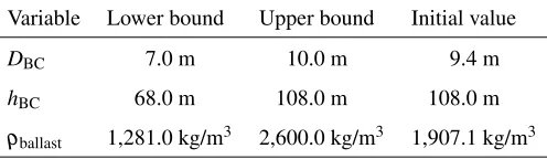
TABLE 3. DESIGN VARIABLES, THEIR VALUE RANGES, AND THEIR VALUES IN THE INITIAL FOWT SYSTEM MODEL.
Variable Lower bound Upper bound Initial value
DBC 7.0 m3/kg 10.0 m3/kg 9.4 m3/kg hBC 68.0 m3/kg 108.0 m3/kg 108.0 m3/kg
ρballast 1,281.0 kg/m3 2,600.0 kg/m3 1,907.1 kg/m3
The latter is defined through its densityρballastand filling height hballast within the bottom cylinder. As the ballast density is prescribed by available filling materials, it is selected as the third design variable, while the ballast height is not a direct design variable as it depends on the system parameters and chosen design variables and is determined internally to ensure floatation of the WT system. With regard to the structural parameters, only the diameter and height of the bottom cylinder are selected as design variables, whereas the original wall thickness remains unchanged, as the objective of the optimization is not the design strength but rather focuses on the hydrodynamic behavior of the FOWT system. Another component belonging to the floating spar-buoy structure is the mooring system. This, however, im-plying also the attachment points (fairleads), remains unchanged as the yaw stability is not analyzed explicitly in this study, but it would have to be considered as design variable as well, if the entire system stability is to be optimized.
For the three design variables, the allowable value ranges, as well as their values in the initial adjusted FOWT design are presented in Tab. 3. For the spar-buoy bottom cylinder diameter the lower limit is prescribed by the tower base diameter of the IWT-7.5-164, while the upper limit is inspired by the original value and chosen to be not significantly larger for the ease of handling and manufacturing. For the same reasons, the original bottom cylinder height is set as upper limit for this design variable, with an option to be reduced by up to 40.0 m. The potential ballast density values originate from the density ranges of cheap materials, such as sand with varying water content, rocks, or clay [13, 14]. Apart from the ballast type, which is con-ditional on available lower-cost material, the upper bounds for the geometric parameters are shaped by the author’s additional objective of limiting the outer dimensions of the floating system to facilitate the handling and manufacturing processes, but also to prevent a significant loss in the structural strength as this was excluded from the analysis. Different user-specific objectives and set value ranges would definitely affect the results. This is addressed again in the discussion at the end of the paper.
TABLE 4. OBJECTIVES OF THE OPTIMIZATION, THEIR
TAR-GET VALUES, AND THEIR CONSTRAINTS.
Objective parameter Target value2 Constraint
Inclination angle to the vertical [15–17]
10◦m2n ≤.6210◦m2n
Translational motion 0 m/s2 ≥.1620 m/s2
Horizontal nacelle ac-celeration3[15, 18, 19]
0.2g≈1.962 m/s2 ≤1.962 m/s2
2 A zero target value means that this objective parameter should be minimized
in general.
3 The allowable limit is given as factor of the gravitational acceleration
con-stantg≈9.81 m/s2.
Within the formulation for determining the ballast filling height as a function of the system mass and buoyancy mass (both are directly derived from the geometric parameters), it is checked thathballastnever becomes negative, nor exceedshBC. If the set-tings of the design variables would violate one of these con-straints, either the ballast density or floater material density is modified to overcome this issue. With having this defined within the MoWiT model, it is ensured that the ballast height remains within these boundaries during the entire optimization iterations.
3.2 Optimization Objectives
The objective of applying the direct optimization approach to the adapted OC3 spar-buoy carrying the IWT-7.5-164 WT is to obtain an appropriate floating support structure for the 7.5 MW WT, so that this FOWT system is stable and complies with general global performance criteria. This study neither focuses on the structural strength nor on the loading on the structure, such as fatigue due to system eigenfrequencies. These aspects, however, can be integrated by adding more optimization objectives, which are based on post-processed parameters and analyses.
Thus, focusing for the time being only on the global perfor-mance of the FOWT in operation, three objective functions are defined. These comprise the platform total inclination angle for stability and WT operational reasons, the translational motions due to motion restrictions of the power cable, and the nacelle acceleration because of sensitive components within the nacelle.
however, the optimization objectives have to be provided in terms of objective functions which are to be minimized, the three ob-jectives follow the expressions given in Eqn. 1 to Eqn. 3, respec-tively, normalizing the objectives for inclination (Eqn. 1) and ac-celeration (Eqn. 3) with respect to their target values.
|inclination−10◦|
10◦ (1)
translation (2)
acceleration−1.962
m s2
1.962m
s2
(3)
These objective functions are evaluated during the optimiza-tion for each considered design soluoptimiza-tion, substituting the objec-tives (inclination,translation, andacceleration) in each case by the maximum value obtained during the simulation. This is di-rectly derived by evaluating the resulting time series.
3.3 Design-Relevant Load Case
The iterative optimization procedure is carried out based on design-relevant load cases, used to simulate the considered float-ing system and to derive the performance criteria from the simu-lation results. For this first utilization of the direct optimization approach, only one design-relevant load case is selected based on DLC (design load case) simulations with the original OC3 spar-buoy FOWT system. From the recommended DLCs in the inter-national standard IEC 61400-3 [20], the following DLCs are se-lected for the simulation with the OC3 floating system, with hav-ing the optimization objectives, defined in Section 3.2, in mind:
• DLC 1.1 around rated wind speed(power production,
nor-mal turbulent wind model, nornor-mal sea state):
In normal power production around rated wind speed, the highest thrust force, and hence, a large inclination angle and large horizontal displacement are expected.
• DLC 1.3 below, at, and above rated wind speed(power
production, extreme turbulent wind model, normal sea state):
If the WT is sensitive to wind, hence at a wind dominated site, the extreme turbulent wind may yield extreme fluctua-tions and therefore large values for the nacelle acceleration.
• DLC 1.6a below, at, and above rated wind speed(power
production, normal turbulent wind model, severe sea state): If the WT is sensitive to waves, hence at a wave dominated
site, the severe sea state may yield extreme fluctuations and therefore large values for the nacelle acceleration.
• DLC 6.1b(parked condition, extreme steady wind model,
reduced wave height model, both with 50-year recurrence period):
In such an extreme event with 50-year recurrence period, the highest loads, implying a large inclination angle and a large horizontal displacement, are expected.
When running the DLC simulations, the OC3 FOWT system showed to be not designed properly for such an extreme environ-mental condition given in DLC 6.1b. As this is the only DLC from the four selected ones, in which the WT is not operating, there is no need to consider separate (less restrictive) objectives for a FOWT system in parked condition. Thus, for the evalua-tion, only the other three DLCs (1.1, 1.3, 1.6a) were used and it turned out that DLC 1.6a at rated wind speed and with a yaw misalignment angle of 8◦yields the highest values in the three objective parameters defined in Section 3.2. This environmen-tal condition is transferred to the IWT-7.5-164 FOWT system, assuming similar system behavior, and used for the simulations within the direct optimization approach.
3.4 Optimization Settings
From a broad range of algorithms and optimization pro-cedures, of which some are presented in [11], the evolutionary algorithm NSGAII (non-dominated sorting genetic algorithm II) from Platypus [21] is selected to be used in this study. The reasons for this choice are, first of all, the demands from the system model and optimization task under consideration. Due to the complexity of a FOWT system, gradient-based optimizers would not be suitable as the system equations cannot be reduced to just one single equation. Furthermore, the three explicitly defined objective functions, outlined in Section 3.2, recommend the utilization of a multi-objective optimizer. Secondly, taking into account these demands, three common stateoftheart gradientfree multiobjective optimizers [22] -NSGAII, NSGAIII (non-dominated sorting genetic algorithm III), and SPEA2 (strength Pareto evolutionary algorithm) -are tested, using the open-source framework Platypus [21]. The comparison showed that NSGAII more accurately meets the constraints and objectives, better than NSGAIII, but is at the same time, compared to SPEA2, faster converging to an optimum solution.
gener-ation and the total number of simulgener-ations to be run is defined as 1080, which would correspond to 30 generations (29 plus the start population with number 0)4. A comprehensive sensitivity analysis for justifying the selected population size and number of generations was not yet covered in this study. However, based on the convergence behavior, discussed in Section 4.1, the cho-sen settings proved to provide satisfactory results.
RESULTS
The results of the direct optimization approach, applied to the initially adapted OC3 spar-buoy with the IWT-7.5-164 on top, are presented in the following, first, showing the results throughout the optimization process, and then focusing on the final floater design, which is obtained from the direct optimiza-tion approach to be proper for supporting the IWT-7.5-164.
4.1 Development Throughout the Optimization Itera-tions
Within the direct optimization procedure, finally, 1097 individuals are created, simulated, and evaluated. The number differs slightly from the specified number of total simulations of 1080, as defined in Section 3.4, due to the internal management of running simulations in parallel. This way, individuals from generation 0 up to generation 31 are created, while the last full generation, meaning containing all 36 individuals, is generation number 264.
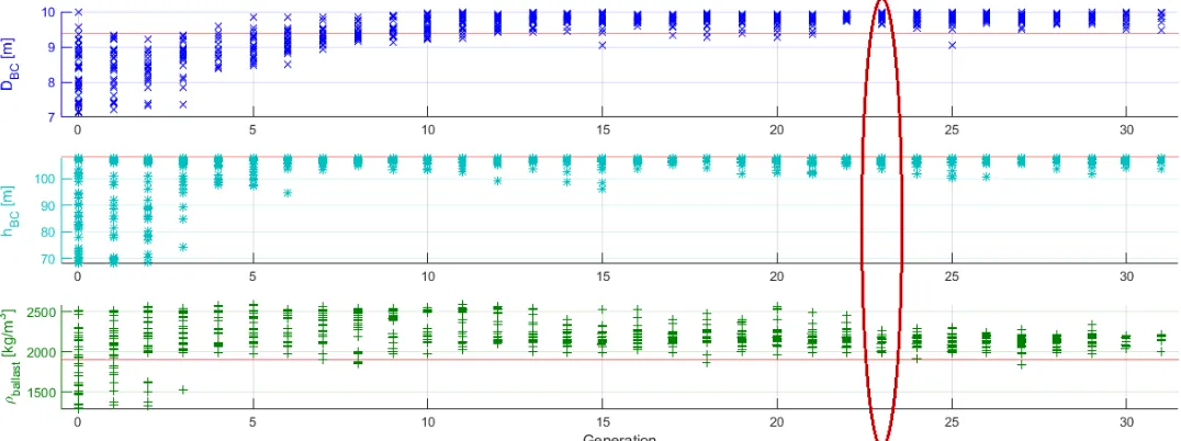
Within each generation, the design variables for the individ-uals are chosen by the optimizer from the specified value ranges, based on the objectives obtained from the previously simulated individuals. Hence, a trend from a broad spread of selected val-ues for the design variables towards more and more optimum values is clearly visible throughout the optimization procedure, as visualized in Fig. 4(a). The corresponding trend in the ob-tained optimization objectives (Fig. 4(b)) shows as well decreas-ing spreads and, what is most important, an improvement with respect to the objectives set. In Fig. 4(b), it is noticeable that in the first few generations not for all 36 individuals an objec-tive value is plotted. The reason for this is that, at the start of the optimization procedure, individuals from the entire allowable value ranges for the design variables are created. These, however, do not all perform that well and some might be instable, which causes an early termination of the simulation. The effectively simulated time is taken as criterion for identifying unsuccessful simulations, which are then assigned undesirable objectives to ensure exclusion of these designs [11, 12].
4Note: The counting of generations starts with number 0 for the start
popula-tion.
4.2 Spar-Buoy Design for the IWT-7.5-164
From the 1097 individuals, obtained within the direct opti-mization approach, the optimum and final appropriate spar-buoy floater design for the IWT-7.5-164 WT has to be found. The method and criteria for the selection of the optimum geometry are described firstly, and then the obtained FOWT system is pre-sented and analyzed.
4.2.1 Selection of the Floater Design As the specified stop criterion, defined through the total number of simulations, which corresponds approximately to a maximum number of generation, is set quite arbitrary, first, the generation has to be determined at which the optimization algorithm has converged before it starts diverging again. To do so, two selection options are considered: based on the minimum spread of the design variables or based on the minimum spread of the objectives. The first option would yield generation 23, the latter generation 22 to be considered for determining the optimum individual, as highlighted in Fig. 4(a) and Fig. 4(b) in dark red, respectively. As the point of interest in this study is the convergence of the optimization to one optimum design, the first selection method, based on the minimum spread of the design variables, is used, and hence generation 23 is taken for finding the best individual in it.
For the selection of the optimum individual, first, the min-imum value for each of the three objectives is identified, com-paring all individuals within generation 23. These three values, which originate from different individuals in generation 23, are used as utopia for the objectives. Then, for each individual in generation 23, the distance of its objectives to the utopia point is determined by means of the root of the sum of the three individ-ual distances squared. Here, it has to be noted that the distances for the inclination and acceleration objectives are calculated di-rectly, as these objectives are already normalized, as indicated in Eqn. 1 and Eqn. 3, respectively, while the distance for the trans-lation objective, which is by definition (see Eqn. 2) just directly the translation value, is now normalized with respect to the utopia value for the translation. Doing so, the individual within gener-ation 23, which yields the minimum distance of its objectives to the utopia point, is determined to be the optimum solution.
(a) DEVELOPMENT OF THE DESIGN VARIABLES IN COMPARISON TO THE INITIAL VALUES (RED LINES).
[image:8.612.38.576.76.277.2](b) DEVELOPMENT OF THE OPTIMIZATION OBJECTIVES.
FIGURE 4. SELECTED INDIVIDUALS THROUGHOUT THE SIMULATED GENERATIONS IN THE DIRECT OPTIMIZATION APPROACH,
THE GENERATION SELECTED BASED ON THE FIRST AND USED APPROACH (THICK LINE) OR THE SECOND SELECTION OPTION (THIN LINE) IS CIRCLED IN DARK RED.
direct optimization approach, and the final optimized spar-buoy geometry for the IWT-7.5-164 WT, is shown in Fig. 5.
Due to the fact that two potential methods have been initially considered for the selection of the generation, at which the op-timization has converged, as mentioned in Subsection 4.2.1, the results obtained when using the second alternative based on the minimum spread of the objectives (yielding generation 22) are determined as well and compared in Tab. 6 to the final results
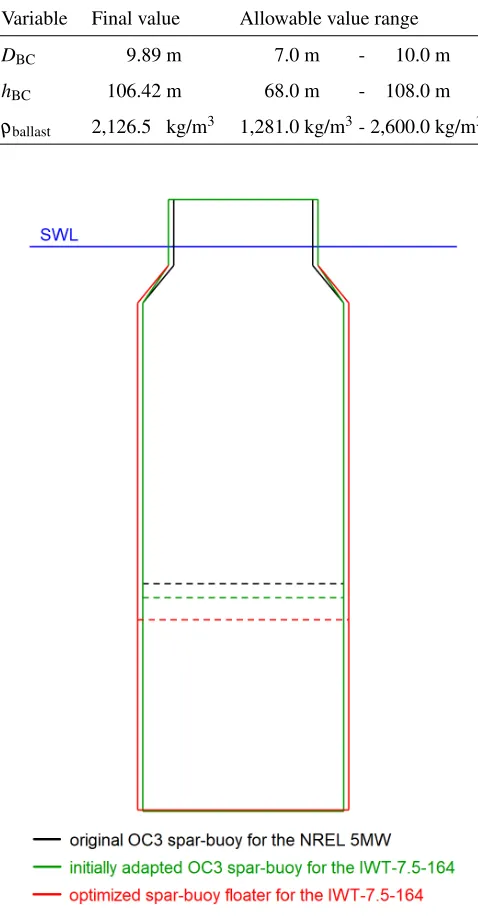
TABLE 5. FINAL VALUES OF THE DESIGN VARIABLES AND THEIR SPECIFIED VALUE RANGES.
Variable Final value Allowable value range
DBC 9.89 m3/kg 7.0 m3/kg-2,610.0 m3/kg hBC 106.42 m3/kg 68.0 m3/kg-2,108.0 m3/kg
ρballast 2,126.50kg/m3 1,281.0 kg/m3- 2,600.0 kg/m3
FIGURE 5. ORIGINAL, INITIALLY ADAPTED, AND FINAL
OP-TIMUM SPAR-BUOY FLOATER GEOMETRIES IN COMPARISON, DASHED LINES INDICATING THE BALLAST HEIGHT.
4.2.3 Performance of the 7.5 MW FOWT System To prove the suitability of the obtained final spar-buoy geometry, the performance of the FOWT system, consisting of the IWT-7.5-164 WT and the optimum floater design, outlined in Subsec-tion 4.2.2, is analyzed. This means that the considered
design-TABLE 6. COMPARISON OF THE RESULTS FOR THE
OPTI-MUM SPAR-BUOY FLOATER GEOMETRY FOR THE TWO GEN-ERATION SELECTION METHODS.
Variable Generation 23 Generation 22
DBC 9.89 m3/kg 9.88 m3/kg
hBC 106.42 m3/kg 106.42 m3/kg
ρballast 2,126.50kg/m3 2,114.40kg/m3
[image:9.612.43.282.120.580.2]Distance to utopia point 0.0218kg/m3 0.0254kg/m3
TABLE 7. PERFORMANCE OF THE FINAL DESIGN WITH
RE-SPECT TO THE DEFINED OPTIMIZATION OBJECTIVES.
Objective param-eter
Maximum Target Constraint
Inclination 9.86◦m2n 10◦m2n ≤.6210◦m2n Translation 42.92 m/s2 0 m/s2 ≥.1620 m/s2 Acceleration 1.929 m/s2 1.962 m/s2 ≤1.962 m/s2
relevant load case, according to the definition in Section 3.3, is simulated with the obtained 7.5 MW FOWT system and the max-imum value for each of the defined optimization objective, spec-ified in Section 3.2, is taken from the output time series. The results are presented in Tab. 7 and it can clearly be seen that all constraints are met, while still the objective parameters are close to the target values.
DISCUSSION
By means of the presented direct optimization approach, a floating support structure design for a larger WT is obtained based on a smaller existing FOWT system. The finally achieved design is based on the specified design conditions, as described in Sections 3.1 to 3.4, and also highly dependent on their settings. Hence, different choices will yield different designs, each optimum for the specific design conditions considered.
[image:9.612.320.576.296.379.2]checks the requirement of having the system natural frequencies far from the wave spectra peak frequencies by minimizing the system response, but can also easily be extended by adding more detailed checks, as well as further criteria and optimization objectives, such as for the structural strength or loads and fatigue. Furthermore, a more sophisticated design optimization, implying the design strength but also, for instance, the mooring system, would as well require the definition of additional design variables, such as the wall thickness, the fairlead and anchor positions, the mooring line length, and its extensional stiffness.
In general, the settings have to be selected carefully to en-sure that the direct optimization approach can be successful. When still intending an upscaling to a larger MW-class WT, this has to be taken into account in the definition of the boundaries for the allowable value ranges of the design variables, to allow for obtaining a stable FOWT system in the end. Furthermore, there is large freedom in the selection of design variables, both with respect to the variable itself and the number of variables. The optimization objectives will definitely also influence the fi-nal optimum design. The objectives selected in this study can be considered as general parameters for the global performance of a FOWT system; however, for more detailed assessment and design of a FOWT system there are almost no limits to the objec-tives. But still this has to be treated with caution, as this is always subject to a cost-benefit calculation. This aspect was also the rea-son for just selecting one design-relevant load case, which is then used during the direct optimization approach, instead of running an entire DLC set in each iteration with all individuals. But still it needs to be proved that the obtained optimum FOWT system de-sign performs as required in various environmental conditions. Finally, the achieved optimum design will also depend on the optimization settings; however, due to the preceding study and comparison, it is expected that the selected optimizer NSGAII is suitable for the presented application. The number of simula-tions to be run is of course again a trade-off between cost or time and benefit and the user has to define up to which accuracy and convergence tolerance the optimization has to be performed. In the end, the final selection of the optimum design out of the huge number of created and simulated individuals depends again on the point of interest and selected approach. However, as shown in Subsection 4.2.2, the resulting optimum designs differ not sig-nificantly if the methods are reasonable and the optimization al-gorithm has run sufficiently long so that a convergence is clearly visible.
CONCLUSION
In this paper, a direct optimization approach is presented, by which means a floating support structure for a larger MW-class WT is obtained based on an existing smaller FOWT sys-tem design without using the intermediate step of upscaling.
This approach is developed in Python programming language. A Python-Modelica framework allows interfacing with FOWT system models defined in the MoWiT library, execution of sim-ulations in Dymola, and programming, as well as utilization of optimization procedures in Python. The input to this direct opti-mization algorithm only requires minor initial adaptions of the original FOWT system model, as well as the specification of the design conditions, such as the design variables which are to be modified during the optimization, the optimization objectives which should be focused on, the environmental conditions which are used for the system simulation, as well as the optimization settings. Even if the final result highly depends on the choice for these design conditions, an appropriate FOWT system design, which fulfills the specified requirements and performs well with respect to the defined objectives, can be obtained automatically by means of this direct optimization approach.
ACKNOWLEDGMENTS
This work was partially supported by grant EP/L016303/1 for Cranfield University, University of Oxford and University of Strathclyde, Centre for Doctoral Training in Renewable Energy Marine Structures - REMS (http://www.rems-cdt.ac.uk/) from the UK Engineering and Physical Sciences Research Council (EPSRC).
REFERENCES
[1] Leimeister, M., 2016. “Rational Upscaling and Modelling of a Semi-Submersible Floating Offshore Wind Turbine”. Master Thesis, Delft University of Technology and Norwe-gian University of Science and Technology and Fraunhofer Institute for Wind Energy Systems.
[2] Jonkman, J., and Musial, W., 2010.Offshore Code Compar-ison Collaboration (OC3) for IEA Task 23 Offshore Wind Technology and Deployment: Technical Report NREL/TP-5000-48191. Technical Report. U.S. Department of Energy. [3] Popko, W., Thomas, P., Sevinc, A., Rosemeier, M., B¨atge, M., Braun, R., Meng, F., Horte, D., Balzani, C., Bleich, O., Daniele, E., Stoevesandt, B., Wentingmann, M., Polman, J. D., Leimeister, M., Sch¨umann, B., and Reuter, A., 2018. IWES Wind Turbine IWT-7.5-164 Rev 4. Fraunhofer Insti-tute for Wind Energy Systems IWES, Bremerhaven. [4] Jonkman, J., Butterfield, S., Musial, W., and Scott,
G., 2009. Definition of a 5-MW Reference Wind Tur-bine for Offshore System Development: Technical Report NREL/TP-500-38060. Technical Report. U.S. Department of Energy.
Confer-ence Proceedings, Link¨oping University Electronic Press, pp. 633–642.
[6] Thomas, P., Gu, X., Samlaus, R., Hillmann, C., and Wihlfahrt, U., 2014. “The OneWind Modelica Library for Wind Turbine Simulation with Flexible Structure -Modal Reduction Method in Modelica”. In 10th Interna-tional Modelica Conference, Link¨oping Electronic Confer-ence Proceedings, Link¨oping University Electronic Press, pp. 939–948.
[7] Strobel, M., Vorpahl, F., Hillmann, C., Gu, X., Zuga, A., and Wihlfahrt, U., 2011. “The OnWind Modelica Li-brary for Offshore Wind Turbines - Implementation and first results”. In 8th International Modelica Conference, Link¨oping Electronic Conference Proceedings, Link¨oping University Electronic Press, pp. 603–609.
[8] Leimeister, M., Kolios, A., Collu, M., and Thomas, P., 2019. “Development and Verification of the OC3 Phase IV Floating Spar-Buoy Wind Turbine System, Utilizing Fraun-hofer’s MoWiT Library: (to be published)”.
[9] Jonkman, J., 2010. Definition of the Floating System for Phase IV of OC3: Technical Report NREL/TP-500-47535. Technical Report. U.S. Department of Energy.
[10] Hansen, M. H., Hansen, A., Larsen, T. J., Øye, S., Sørensen, P., and Fuglsang, P., 2005. Control design for a pitch-regulated, variable speed wind turbine, Vol. 1500 ofRisø R, Report. Risø National Laboratory, Roskilde. [11] Leimeister, M., Kolios, A., Collu, M., and Thomas, P.,
2019. “Development of a Framework for Wind Turbine Design and Optimization: (to be published)”.
[12] Leimeister, M., 2019. “Python-Modelica Framework for Automated Simulation and Optimization”. In 13th Interna-tional Modelica Conference, Link¨oping Electronic Confer-ence Proceedings, Link¨oping University Electronic Press, pp. 51–58.
[13] Engineering ToolBox, 2010. Densities of Common Materials: [online] Available at: https://www.engineeringtoolbox.com/density-materials-d 1652.html [Accessehttps://www.engineeringtoolbox.com/density-materials-d: 12 December 2018].
[14] Engineering ToolBox, 2009. Densi-ties of Solids: [online] Available at: https://www.engineeringtoolbox.com/density-solids-d 1265.html [Accessehttps://www.engineeringtoolbox.com/density-solids-d: 12 December 2018].
[15] Huijs, F., Mikx, J., Savenije, F., and de Ridder, E.-J., 2013. “Integrated design of floater, mooring and control system for a semi-submersible floating wind turbine”. In EWEA Offshore, European Wind Energy Association.
[16] Kolios, A., Borg, M., and Hanak, D., 2015. “Reliability analysis of complex limit states of floating wind turbines”. JECM, 2(1), pp. 6–9.
[17] Katsouris, G., and Marina, A., 2016. Cost Modelling of Floating Wind Farms: ECN-E–15- 078. ECN Report. ECN, Petten, The Netherlands.
[18] Nejad, A. R., Bachynski, E. E., and Moan, T., 2017. “On Tower Top Axial Acceleration and Drivetrain Responses in a Spar-Type Floating Wind Turbine: OMAE2017-62314”. In ASME 2017 36th International Conference on Ocean, Offshore and Arctic Engineering, OMAE 2017, The Amer-ican Society of Mechanical Engineers, p. V009T12A009. [19] Suzuki, K., Yamaguchi, H., Akase, M., Imakita, A.,
Ishi-hara, T., Fukumoto, Y., and Oyama, T., 2011. “Initial De-sign of Tension Leg Platform for Offshore Wind Farm”. JFST, 6(3), pp. 372–381.
[20] International Electrotechnical Commission, 2009. Wind turbines – Part 3: Design requirements for offshore wind turbines: IEC 61400-3, 1 ed. International Standard. [21] Hadka, D., 2015. Platypus Documentation: Release. [22] Mytilinou, V., and Kolios, A. J., 2017. “A multi-objective
![FIGURE 1.THE OC3 SPAR-BUOY FOWT SYSTEM [2].FIGURE 2.PARAMETERS OFTHE OC3 SPAR-BUOY.](https://thumb-us.123doks.com/thumbv2/123dok_us/1343229.88031/2.612.319.569.69.281/figure-spar-buoy-fowt-figure-parameters-ofthe-spar.webp)
![FIGURE 3.THE OC3 FOWT SYSTEM MODELLED IN MoWiTAND SIMULATED IN DYMOLA [5].](https://thumb-us.123doks.com/thumbv2/123dok_us/1343229.88031/3.612.40.290.100.335/figure-oc-fowt-modelled-mowitand-simulated-dymola.webp)