Abstract— A high-temperature superconducting (HTS)
terahertz (THz) heterodyne mixer based on a thin-film antenna - coupled YBa2Cu3O7-x (YBCO) step-edge Josephson junction is
presented. The frequency down-conversion from 0.6 THz to an intermediate frequency (IF) of 2 GHz was achieved using high-order harmonic mixing of a local oscillator (LO), thus removing the need to use a second THz source as the LO pumping source. The DC and RF characteristics of the harmonic mixer as well as the relationship of the IF output power versus the harmonic number were experimentally studied and compared with simulated results. Most of our measurements were made at 40K, but we also observed stable harmonic mixing at 77K which we believe has not been reported previously in HTS junction mixers.
Index Terms— High-temperature superconductor, Josephson
mixer, terahertz mixer, harmonic mixing, simulation.
I. INTRODUCTION
requency down-conversion at submillimeter and terahertz (THz) frequency bands is difficult to implement owing to the lack of high performance and low-cost components and modules. The frequencies are too high for conventional electronics and too low for conventional optical technologies. The extensive transmission loss in the atmosphere of submillimeter and THz waves requires an ultrasensitive heterodyne receiver for the detection of the weak THz signals. The performance of a heterodyne receiver critically depends on its frontend components, the frequency down-converter or mixer in particular. High-temperature superconducting (HTS) Josephson junctions are attractive candidates due to their superior sensitivity, large bandwidth, high frequency operation (well into the THz band) and low local oscillator (LO) power
requirement. Compared to their low-temperature
superconducting (LTS) counterparts, the HTS devices can operate at relatively higher temperatures reducing the cost and
Jia Du is with CSIRO Manufacturing, Lindfield, NSW 2070, Australia (e-mail: [email protected]).
Colin Pegrum is with the Department of Physics, University of Strathclyde, Glasgow G4 0NG, UK (e-mail: [email protected]).
Xiang Gao is with CSIRO Manufacturing, Lindfield, NSW 2070, Australia (e-mail: [email protected]).
Andrew R. Weily is with CSIRO Data61, Marsfield, NSW 1710, Australia (e-mail: [email protected]).
Ting Zhang is with CSIRO Data61, Marsfield, NSW 1710, Australia (e-mail: [email protected]).
Yingjie J. Guo is with University of Technology Sydney, NSW 2007, Australia (e-mail: [email protected]).
Cathy. P. Foley is with CSIRO Manufacturing, Lindfield, NSW 2070, Australia (e-mail: [email protected]).
The simulation work of C. M. Pegrum done at CSIRO was supported by their Distinguished Visiting Researchers Scheme.
complexity of the cryogenic instrument. A smaller and cheaper electronic powered cryocooler may be used to cool the devices.
HTS Josephson junction mixers have been demonstrated in microwave and millimeter frequencies with competitive performance [1-7]. There are, however, very limited reports of successful demonstration of HTS Josephson junction mixers in THz frequency bands [8-10], of which they usually operated at the temperatures below 77 K and at frequencies lower than that reported in this paper. Harmonic mixing has been observed in HTS junctions at millimeter [6, 7] and THz frequency ranges [10] but little information on the mixer performance was given. The HTS Josephson junction-based active devices are far less developed than their LTS counterparts due to the relatively challenging HTS grain-boundary Josephson junction technologies. CSIRO has in the past decade developed and continuously improved the step-edge technology [11, 12]. High performance heterodyne mixers based on the HTS step-edge technology have been developed in the microwave frequency range up to 30 GHz [1-4].
In this paper, we report the successful demonstration of a HTS step-edge junction heterodyne mixer at 0.6 THz using 18 to 31 order harmonic mixing. The mixer IF output is studied as a function of the harmonic number. Simulation of the HTS Josephson harmonic mixer was also carried and compared with that of the experimental results.
II. EXPERIMENTAL DETAILS
Fig. 1. Photographs of the fabricated device chip – Au thin-film ring-slot antenna coupled HTS step-edge junction THz mixer. The right-hand image shows an enlarged view of the step-edge Josephson junction.
The packaged HTS Josephson junction 0.6 THz mixer module was cooled in a commercial 2-stage pulse-tube cryocooler and was characterized at operating temperatures between 40 and 77K, a temperature range that can also be obtained using a single-stage mini cryocooler. A solid-state THz source (VDI 625 GHz Amplifier Multiplier Chain) was used to generate continuous wave radiation between 590 and 650 GHz. The THz signal, after passing through a pair of collimating and focusing mirrors, was coupled into the HTS mixer module via the Si lens through the cryocooler window. The LO pumping signal was generated using a Wiltron 68075B microwave generator. The LO and IF signals shared the same port on the mixer module, and a microwave diplexer was used to realize the isolation between them. The mixer IF output was amplified using a room-temperature low-noise-amplifier (LNA) and recorded by an Agilent E4407B spectrum analyzer. A battery-powered DC current source was used to bias the Josephson mixer.
III. EXPERIMENTAL RESULTS AND DISCUSSION
The frequency down-conversion characterization was achieved using a harmonic mixing operation. The advantage of the scheme is that a second THz source for the LO pumping is not needed, thus reducing the cost and complexity of the system. The mixer operated stably at the temperatures up to 77K although the selected results at 40K (except for Fig. 3b) are given in this paper to show the relationship of the mixing performance versus the harmonic order number.
Fig. 2 shows the mixer DC current-voltage characteristics (IVCs) under the illumination of a 614.4 GHz signal (a) and pumped with a 20.4 GHz LO signal (b), respectively. The unpumped step-edge junction exhibits a critical current Ic
500 μA (at T = 40 K) and a normal resistance Rn 4 . This
corresponds to a characteristic voltage, Vc ≡ IcRn 2 mV and a
characteristic frequency, fJ ≡ IcRn/0 (where 0 is the
magnetic flux quantum, 1/0 ≡ 2e/h = 0.4836 GHz/V), of ~ 1
THz. These values show that our step-edge junction is well suited for the THz frequency down-converter. Fig. 2(a) shows that the THz signal frequency fTHz = 614.4 GHz induced clear
Shapiro-steps at the voltages Vn = n0fTHz = n × (1.27 mV) (n
[image:2.612.333.555.51.353.2]= …, -2, -1, 0, 1, 2, ...) as predicted by the AC Josephson effect. The Shapiro current step-heights depend on the effective THz power coupled into the junction. Fig. 2(b) is the
Fig. 2. DC IVCs under (a) the illumination of a 614.4 GHz signal and (b) LO pumping (at fundamental frequency) at T = 40K.
(a)
(b)
Fig. 3. Examples of the down-converted IF frequency spectra: (a) 20th harmonic mixing (fIF = 614.4 GHz – 20×30.6 GHz = 2.4 GHz) at 40K; and (b)
[image:2.612.46.301.56.163.2] [image:2.612.349.525.384.695.2]is the 31st harmonic mixing result, i.e. fIF = 614.4GHz –
31×19.75 GHz = 2.15 GHz, at T = 77K. The fact that our harmonic mixer was able to operate at 77 K reliably indicates the excellent quality of our step-edge junction coupled with a well-designed THz antenna and matching microwave circuit. To the best of our knowledge, the HTS Josephson junction sub-millimeter and THz mixers reported in the literature were only operated at temperatures below 77 K.
[image:3.612.315.566.132.296.2]
Fig. 4. Experimental result of IF output versus bias current IB at fixed RF and
LO power.
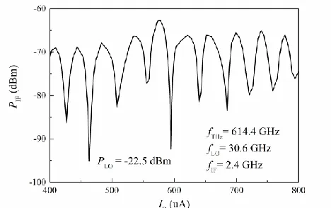
Fig. 4 shows the measured relationship between the mixer IF output power PIF at 2.4 GHz and the bias current IB for the
20th order harmonic mixing between a 30.6 GHz (fundamental
frequency) LO signal and a THz signal of 614.4 GHz. The mixer works at a wide range of current bias conditions and PIF
displays strong modulation due to the LO-pumping induced Shapiro steps. Furthermore, it is found that the minima of PIF
are not at every Shapiro step. The simulation results in Section IV also confirm a similar behavior.
The IF output power of harmonic mixing as a function of the harmonic number was experimentally studied and plotted in Fig. 5. The harmonic number studied ranges from 18 to 31 corresponding to the fundamental LO frequencies between 34 to 19.74 GHz which was limited by the diplexer frequency range. The IF frequency was kept around 2.4 GHz. The bias current was similar and the LO power was adjusted to yield the first IF maximum. The IF output and the mixer conversion efficiency decrease with the increase of harmonic order. It was noticed that the odd-order harmonic mixing yields lower IF output (marked 21 and 31 in the graph) and the PIF decreases
more rapidly as the harmonic number increases compared with that of the even-order harmonic mixing. Fitting of the experimental data points for the even-order harmonic mixing yielded the relationship PIF (mW) N-3.1. The scaling factor
Fig. 5. Experimental result of IF output power versus the harmonic number.
IV. SIMULATION OF THE HTS HARMONIC MIXER
To support the experimental results, the harmonic mixer was simulated using JSIM [14] and the methods are set out in [15], based on a resistively-shunted junction (RSJ), with Ic = 500 A, Rn =3.8. The junction capacitance CJ was
estimated as 18fF from [16] and its hysteresis parameter βC
= 2πIcRn2CJ/0 = 0.4, so it is non-hysteretic. Simulations
were run for a temperature T = 40 K. Current sources supplied DC bias IB, also LO and THz pumping with
amplitudes ILO and ITHz respectively.
DC IVCs were derived for a wide range of ILO and ITHz.
A typical set of IVCs pumped by a 614.4 GHz signal is shown in Fig. 6. These agree quantitatively with our experimental data (Fig. 2a) and confirm the validity of the simulation model.
Fig. 7 is the simulated IF power PIF as a function of DC
bias current IB for fixed levels of THz and LO currents.
These results were obtained from the JSIM time-varying output voltage using Octave to derive the Power Spectral Density and a routine to locate and measure the power of the IF peak [15]. Again, there is broad agreement with the experimental data (Fig. 4), with minima in IF output occurring on steps induced by the LO frequency, though in the example we show here the operating conditions are not the same. For simulation (but less so for experiment) it is easy to plot this data as a function of voltage, rather than bias current. From such plots (not shown here) we find that PIF minima do occur at integer multiples or harmonics of
fLO, but not at every value. The corresponding harmonics of
fLO are identified by the numbers (red) in Fig. 7. Also the
simulated data was sampled at smaller intervals of bias current than the experimental data and shows some extra structure between minima. This, and the PIF dependence is
[image:3.612.60.294.258.405.2]Fig. 6. Simulated DC IVCs with differing amplitudes of 614.4 GHz RF current ITHz, all with ILO = 0.
[image:4.612.62.288.63.220.2]
Fig. 7. Simulated IF power as a function of bias current, at fixed THz and LO current drive. In this example fTHz= 614.4 GHz and fLO =19.75 GHz
which is multiplied by harmonic number N = 31, so that fIF = 2.15 GHz.
Each number in red indicates the order of the Shapiro step at which a minimum is found, equal to fJ /fLO=V/(Φ0 fLO), where fJ is the Josephson
frequency.
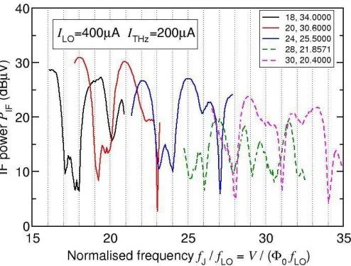
We have also used our simulation methods to look at the dependence of PIF on harmonic number N. For this we
chose a fixed IF frequency of 2.4 GHz and 614.4 GHz for fTHz, and used the same range for N as we did for the
experimental data shown in Fig. 5 in the last section (though only for even harmonic numbers). We ran simulations for a limited range of bias current (500 – 600 A) for each N value. The simulation results for the five harmonic numbers measured (Fig. 5) are collected together in Fig. 7. Here we have extracted the average voltage V for each data point, and we plot PIF versus fJ /fLO so again we expect
minima in PIF to lie on integer values of this quantity.
Changing N and therefore fLO causes the shape of the IVC to
change and, at fixed bias, V moves upwards as N increases, so that each sub-plot for each value of N within. Fig. 8 moves up with rising normalized frequency. It is apparent that the minima do align with integer values, though as noted before, not on every integer value. Also, there is in
general a decrease in PIF as N increases. These findings are
broadly consistent with our experimental measurements shown in Fig. 5.
[image:4.612.317.564.146.333.2]In summary, for simulations, the current-source driven RSJ model works well with JSIM and provides a powerful tool for investigating and predicting the properties and performance of the THz harmonic mixer.
Fig. 8 Simulated PIF as a function of the average voltage V, where V has been
expressed in terms of the Josephson frequency fJ =V/Φ0, and then normalized
to the LO frequency fLO. The legend box lists values of N, and the
corresponding values of fLO in GHz, for each of the sub-plots.
V. CONCLUSIONS
A thin-film ring-slot antenna coupled YBCO step-edge Josephson junction heterodyne THz mixer is presented. High-order (up to 31st) harmonic mixing of a signal 0.6 THz to a
down-converted IF frequency of ~ 2 GHz is studied at 40K although the HTS mixer operated well at temperatures up to 77 K. The DC and RF characteristics of the THz mixer are presented and compared with some simulated results. The harmonic mixer has been simulated using JSIM based on RSJ model. Good qualitative agreement between the experiment and simulated results is obtained. The IF output power decreases with increasing the harmonic order number N in an experimental relationship PIF N-3.1 for the even-order
harmonic number. The odd-order harmonic number mixing appeared to yield noticeably lower IF output power. The new HTS Josephson heterodyne mixer can be potentially applied to THz sensing and communication receiver front-end systems.
ACKNOWLEDGMENT
[image:4.612.63.294.264.445.2]converter”, Supercond. Sci. Technol. 27 105002, 2014.
[4] T. Zhang, J. Du, Y. J. Guo, X. W. Sun, “A high-performance MMIC HTS Josephson mixer”, IEEE Trans Microwave and Wireless Components Lett., 23, no. 8, pp. 427-429, 2013.
[5] O. Harnack, M. Darula, J. Scherbel, J.-K. Heinsohn, M. Siegel, D. Diehl, and P. Zimmermann, “Optimization of a 115 GHz waveguide mixer based on an HTS Josephson junction,” Supercond. Sci. Technol., vol. 12, no. 11, pp. 847-849, Nov. 1999.
[6] Y. Fukumoto, I, Shigaki, H. Kajikawa, R. Ogawa and Y. Kawate, “Detection of 110 GHz millimeter-wave signal using DyBaCuO step-edge junction”, IEEE Trans. Appl. Supercond., vol.3, no. 1, pp. 2238-2241, Mar. 1993.
[7] Y. Fukumoto, R. Ogawa and Y. Kawate, “Millimeter-wave detection by YBCO step-edge microbridge Josephson junction”, J. Appl. Phys. vol. 74, no. 5, pp. 3567-3571, Sept 1993.
[8] J. Scherbel, M. Darula, O. Harnack, and M. Siegel, “Noise properties of HTS Josephson mixers at 345 GHz and operating temperatures at 20 K,” IEEE Trans. Appl. Supercond., vol. 12, no. 2, pp. 1828-1831, Jun. 2002. [9] M. Malnou, C. Feuillet-Palma, C. Ulysse, G. Faini, P. Febvre, M. Sirena,
L. Olanier, J. Lesueur, and N. Bergeal, “High-Tc superconducting Josephson mixers for terahertz heterodyne detection,” J. Appl. Phys., vol. 116, no. 7, pp. 074505-11, Aug. 2014.
[10] J. Chen, H. Myoren, K. Nakajima, T. Yamashita, “THz mixing properties of YBa2Cu3O7- grain boundary Josephson junctions on bicrystal substrates”, Physica C, vol. 293, pp. 288-291, 1997.
[11] C. P. Foley, E. E. Mitchell, S. K. H. Lam, B. Sankrithyan, Y. M. Wilson, D. L. Tilbrook and S. J. Morris, “Fabrication and characterisation of YBCO single grain boundary step-edge junctions”, IEEE Trans. Appl. Supercond. 9, pp. 4281-4284, 1999.
[12] E. E. Mitchell and C. P. Foley, “YBCO Step-edge junctions with high IcRn”, Supercond. Sci. Technol., vol. 23, 065007, 2010.
[13] S. Kita and K. Fujisawa, “Performance of Josephson junction harmonic mixers with harmonic numbers 1-8 at 70 GHz”, Japn J. Appl Phys., vol. 21, no. 3, pp. 497-503, Mar 1982.
[14] J. Satchell, “Stochastic simulation of SFQ logic,” IEEE Trans. Appl. Supercond., vol. 2, no. 7, pp. 3315 – 3318, Jun. 1997.
[15] C. Pegrum, T. Zhang, J. Du and Y. J. Guo, “Simulation of HTS Josephson mixers”, IEEE Trans. Appl. Supercond., vol. 26, no. 3, Art. No. 1500905, Apr. 2016.