UNIVERSITI TEKNIKAL MALAYSIA MELAKA
BEKU 4894
FINAL YEAR PROJECT
TITLE: INTERIOR PERMANENT MAGNET SYNCHRONOUS MOTOR DRIVES
NAMES & MATRIC NO. MUHAMMAD AZRIN BIN HASHIM B011110138
CLASS 4 BEKE
DATE OF SUBMISSION 5TH JUNE 2015
PANEL’S NAME
PANEL 1: DR AUZANI BIN JIDIN
PANEL 2: SYAHAR AZALIA BINTI AB. SHUKOR
INTERIOR PERMANENT MAGNET SYNCHRONOUS MOTOR DRIVES
MUHAMMAD AZRIN BIN HASHIM
This Report submitted in partial fulfillment of requirement for the degree of bachelor in
Electrical Engineering Power Electronic and Drives with Honours
Faculty of Electrical Engineering
UNIVERSITI TEKNIKAL MALAYSIA MELAKA
i
ACKNOWLEDGEMENT
ii
ABSTRACT
iii
ABSTRAK
v
TABLE OF CONTENTS
ABSTRACT ii
ACKNOWLEDGMENT iv
LIST OF FIGURES vii
LIST OF SYMBOLS ix
LIST OF TABLES xi
CHAPTER 1 1
1.1. Research Background 1
1.2. Problem Statement 2
1.3. Objectives 3
1.4. Scope of Project 4
1.5. Expected Outcomes 4
1.6. Report Outline 4
CHAPTER 2 6
2.1. Introduction 6
2.2. Mathematical Equation of IPMSM 9
2.2.1. Torque Control Equation Te for IPMSM 9
2.2.2. Current Vector Control with Maximum Torque/Ampere 11
2.2.3. Vector Control 13
2.3. Review of Previous Work 17
2.4. Summary and Discussion of the Review 22
CHAPTER 3 23
3.1. Introduction 23
3.2. Flowchart 24
3.3. Modeling 25
vi
3.3.2. Maximum Torque per Ampere Control 28
3.3.3. Flux-weakening Mode Speed Controller 31
3.3.4. Voltage Source Inverter (VSI) 33
3.3.5. Control Scheme of IPMSM 35
3.3.6. PI Controller 37
3.3.7. Dynamic model of IPMSM 38
3.4. Analytical of Simulation Approach 39
3.4.1. Hysteresis Current Controller 39
3.5. Project Gantt Chart and key milestones 41
CHAPTER 4 44
4.1. Progress of the report 44
4.1.1. Switching Pulses 44
4.1.2. Output Inverter 49
4.1.3. Hysteresis Modulation 51
4.1.4. Rated Speed under MTPA Mode 53
4.1.5. Rated Speed with 1 N.m load 56
4.1.6. Above rated Speed With MTPA and FW Mode 59
CHAPTER 5 64
REFERENCES 66
vii
LIST OF FIGURES
[image:9.612.76.540.266.734.2]Figure 2.1: Permanent magnet machines classification. 7
Figure 2.2: Cross section showing the difference between the SMPMSM and IPMSM. 8
Figure 2.3: Equivalent circuit representative of dq voltage equation for IPMSM. 11
Figure 2.4: Maximum torque per ampere components in term of stator current as function of torque. 13
Figure 2.5: Diagram represent the principle of Vector control with de-dq model. 13
Figure 2.6: Position of stationary current a-b-c to dq-ds axes transformation. 15
Figure 2.7: Stationary frame ds-dq synchronously rotating frame dq-de transformation. 17
Figure 2.8: Optimal vector-controlled IPMSM. 18
Figure 2.9: Basic scheme of IPMSM drive with flux weakening operation. 19
Figure 2.10: Block diagram of FOC for IPMSM. 20
Figure 2.11: Block diagram of DTC for IPMSM. 21
Figure 3.1: Flow chart of research methodology. 24
Figure 3.2: Field oriented control (FOC) scheme for IPMSM. 27
Figure 3.3: Inverter model simulated with MATLAB/Simulink. 34
Figure 3.4: Control Scheme MTPA and FW of IPMSM. 35
Figure 3.5: Block diagram representing the IPMSM dynamics. 38
Figure 3.6: Operation principles of hysteresis modulation. 40
Figure 3.7: Hysteresis current controller configuration. 41
Figure 4.1: Voltage source inverter (VSI) 45
Figure 4.2: Switching signal of the inverter by refer to S1, S1’, S2, S2’, S3 and S3’. 48
Figure 4.3: V line-line. 49
Figure 4.4: line-neutral values. 50
Figure 4.5: Position of measurement ports to determine hysteresis band modulation. 51
Figure 4.6: Operation of hysteresis modulation. 52
Figure 4.7: Overshoot, settling time and rise time at 180 rad/s. 54
Figure 4.8: ia, ib and ic currents at reference frame. 54
Figure 4.9: id-iq current at 180 rad/s. 55
Figure 4.10: Torque response at 180 rad/s. 55
viii
Figure 4.12: ia, ib and ic currents when 1 N.m load applied at 0.3 sec. 57
Figure 4.13: id-iq current at 1 N.m load. 58
Figure 4.14: Torque at 1 N.m load. 58
ix
LIST OF SYMBOLS
emf - electromagnetic force
L - per phase armature self-inductance R - per phase armature resistance pwm - pulse width molated
c b
a V V
V , , - Terminal voltages of phase a, b, and c
c b a i i
i , , - Stator current of phase a, b, and c
c b
a e e
e , , - Back emf of phase a, b, and c
m
- Mechanical rotor speed
e
K - Back emf constant
) ( e
f - Trapezoidal function
e
- Electrical angle of rotor
e
T - Electromagnetic torque
t
K - Torque constant
L
T - Load torque
J - Inertia of the rotor and coupled shaft
- Friction factor
) (t
Vc - Output of PI controller p
x
i
K - Integral gain
) (t
e - Instantaneous error signal LL
UL, - The upper and lower limits
xi
LIST OF TABLES
Table 3.1: Conduction modes of the VSI under current control 32
Table 3.2: IPMSM parameters 38
Table 3.3: Gantt chart FYP 1 38
1
CHAPTER 1
INTRODUCTION
1.1. Research Background
Interior permanent magnet synchronous motor IPMSM is getting more and more popular in applications like a traction and machine spindle drives, air conditioning compressors, electric vehicle, integrated starters/alternators. The reason why the IPMSM is getting more attentions is due to its attractive characteristic like high efficiency, high power density, high torque/inertia ratio, wide speed operation range and free from maintenance. This project describes the development of IPMSM drives using MATLAB/Simulink simulator.
2 generally used. One possible method of generating the inverter switch control signals is by comparing three sinusoidal control voltages with a triangular waveform at a selected switching frequency.
Vector control is a smart technique of the controlling IPMSM. Field oriented control is one of the commonly used for vector control. The vector control technique, employing a current controlled voltage source inverter (VSI), provides a method of variable speed control for the IPMSM that has fast responsive and follows command speeds accurately and precisely.
1.2. Problem Statement
3 reducing the volume of magnet material in the IPMSM [2]. Additionally, IPMSM become the suitable choice in hybrid electric vehicles (HEV) compare to PMSM because its performance which is produce high power against weight ratio and much higher torque at low speed. Knowledge of principle drives in IPMSM is require in order to develop drives system for IPMSM.
1.3. Objectives
The objective of this project is to implement Field Oriented Control (FOC) that capable to operate within Maximum Torque per Ampere (MTPA) and Field-Weakening (FW) region of operation.
The goal of this project are to:
Develop the modeling of the drive system for Interior Permanent Magnet Synchronous Machine (IPMSM).
4
1.4. Scope of Project
This project mainly focuses on:
Modeling and simulating the Interior Permanent Magnet Synchronous Motor drive which is conducted in MATLAB/Simulink as software tools.
Modeling drive system of the motor by choosing field oriented control (FOC) as control drive for Interior Permanent Magnet Synchronous Motor (IPMSM). Test the performance and dynamics of the IPMSM by switching the mode of
operation either to choose under maximum torque per ampere (MTPA) or flux-weakening (FW) operation which is implemented in speed controller system.
1.5. Expected Outcomes
In the end of this project, the driver for IPMSM should be developed along with simulation result with the using of MATLAB/Simulink. Consequently, simulation results should meet the objectives of this project.
1.6. Report Outline
6
CHAPTER 2
LITERATURE REVIEW
2.1. Introduction
Permanent Magnet Synchronous Motors (PMSM) are attracting growing attention for a wide variety of industrial applications, from simple applications like pumps or fans to high performance drive like a machine-tool servos. This is due to their main characteristic: high power density, high torque to inertia ratio and high efficiency.
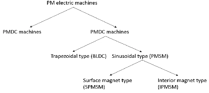
7 The PM machines can be classified as in the diagram in figure 2.1. First, depending on the nature of the stator field excitation, the PM machines can be classified as PM with D.C excitation (PMDC) or PM with A.C excitation (PMAC). The PMDC motor has the same configuration as the conventional DC machine, having a stator winding with brushes and comutator, except for the rotor, where the rotor (field) winding was replace with permanent magnets. The PMAC machine is a synchronous machine, with no brushes or comutator.
Figure 2.1: Permanent magnet machines classification.
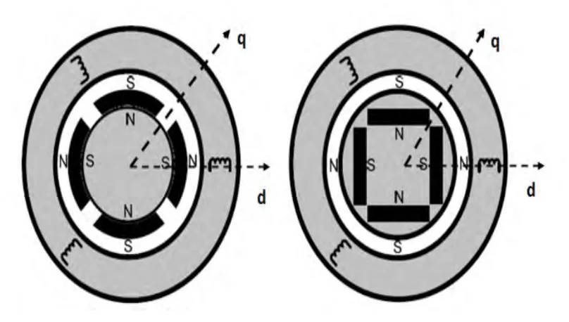
8 The PMSM can be classified into two types, depending on the positioning of the magnets in the rotor of the machine. These are the surface mounted PM machine (SMPMSM) and interior mounted PM machine (IPMSM), like presented in Figure 2.2.
Figure 2.2: Cross section showing the difference between the SMPMSM and IPMSM.
9
𝜉 =𝐿𝑞
𝐿𝑑
2.2. Mathematical Equation of IPMSM
This subchapter present the development of mathematical model for torque control equation by using d-q axis model of the IPMSM, current vector control with Maximum Torque per Ampere (MTPA) and vector control. A mathematical model of the IPMSM is used in order to simulate the performance of the machine in Matlab.
2.2.1. Torque Control Equation Te for IPMSM
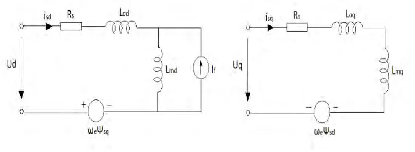
The steady-state analysis of a sinusoidal IPMSM machine with an equivalent circuit and phasor diagram continues the same as a wound field machine apart from that the equivalent field current If should be considered constant, that is
the flux linkage Ψ𝑓 = 𝐿𝑚𝐼𝑓 = 𝑐𝑜𝑛𝑠𝑡𝑎𝑛𝑡. the circuit equations can be written as [3]:
𝑣𝑞𝑠 = 𝑅𝑠𝑖𝑞𝑠+ 𝜔𝑒𝜓́𝑑𝑠 + 𝜔𝑒𝜓̂𝑓+ 𝑑 𝑑𝑡𝜓𝑞𝑠
(1.1)
𝑣𝑑𝑠 = 𝑅𝑠𝑖𝑑𝑠 − 𝜔𝑒𝜓𝑞𝑠+ 𝑑 𝑑𝑡𝜓𝑑𝑠
10 And the torque equation is
𝑇𝑒 =3
2( 𝑃
2) (𝜓𝑑𝑠𝑖𝑞𝑠− 𝜓𝑞𝑠𝑖𝑑𝑠)
(1.3)
The mathematical model of an IPMSM driver can be described by the following equations in a synchronously rotating rotor d-q reference frames as:
𝜓𝑑𝑠 = 𝜓̂𝑓+ 𝐿𝑑𝑠𝑖𝑑𝑠 (1.4)
𝜓𝑞𝑠 = 𝐿𝑞𝑠𝑖𝑞𝑠 (1.5)
𝑇𝑒 =3
2( 𝑃
2) [𝜓̂𝑓𝑖𝑞𝑠+ (𝐿𝑑𝑠− 𝐿𝑞𝑠)𝑖𝑑𝑠𝑖𝑞𝑠] (1.6)
11 Figure 2.3: Equivalent circuit representative of dq voltage equation for IPMSM.
2.2.2. Current Vector Control with Maximum Torque/Ampere
To derive maximum/torque criteria, it is better to normalize the torque expression and express it as function of normalized stator current components. D-axis current id is maintained at zero. Defining the base torque as:
𝑇𝑒 =
3 2(
𝑃 2) 𝜓̂𝑓𝐼𝐵
(1.7)
Where the base current IB is defined as:
𝐼𝐵 =
𝜓̂𝑓
𝐿𝑞𝑠− 𝐿𝑑𝑠 = 𝐼𝑓
𝐿𝑑𝑚 𝐿𝑞𝑠− 𝐿𝑑𝑠