Abstract: In the convolutional operation encodes the transmitted operation encodes the transmitting signal some dispensable information, thus improving the channel data capacity. Viterbi algorithm is commonly used for sensitive models including the decoding the convolutional codes widely used in communication systems such as Satellite communication, Relays and Local wireless channel network. In additional, Viterbi algorithm is used to automatic speech generation and also storage devices as well as application. Cryptography is a scheme used to hide and secure the information without any loss. We have developed a security system of convolutional encoder and Viterbi decoder using DNA cryptography. DNA is used for cryptography due to encryption of convolutional encoder and decryption of Viterbi. Viterbi decoder is one used blocks in data communication systems. Optimizing its word length causes a substantial reduction within the chip space and decryption delay. FPGA synthesis reports the Xilinx tool of using the Viterx-6 family.
Index Terms: Convolution Encoder, Viterbi Decoder, Cryptography, DNA.
I. INTRODUCTION
In the Viterbi algorithm is cost effective. It used in communication systems to decode the convolutional codes. This paper explores that convolutional encoder and Viterbi decoder implementation design [1] using DNA cryptography. This assembled to explain the design of convolutional encoder and decode for constraint length (K) with code rate ½ describes the block diagram for implementing the Viterbi decoder [2], [3]. The importance of Viterbi algorithm’s convolutional codes decoding should not depend on the specific distribution of zeros and ones in the input messages as they are linear. Specific implementation of the Viterbi algorithm [4] during the sub blocks are Branch Metric Unit, Add Compare Select Unit and Survivor Path. However, it was identified to demonstrate the decoding performance that depends on the proportion of elements in the input message bits. In addition, the Viterbi decoder is used in high speed (SERDES) implementations that have critical latency constraints.
Revised Manuscript Received on April 14, 2019.
Fazal Noorbasha, Department of ECE, Koneru Lakshmaiah Education Foundation, Vaddeswaram, Guntur, Andhra Pradesh, India
G.Jhansi, Department of ECE, Koneru Lakshmaiah Education Foundation, Vaddeswaram, Guntur, Andhra Pradesh, India
K.Deepthi, Department of ECE, Koneru Lakshmaiah Education Foundation, Vaddeswaram, Guntur, Andhra Pradesh, India
K Hari Kishore, Department of ECE, Koneru Lakshmaiah Education Foundation, Vaddeswaram, Guntur, Andhra Pradesh, India
Convolutional codes are mainly defined using two constants: code rate and constraint length. The code rate(r) as k / n is a count of bits in the convolution encoder (k) to the no of symbols generate by channel of the convolutional encoder (n) in the encoding cycle. The parameter of constraint k denotes length of the convolutional encoder and indicates that many k bits stage are available to give the combination logic producing the o/p symbols [5]. There are three major components of Viterbi decoders: branch metric unit (BMU), Add-compare-select (ACS) unit and survivor path (SMU) unit. In the Viterbi decoding memory path changes degrade the range of encoding codes. When the relevant state of BMU is the received and expected state of information to the add compare select is the forward logic, when the loop convert the smallest path to find and path arrival at ACS unit. In survivor path to make decision at the Viterbi decoder.
II. RELEVANT IMPLEMENTATION DETAILS OF CONVOLUTIONAL AND VITERBI ALGORITHM
In the encode data of convolutional encoder into code rate of value by using the shifting data at the register to register and output data encryption. Here shift register used to modulo-2 adder encrypt data. Viterbi algorithm architecture is commonly used in the decoding of convolution codes. In the presence of very large-scale integration (VLSI) defects, erroneous outputs may occur which degrade the decoding convolutional codes [9]. Each path connecting the output to a convolutional encoder's input is characterized in terms of its impulse response. It is the response of that path to a symbol applied to its input, with each flip flop in the encoder initially set to zero [10]. Where the selection DNA module encode code of convolutional encoder and sequence of message bits and the decrypted the data to same plaint text into cipher text format of Viterbi decoder modules. The information is changing the by using DNA cryptography. Each path is then characterized in terms of a generator polynomial which is the unit delay transform of the impulse response[11]. The state diagram for the (2, 1, 3) code where 2 represents the encoder's output bit, 1 represents the encoder's input bit, and 3 represents the constraint length in the presentation of the Viterbi algorithm. This is the results of the simulation and implementation of FPGA / ASIC [12]. Figure 1 is showing the Encryption and Decryption Flow Chart.
ASIC Implementation of Convolution Encoder
and Viterbi Decoder Based Cryptography System
Fig. 1 Encryption and Decryption Flow Chart
In the Design flow encryption data input size is 8 bit by using convolutional encoder convert into 16 bit, where this 16- bit gives the DNA by using ASCI converter. In decryption 16-bit data convert into 8-bit by using Viterbi decoder. Figure 1 represents the architecture of the block diagram.
A. Convolutional Encoder
When the data is developed, to reproduce the sequence bits to form Viterbi decoder were the contribution of convolutional encoder [10]. The convolutional algorithm shown in below steps.
Step 1:- Initially, to choose the message bit in the input side at current state and previous state bits to save the number. Step 2:- By shifting the bits, current state during register to register level and calculation of g1 and g2 using XOR operation this is obtain[7] until the new currently save the message bits. Repeat the process up to the change the message bits.
[image:2.595.106.234.51.268.2]Step 3:- In the convolutional encoder most likely encoded by the message bit to change from every predecessor state of the Input bits.
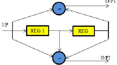
Fig. 2 Block Diagram for Convolutional Encoder
The output sequence obtained using the lower modulo-2 adder O/P2 is (00100110).The combined output sequences
of the two modulo-2 adders are given by
{00001110000100}.For a sample input sequence: 00101101 and the encoder output sequence is obtained as: 00 00 11 10 00 10 10 00. Figure 2 represents the block diagram for convolutional encoder. In the comprehension of its task
[image:2.595.384.469.145.289.2]represented in three diverse graphical ways of the convolutional encoder are state diagram, Trellis diagram and Tree diagram. The state diagram for the code is given in where [9] represents the output bit of the encoder, represents the input bit to the encoder and represents the constraint length. The Convolutional Algorithm Steps shown in figure 3.
Fig. 3 Convolutional Encoder Design Flow
There are four possible states s0, s1and s3. They are represented by the circle. Each state represents the position of the encoder. Where there is a change in the input bit one or zero, transition of present state to the next state is given by the arrowed lines. The encoder outputs are given by the sequence (00 00 11 10 00 01 01 00), which are fed as input to the decoder with code rate ½, whereas k=3. At each instant 2bit per process is considered as the code rate ½. The final decoded output is the 8 bit message 00 10 11 01 sequences, which is originally given as an input for the encoder. When the output message bit of the encoder is given to the Viterbi decoder as input bit.
B. Viterbi Decoder
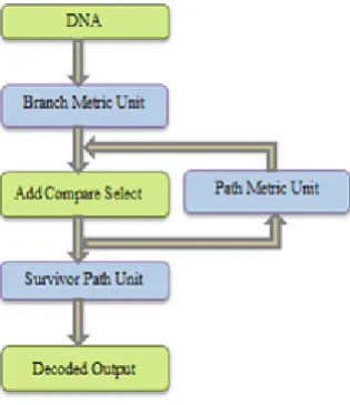
In the Viterbi decoder, where every pair of bit is given to the decoder at the sequence of convolutional encoder. Figure 4 shows the block diagram of the Viterbi decoder. When the Viterbi decoder block diagram briefly explain that branch metric unit connected to the Add compare select unit and again connected to the path metric unit here, the loop structure represented and form the ACS unit[4] . In the received ACS unit to form the Survivor path during that the method to produce the decoded output of the Viterbi algorithm.
[image:2.595.72.265.569.677.2]When the shortest path to form the timing analysis and delay of the path to decoded information. In the Viterbi decoder blocks to explain in detail that BM at time t =1 due to add compare select to form the path metric at smallest count of the trellis to find the survivor path at the decision level of the information . In these Major Blocks are used in the Viterbi algorithm are Branch Metric Unit (BMU, Add Compare Select Unit (ACSU), and Survivor Path Unit (SPU).
a. Branch metric
The principal unit of Hamming distance due to the normal unit and original unit of the message bits of the branch metric unit. Their separation technique of the branch metric unit as certain utilized the hamming distance. In the BM shows the time at t=1. Here hamming distance calculation to branch metric unit .The branch metric unit number of bits shown in above figure 4.The principal unit of the received information to the transmitter from determined contrasted yields.
b. Add Compare Select Unit
In the add compare select to process the sub modules on the path metric unit to generate the trellis of the decision. When the stages of the path has two stages that measurements going to the current state. In path metric to choose the transmitted data to the add compare select and loop operation on the stage. In the adding themselves to characterized the particular path. When the code trellis of shortest path number at the coding bits. In the components are ACS and PMU on the ACSU.
c.Survivor path
[image:3.595.318.532.358.498.2]In the survivor path the decoded data stored to add compare select unit. When the decision making to current data flow into the register level path of the ACS unit. In the next level of the survivor unit to produce the input to ACS output. When the significantly use the data to exchange method. More time taken to convert the register level exchange.
Fig. 5 Viterbi Decoder Design Flow
When the Viterbi decoder design flow described due to the Viterbi decoder outline for signature bits. In the Following steps Viterbi algorithm are shown below.
Step 1:- In the initial stage received and expected message
bits are given to the branch metric unit by using the Hamming distance of the 16 bits double rate to input bit. Set the branch metric and calculate the every current state of paths.
Step 2:- When the ACS unit of bits connected at the trellis of the transmitting data and to choose the each path to form the code number. The path Metric smallest path to form and repeat the steps until the minimum shortest path occur. Step 3:- At the stage of the survivor path connected to decode the data into the ACS unit and path to survivor unit the decoded output.
C. DNA Cryptography
[image:3.595.92.250.530.713.2]When the DNA con store the utilized data in the form of ASCII codes and transmit the information in the pairs of three cipher text of DNA. Where the data of RNA and DNA are in same base sequence like A-0, C-1, G-2, T-3. In the code values of the DNA represents the 00,01,10,11 sequence of bits. Here the A, G, C, T denoted as Adenine, Thymine, Cytosine, Guanine. DNA has double-helix structure [15]. When the Plain text of information is converted into the cipher text to produce output it acts as cryptography, where cryptography used to secure the data without any loss of information at the plain text of the data to modified the original data at the ASCII codes of message bits.
Fig. 6 DNA Cryptography encoding process
In this DNA used to convert the message bits of convolutional encoder of the encoded data. In this paper represented the secure data to encryption and decryption information providing the message bit by using the cryptography. In the cryptography Alice the data plain text by using ASCII code into the cipher text, here key generation to secure information at the possible calculations to developing figure of DNA. When the symbols represented in the data, once the information conveying the results easily to secure. Cryptography to recreate information is privacy and Viterbi decoder to form the decoded output.
III. FPGA SYNTHESIS REPORT AND RESULT ANALYSIS
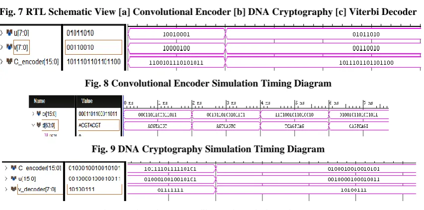
design Here used in Xilinx Vivado. We developed total hardware using in Verilog HDL. Figure 7[a],[b],[c] are shows the RTL (FPGA) schematic view of convolutional encoder, DNA Cryptography and Viterbi decoder modules. In the Figure 8, Figure 9, Figure10 are the simulation results of convolutional encoder, DNA Cryptography and Viterbi
[image:4.595.111.492.132.324.2]decoder modules. The encryption and decryption FPGA device utilization is used as LUT are 8 and I/O are 32 used in Convolutional Encoder, LUT are 23 and I/O are 80 used in DNA Cryptography, LUT are 23 and I/O are 40used in Viterbi decoder.
[image:4.595.91.509.150.505.2]Fig. 7 RTL Schematic View [a] Convolutional Encoder [b] DNA Cryptography [c] Viterbi Decoder
Fig. 8 Convolutional Encoder Simulation Timing Diagram
[image:4.595.88.515.328.539.2]Fig. 9 DNA Cryptography Simulation Timing Diagram
Fig. 10 Viterbi Decoder Simulation Timing Diagram
IV. CONCLUSION
In this paper we have developed a DNA based cryptography using convolutional Encoder and Viterbi Decoder, that increase complexity in each round thus it can increase the security. Time taken for encryption and decryption of data procedure is efficient on the grounds of basic strategies are utilized. So that it increases the efficiency and gives high accuracy. By using same security algorithm, we are optimizing the resource utilization. To implement this designed we have used Verilog HDL. The total process is tested on FPGA Viterx-6 Kit. The total power consumed by encryption module is 3.86 W. The total power consumed by decryption module is 2.11W. The total delay in convolutional encoder is 0.837ns and total delay in Viterbi decoder is 0.345ns. For medical images data analysis this algorithm secures the data. New methodologies can help this algorithm in future to diminish the activity while keeping up the adequate level of security.
REFERENCES
1. N. Prasad , Indrajit Chakrabarti and Santanu Chattopadhyay,”An
Energy-Efficient Network-on-Chip-Based Reconfigurable Viterbi Decoder Architecture”, IEEE Transactions On Circuits And Systems, March 30 2018, pp. 1-12.
2. Parthiban Annamalai, Jyotsna Bapat and Debabrata Das, “Coverage
Enhancement for MTC Devices Using Reduced Search Viterbi Decoder Across RATs”,IEEE Communications Letters, Volume: 20, Issue: 9, Sept. 2016, pp. 1892-1895.
3. Nimisha K T, Prakash Biswagar, “Viterbi Algorithm Based Bluetooth
Low Energy Receiver for IoT”, 2nd IEEE International Conference in Electronics Information & Communication Technology (RTEICT), May 2017, pp. 19-20.
4. Upputuri Neelima, Fazal Noorbasha, “Data Encryption and Decryption
5. Fazal Noorbasha, M. Manasa, R. Tulasi Gouthami, S. Sruthi, D. Hari Priya, N. Prashanth, And Md. Zia Ur Rahman, “FPGA Implementation Of Cryptographic Systems For Symmetric Encryption”, Journal of
Theoretical and Applied Information Technology, 15th May 2017.
Vol.95. No 9, PP. 2038-2045
6. Fazal Noorbasha, C.H. Vainatheyi, R. Goutham, P. Raviteja, B.
Karthik, “Implementation of Image Secured Hybrid AES - DNA Algorithm Using Verilog HDL”, Jour of Adv Research in Dynamical & Control Systems, Vol. 10, 02-Special Issue, 2018, PP. 452-458.
7. G Divya, Fazal Noorbasha, “Implementation of DNA Based
Cryptography Using OTP Random Key Generation Process”, Jour of Adv Research in Dynamical & Control Systems, Vol. 10, 02-Special Issue, 2018, PP. 481-490.
8. Jung Uk Kim ; Hak Gu Kim ; Yong Man Ro,” Iterative deep
convolutional encoder-decoder network for medical image
segmentation”, 39th Annual International Conference of the IEEE Engineering , Nov 2017, pp . 685 – 688.
9. Vijay Badrinarayanan; Alex Kendall; Roberto Cipolla,” SegNet: A
Deep Convolutional Encoder-Decoder Architecture for Image Segmentation” ,IEEE Transactions on Pattern Analysis and Machine Intelligence,Vol39, Issue: 12, Dec. 1 2017, pp. 2481 – 2495.
10. G. Purohit, Member, K. S. Raju, V. K. Chaubey, “A New XOR-Free
Approach for Implementation of Convolutional Encoder”,IEEE Embedded Systems Letters, Vol 8, Issue: 1, March 2016, pp.22 – 25.
11. Xuncai Zhang, Zheng Zhou, Ying Niu ,“An Image Encryption Method
Based on the Feistel Network and Dynamic DNA Encoding” IEEE Photonics Journal, vol 10, Dec 2018, pp.1-14.
12. Wei Feng, Yi-Gang He,“Cryptanalysis and Improvement of the
Hyper-Chaotic Image Encryption Scheme Based on DNA Encoding and Scrambling”, IEEE Photonics Journal Cryptanalysis and Improvement of the HIES,Vol 10,December 2018, pp.1-15.
13. Xing-Quan Fu, Bo-Cheng Liu, Yi-Yuan Xie ,Wei Li and Yong Liu3,”
Image Encryption-Then-Transmission Using DNA Encryption
Algorithm and The Double Chaos”, IEEE Photonics Journal Image Encryption-Then-Transmission,Vol. 10, Issue: 3 , June 2018 , pp.1-15.
14. Chongfu Zhang ; Wei Zhang ; Chen Chen ; Xiujun He ; Kun Qiu,”
Physical-Enhanced Secure Strategy for OFDMA-PON Using Chaos and Deoxyribonucleic Acid Encoding”, Journal of Lightwave Technology, Volume: 36 , Issue: 9,May 1,2018, pp. 1706 – 1712
15. Shuliang Sun,“A Novel Hyperchaotic Image Encryption Scheme Based
on DNA Encoding, Pixel-Level Scrambling andBit-Level Scrambling”, IEEE Photonics Journal Novel Hyperchaotic Image Encryption Scheme,Vol. 10, April 2018, pp.1-14.
16. Yadlapati, A., Kakarla, H.K. An Advanced AXI Protocol Verification
using Verilog HDL (2015) Wulfenia, 22 (4), pp. 307-314.
17. Bindu Bhargavi, K., Hari Kishore, K. Low Power Bist on Memory
Interface Logic (2015) International Journal of Applied Engineering Research, 10 (8), pp. 21079-21090.
18. [18] Charan, N.S., Kishore, K.H. Recognization of delay faults in
cluster based FPGA using BIST (2016) Indian Journal of Science and Technology, 9 (28).
19. Hari Kishore, K., Aswin Kumar, C.V.R.N., Vijay Srinivas, T.,
Govardhan, G.V., Pavan Kumar, C.N., Venkatesh, R.V. Design and analysis of high efficient UART on spartan-6 and virtex-7 devices (2015) International Journal of Applied Engineering Research, 10 (9), pp. 23043-23052.
20. Kante, S., Kakarla, H.K., Yadlapati, A. Design and verification of AMBA AHB-lite protocol using Verilog HDL (2016) International Journal of Engineering and Technology, 8 (2), pp. 734-741.
21. Bandlamoodi, S., Hari Kishore, K. An FPGA implementation of
phase-locked loop (PLL) with self-healing VCO (2015) International Journal of Applied Engineering Research, 10 (14), pp. 34137-34139.
22. Murali, A., Hari Kishore, K., Rama Krishna, C.P., Kumar, S., Trinadha
Rao, A. Integrating the reconfigurable devices using slow-changing key technique to achieve high performance (2017) Proceedings - 7th IEEE International Advanced Computing Conference, IACC 2017, art. no. 7976849, pp. 530-534.
23. A. Surendar, K. H. Kishore, M. Kavitha, A. Z. Ibatova, V. Samavatian
“Effects of Thermo-Mechanical Fatigue and Low Cycle Fatigue Interaction on Performance of Solder Joints” IEEE Transactions on Device and Materials Reliability, P-ISSN: 1530-4388, E-ISSN: 1558-2574, Vol No: 18, Issue No: 4, Page No: 606-612, December-2018.
24. N Bala Dastagiri K Hari Kishore “A 14-bit 10kS/s Power Efficient
65nm SAR ADC for Cardiac Implantable Medical Devices” International Journal of Engineering and Technology (UAE), ISSN No: 2227-524X, Vol No: 7, Issue No: 2.8, Page No: 34-39, March 2018.
25. N Bala Dastagiri, Kakarla Hari Kishore "Reduction of Kickback Noise
in Latched Comparators for Cardiac IMDs” Indian Journal of Science and Technology, ISSN No: 0974-6846, Vol No.9, Issue No.43, Page: 1-6, November 2016.
26. N Bala Dastagiri, K Hari Kishore "Analysis of Low Power Low
Kickback Noise in Dynamic Comparators in Pacemakers” Indian Journal of Science and Technology, ISSN No: 0974-6846, Vol No.9, Issue No.44, page: 1-4, November 2016.
27. Meka Bharadwaj, Hari Kishore "Enhanced Launch-Off-Capture
Testing Using BIST Designs” Journal of Engineering and Applied Sciences, ISSN No: 1816-949X, Vol No.12, Issue No.3, page: 636-643, April 2017.
28. Dr. Seetaiah Kilaru, Hari Kishore K, Sravani T, Anvesh Chowdary L, Balaji T “Review and Analysis of Promising Technologies with Respect to fifth Generation Networks”, 2014 First International Conference on Networks and Soft Computing,ISSN:978-1-4799-3486-7/14,pp.248-251,August 2014.
29. P Bala Gopal, K Hari Kishore, R.R Kalyan Venkatesh, P Harinath
Mandalapu “An FPGA Implementation of On Chip UART Testing with BIST Techniques”, International Journal of Applied Engineering Research, ISSN 0973-4562, Volume 10, Number 14 , pp. 34047-34051, August 2015.