Abstract: Unchecked vibrations can generate noise, accelerate rates of wear, cause safety glitches, resulting in low efficiency and at times a costly failure in mechanical components. Just like gear and shafts, the gearbox casing is a vital transmission component. So, while designing, the gearbox casing strength is a significant parameter to consider. The reasons for vibrations are external disturbances, load fluctuations, transmission faults, gear mesh stiffness and many other reasons. Therefore, it is vital to estimate and settle the limits of vibrations and noise in designing stage using Finite Element Analysis (FEA). This paper comprises dynamic analysis and Structural born noise calculation for a single stage helical gearbox casing by employing Finite Element Analysis. Using SOLIDWORKS the 3D model of gearbox was prepared and using ANSYS 18.1 software finite element simulation was done. To forecast the natural frequencies and dynamic responses of the system for the excitation frequencies and its harmonics, Modal and Harmonic analysis was carried out. The estimation of natural frequencies of the gearbox casing in Modal analysis aids in keeping the natural frequency away from resonance frequencies. The magnitude of the natural frequencies of the gearbox is estimated using Harmonic analysis. The results of harmonic analysis were used as input for acoustic study and the Structural Born Noise (SBN)was measured. Obtained noise values are well within the limits and the design was verified.
I. INTRODUCTION
Casing is a portion of gear which supports the shaft, bearing and the gear loading. The power transmission processes aren’t as simple as it seems. The constituents or portions of the transmission are exposed to changing loading environments. Noise and vibration are created by these fluctuating loading and boundary conditions [1]. Cast iron is employed as damping to remove and withstand the vibration waves. Vibration is the chosen study parameter because the two vital parameters for the transmission let down are noise and vibration. [2]. Under excitation condition helical gearboxes are exposed to noise and vibration. The major sources of excitation are internal excitation forces, mesh stiffness forces,
Revised Manuscript Received on May 10 ,2019
M.Akilesh, UG Student, Department of Mechanical Engg, Sri Krishna
College of Engineering and Technology, Coimbatore, TN, India.
G. Kathiresan, Head in Engineering and R&D, Shanthi Gears Limited,
Coimbatore, TN, India.
R.Soundararajan*, Associate Professor, Department of Mechanical
Engg, Sri Krishna College of Engineering and Technology, Coimbatore, TN, India.
G.Dinesh, UG Student, Department of Mechanical Engg, Sri Krishna
College of Engineering and Technology, Coimbatore, TN, India.
V. Abhay Charan, UG Student, Department of Mechanical Engg, Sri
Krishna College of Engineering and Technology, Coimbatore, TN, India.
load, speed variation and gear defects. The single stage helical gearbox casing encloses helical gears and bearings for power transmission. This Gearbox serves to decrease speed and upsurge torque [3]. Vibration to the gearbox casing will be produced from the motion of the gear. In the design of several constructions, the modal analysis is avital element principally in the initial expansion stages. Input speed and output speed of the shaft, gear mesh frequencies, bearing frequencies are several excitation frequencies in gearboxes. Gearbox can be affected if excitation frequencies and natural frequencies are similar. Thus, its vivacious to carry out a dynamic charm analysis on the gearbox [4]. More practical recommendations of a gearbox casing structure design are established with FEM analysis on the gearbox casing and complete consideration on structural parameters agreeing to the dynamic load of gear meshing and harmonic exciting load. Researchers achieved numerous studies on dynamic response of power transmission system for the previous three decades, but it is an intricate procedure in terms of design, manufacturing, or mathematical modelling [5].
Ashwani Kumar et al., passed out dynamic analysis of transmission casing by finite element simulation employing ANSYS 14.5 software and considered the vibration patterns for material like cast iron, alloys of Al, Mg, stainless steel, and composites. From simulation outcomes, first twenty natural frequencies of the gearbox using cast iron, alloys of Al, Mg, stainless steel, and composites of the casing were obtained [6].
R. V. Nigadeet al., lectures FE analysis and vibration testing of gearbox top cover of an integrally geared centrifugal compressor. By both analytical and experimental techniques, he confirmed and validated the vibration characteristics of the gearbox top cover. The outcomes demonstrate that the natural frequencies of the gearbox top cover projected by FEA are inside 8 percent of the restrained natural frequencies of the modal test data, thus settling the close agreement between FEA and experimental data. To study the effect of wall and rib thickness of the gearbox top cover on its natural frequencies and accompanying mode shapes, a parametric study was conducted using FEA. The noise calculation was not calculated in the literature [7]. Guangyao Zhao et al., prepared three-dimensional solid modeling of the automobile gearbox, FE analysis models of static, harmonic and transient response load are established with help of correlation theory. Transient load of the gearbox casing at
various working gears is premeditated on the basis of ADAMS dynamic response
Numerical Simulation of Vibration and
Structural Born Noise Analysis of Industrial
Gearbox
simulation of diverse gears. Improvements regarding transmission working restrictions matching and the gearbox structural design are suggested [8].
BalasahebSahebraoVikhe deliberate the design analysis of a three stage Industrial Helical gearbox casing employing Finite Element Analysis (FEA) Method. The enhanced design for the gearbox casing has the supreme performance sansany defects and with minimum loads on the casing originates with the assistance of this process. To verify if the design is safe or not, FEA also be performed on design of the gearbox housing [9].
M. Sofian et al., premeditated about dynamic analysis of the gearbox casing using FE Analysis to estimate the natural frequency and harmonic frequency response of gearbox casing to evade resonance for the gearbox casing. The results exhibited the array of the frequency that is appropriate for gearbox casing which can circumvent extreme amplitude [10].
To prevent the failure of gearbox it is very important and indispensable to analyse the gearbox casing before implementing it in a real time working environment. So, many researchers are focusing on the vibration and noise analysis of the gearboxes. A unique single stage helical gearbox casing was designed in this work and checked for vibration and SBN analysis. To avoid failure and estimate the structural strength of the casing in a real working environment, an attempt was made to perform a structural, dynamic and SBN analysis on the gearbox casing.
II. Three-Dimensional Model of Gearbox Casing The three-Dimensional solid CAD model of the gearbox casing modelled by means of SOLIDWORKS is shown in Figure 1. ANSYS workbench 18.1 was used for pre-processing, solving and post processing. To ensure more precise results, mesh convergence was carried out and appropriate mesh properties were used for analysis. Employing Solid 187 element (3-Dimensional 10-Node Tetrahedral solid element) the fine meshing is done on the gearbox casing and shown in Figure 2. The FE model entails78,749 elements and 153354 nodes.
[image:2.595.342.530.80.293.2]Fig 1. Single stage Helical Gearbox casing
[image:2.595.93.262.568.749.2]Fig 2. FE model of Helical Gearbox casing III. Material Properties and Boundary conditions Table 1displays the material properties of the Gearbox casing. Gearbox casing is manufactured by several process based on the application of the gearbox. Cast iron is used for the Gearbox casing due to its damping properties since many years. Using connecting bolts and the base, gearbox casing is strongly mounted. In vibration analysis, boundary conditions have noteworthy role. For modal analysis, there are two boundary conditions in ANSYS. These are free and fixed boundary conditions. Figure 3 shows the fixed boundary condition and displayed in dark blue colour in the figure. In this analysis, bearing forces was given normally to bearing surfaces and the outcomes are noted down. Applied loading conditions are shown in Figure 4. The red colour in the figure displays the constraint condition.
Table 1 Material properties of Gearbox casing S. No Properties Description 1 Material with grade Gray cast iron grade FG260
2 Elastic modulus
(MPa)
1.28e05
3 Poisson ratio 0.26
4 Density of material (Kg/m3)
7200
5 Ultimate tensile
strength (MPa)
Fig 3. Fixed constraint boundary condition
Fig 4. Loading conditions in gearbox casing. IV. Methodology
Above-mentioned material properties, boundary conditions and applied load conditions are used to carry out the static and dynamic analysis of the Gearbox casing. To treasure the complete quantity of stresses and displacement in the gearbox, static analysis of the gearbox casing was carried out. Dynamic analysis was carried out in order to find out the excitation and maximum response frequencies of the gearbox casing to avoid resonance. The analysis results show the natural frequencies, mode shapes, magnitude at the excitation frequencies and the structural born noise analysis of the gearbox.
Gear mesh frequency=k *(N/60)Hz, where k= number of teeth on the gear
N = speed of the shaft
V. Results and Discussion A. Results of Static Analysis of Gearbox
Static structural analysis is carried out in order to find out the stress, strain and the displacement along the three axes of the gearbox casing. The meshing, boundary conditions and applied load conditions on the gearbox for the static analysis are shown in Figures 2, 3 and 4 respectively. In Table 2,
[image:3.595.313.538.136.356.2]maximum stress and the total deformation of the single stage helical gearbox for the given boundary conditions and applied loading condition are shown. The maximum stress plot and the total deformation of the gearbox casing are shown in Figure 5 and 6 respectively.
Table 2 Results of Static analysis of Gearbox
S.No Description Results
1 Equivalent von-Mises
stress (MPa)
36.72
2 Total deformation (mm) 0.184
Fig 5. von-Mises stress of gearbox casing
Fig 6. Total Deformation contour of gearbox casing B. Modal Analysis results of Gearbox
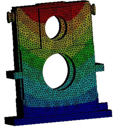
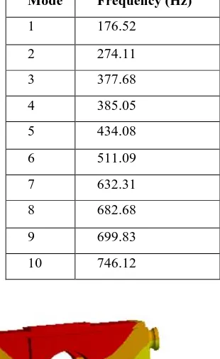
The natural frequencies of the gearbox are calculated for the boundary conditions as shown in the figure 3 in Modal Analysis. Using ANSYS, the natural frequencies and the mode shapes of the single stage helical gearbox are estimated. The mode shapes such as bending, torsional, axial bending vibration, combination of two vibrations were obtained from the analysis. For natural frequency calculation, damping is ignored. In Table 3, the natural frequencies of the single stage helical gearbox were tabulated. The mode shapes of the frequencies 176.52, 385.05, 632.31 and 746.12 Hz are deformation along X-axis, deformation along Y-axis, bending and twisting respectively as shown in Figure 7 (a, b, c and d) respectively.
[image:3.595.66.215.248.449.2]Mode Frequency (Hz)
1 176.52
2 274.11
3 377.68
4 385.05
5 434.08
6 511.09
7 632.31
8 682.68
9 699.83
10 746.12
(a) Mode 1: 176.52 Hz
(b) Mode 4: 385.05 Hz
(c) Mode 7: 632.31 Hz
[image:4.595.55.525.56.638.2](d) Mode 10: 746.12 Hz
Fig 7. Mode shapes of Natural frequencies
C. Harmonic analysis results
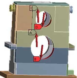
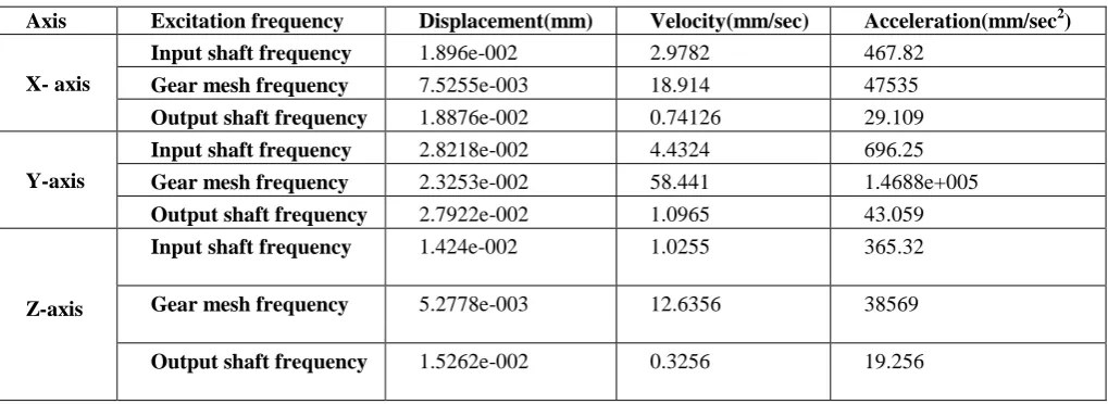
The first ten natural frequencies of the gearbox were calculated from the modal analysis. The excitation frequencies like input shaft frequency, output shaft frequency and the gear mesh frequencies were calculated and it was concluded that the natural frequencies were well away from the resonance condition. The harmonic analysis is done in order to find out the magnitude of the dynamic response at the excitation frequencies. The results of the harmonic analysis of the gearbox along X-axis and Y-axis for displacement, velocity and acceleration at a particular location as shown in Figure 8 are given below in the table 3.
[image:4.595.89.244.65.318.2]Fig 8. Location for response
Table 4 Magnitude of the frequency at excitation frequencies
Axis Excitation frequency Displacement(mm) Velocity(mm/sec) Acceleration(mm/sec2)
X- axis
Input shaft frequency 1.896e-002 2.9782 467.82
Gear mesh frequency 7.5255e-003 18.914 47535
Output shaft frequency 1.8876e-002 0.74126 29.109
Y-axis
Input shaft frequency 2.8218e-002 4.4324 696.25
Gear mesh frequency 2.3253e-002 58.441 1.4688e+005
Output shaft frequency 2.7922e-002 1.0965 43.059
Z-axis
Input shaft frequency 1.424e-002 1.0255 365.32
Gear mesh frequency 5.2778e-003 12.6356 38569
Output shaft frequency 1.5262e-002 0.3256 19.256
D. Structural born noise results of Gearbox
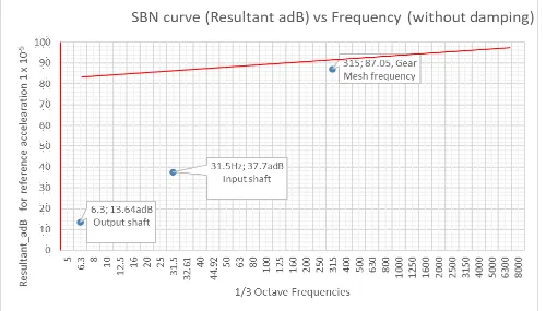
Structural born noise of the gearbox was calculated at the excitation frequencies in order to ensure that the noise from the gearbox are well within the acceptable limits. At each excitation frequencies, the noise was calculated at 10 different locations. The acceleration results were calculated for all the three axes of the gearbox and the obtained acceleration values along Y-axis were used to calculate SBN in decibels. The response was recorded for 1/3 octave frequencies in order to
Fig 9. 1/3 octave frequencies Vs Resultant adB for acceleration VI. CONCLUSION
In this study, the design and analysis of the single stage helical gearbox was done using Finite Element Analysis to guarantee its safe working and smooth running in real time working environment.
It is found that the overall stress and displacement was within the permissible limit for the given load and boundary conditions from the static structural analysis.
In order to know the natural frequencies of the gearbox casing, the modal analysis was performed. The estimated natural frequencies were compared with the excitation frequencies (operating frequency) and verified for resonance. No resonance condition was found.
Calculation was carried out to estimate the structural born noise. It was obtained from the analysis that the results were well within the acceptable limits. From the results, it is confirmed that the noise and the vibration on the gearbox was well within the standard limits and hence it is suggested for real time applications in industries.
REFERENCES
1. Ashwani Kumar, Himanshu Jaiswal, Faraz Ahmad and Pravin P Patil, Dynamic Vibration Characteristics Analysis of Truck Transmission Gearbox Casing with Fixed Constraint of Vehicle Frame Based on FEA, 2014, Procedia Engineering 97, pp 1107 – 1115.
2. Peter Weis, LubosKusera, Peter Pechae and Martin Mocilan, Modal analysis of gearbox housing with applied load, Procedia Engineering,2017, 192, pp 953 – 958.
3. TENG Hongzhi, ZHAO Jianmin, nA Xi sheng, nAYunxian, ZHANG Xinghui and CAlLiying, Experimental Study on Gearbox Prognosis Using Total Life Vibration Analysis, Prognostics & System Health Management Conference, 2011.
4. Shrenik M. Patil and Prof. S. M. Pise, Modal and Stress Analysis of Differential Gearbox Casing with Optimization, Int. Journal of Engineering Research and Application, 2013, Volume 3, Issue 6, pp.188-193.
5. C. Brecher, C. Löpenhaus and M. Schroers, Analysis of dynamic excitation behavior of a two-stage spur gearbox, Procedia CIRP 6, 2017, pp 369 – 374.
6. Ashwani Kumar, Arpit Dwivedi, Himanshu Jaiswal and Pravin P. Patil, Material-Based Vibration Characteristic Analysis of Heavy Vehicle Transmission Gearbox Casing Using Finite Element Analysis, Springer India, 2015.
7. R. V. Nigade, T.A.Jadhav and A.M.Bhide, Vibration Analysis of Gearbox Top Cover, International Journal of Innovations in Engineering and Technology (IJIET), 2012, Volume-1 Issue-4.
8. Guangyao Zhao, Peng Fu, Shuwen Zhou and Shange Tong, Dynamic Mechanical Analysis of Automotive Gearbox Casing, Advanced Materials Research, 2011, Volume- 230-232, pp 539-543.
9. BalasahebSahebraoVikhe, Design Analysis Of Industrial Gear Box Casing, International Research Journal of Engineering and Technology (IRJET), 2016, Volume-03 Issue-11.
10. M. Sofian, D. Hazry, K. Saifullah, M. Tasyrif and K.SallehI.Ishak, A study of Vibration Analysis for Gearbox CasingUsing Finite Element Analysis, Proceedings of International Conference on Applications and Design in Mechanical Engineering (ICADME), 2009.
AUTHORSPROFILE
M. Akilesh has currently completed his under
graduation in Department of Mechanical Engineering. His area of research includes design, analysis, and additive manufacturing methods. To his credit, he has published various research papers in reputed journals.
Mr. G. Kathiresan is currently working as Head in
Engineering and R&D at Shanthi Gears Limited, Coimbatore. His research area includes analysis and optimization of various critical components.
[image:6.595.47.547.60.345.2]Dr. R. Soundararajan is currently working as an Associate Professor in Department of Mechanical Engineering. His area of research includes Design, Manufacturing technology and Optimization. To his credit, he has published various research papers in reputed journals and filed various patent. He is a member in various professional bodies.
G. Dinesh has currently completed his under
graduation in Department of Mechanical Engineering. His research area includes Design and Manufacturing.
V. Abhay Charan has currently completed his