Copyright © and Moral Rights for this thesis are retained by the author and/or other
copyright owners. A copy can be downloaded for personal non-commercial
research or study, without prior permission or charge. This thesis cannot be
reproduced or quoted extensively from without first obtaining permission in writing
from the copyright holder/s. The content must not be changed in any way or sold
commercially in any format or medium without the formal permission of the
copyright holders.
When referring to this work, full bibliographic details including the author, title,
awarding institution and date of the thesis must be given e.g.
AUTHOR (year of submission) "Full thesis title", University of Southampton, name
of the University School or Department, PhD Thesis, pagination
UNIVERSITY OF SOUTHAMPTON
FACULTY OF ENGINEERING, SCIENCE & MATHEMATICS
School of Engineering Sciences
Genetic Algorithm based Optimisation of FRP
Composite Plates in Ship Structures
by
Komsan Maneepan
Thesis for the degree of Doctor of Philosophy
I would like to express my sincere gratitude to Professor Ajit Shenoi, Dr. Han Koo Jeong
and Dr. James Blake for their academic supervision, support and kind encouragement
throughout the work period.
I also express my thanks to Prof. W.G. Price, the head of the School of Engineering
Sciences, Prof. P.A. Wilson and all members of Fluid Interaction Research group for
their kind support. Special thanks to Dr. Ming-Yi Tan for his technical support. I also
would like to thank Dr. A.K. Nayak, Dr. N. Samphathkumar, Dr S.W. Boyd and Dr. K.
Djidjeli for the useful discussions.
I wish to thank my mother, my sisters and my wife for their never ending support in
my life. I also dedicate this work to my father. Finally, thanks to the Royal Thai Navy
for providing me with financial support throughout the research program.
Composite materials (herein means Fibre Reinforced Plastic, FRP) are increasingly used
in the construction of marine vehicles because of their outstanding strength, stiffness and
light weight properties. However, the use of FRP comes with difficulties in the design
process as a result of the large number of design variables involved: composite material
design, topologies and laminate schemes. All variables are related to each other leading to
a high dimensional and flexible design space. It is hard to use traditional design methods
in order to gain solutions for an initial design stage in a short time. Hence, this thesis
deals with the presentation of a structural synthesis (optimisation framework) for plate
components of composite ship structures. The framework broadly consists of an
optimi-sation technique and structural analytical methods.
To make the framework compatible with the nature of composite ship structural
de-sign problems, the Genetic Algorithm (GA) is selected as the optimisation tool because
of its robustness, its ability in dealing with both continuous and discrete variables and its
excellent searching for a global optimum. The typical plate types in a ship structure are
the stiffened and unstiffened plates. For a stiffened plate, the combination of the grillage
analysis of energy method based on Navier solution and an equivalent elastic properties
approach are introduced. Using this, it is possible to produce layer by layer optimisation
results for the base plate, web and crown of the stiffened plate. Unfortunately, solutions of
the adopted grillage analysis do not cover the mechanical behaviour of the plate between
stiffeners so the Higher-Order Shear Deformation Theory (HSDT) must be employed.
promised computational time. Then stiffness, strength and stability can be considered in
the design problem.
In addition, to achieve the program of the structural synthesis, various computational
modules are implemented according to the evaluation of composite micromechanics
prop-erties, maximum stress failure criteria and structural weight function. Then the main
modules are validated with available resources. The usefulness of the program has been
proved by comparing it with the optimal solutions from finite element software. Finally,
many application examples of secondary and tertiary composite ship structures are
pre-sented. The optimal results prove the success of the optimisation framework. This could
List of Publications produced from this thesis
1. Maneepan K., Jeong H.K. and Shenoi R.A. (2005) Optimisation of FRP tophat
stiff-ened single skin and monocoque sandwich plates using genetic algorithm, Proceeding of
15th international offshore and polar engineering conference, June 19-24, Seoul, Korea,
pp. 513-518
2. Maneepan K., Shenoi R.A., Jeong H.K. and Blake J.I.R. (2006) Multi-objective
opti-misation of orthogonally tophat-stiffened composite laminates plates, Proceedings of 25th
international conference on offshore mechanics and arctic engineering, June 4-9, 2006,
Hamburg, Germany, OMAE2006-92442
3. Maneepan K., Shenoi R.A., Blake J.I.R. and Jeong H.K. (2007) Genetic Algorithms
(GAs) based optimisation of FRP composite plated grillages in ship structures,
Acknowledgements i
Abstract ii
List of Figures ix
List of Tables xii
Nomenclature xiv
1 Introduction 1
1.1 General introduction . . . 1
1.2 Motivation and research aim . . . 3
2 Review of optimisation techniques for structural design 4 2.1 Introduction . . . 4
2.2 Background to FRP composites . . . 4
2.3 Marine applications of FRP composites . . . 10
2.4 Design methods . . . 12
2.5 Development of optimisation techniques . . . 16
2.6 Applications of optimisation techniques to composite structures . . . 23
2.7 Summary . . . 27
3 Review of structural solutions for FRP composite plates 29 3.1 Introduction . . . 29
3.2 Background to FRP composite mechanics . . . 29
3.3 Analytical methods for stiffened plates . . . 33
3.3.1 Grillage analysis . . . 33
3.3.2 Orthotropic plate theory methods . . . 36
3.3.3 Folded plate methods . . . 38
3.4 Analytical methods of unstiffened plate . . . 40
3.5 Numerical methods for composite structures . . . 44
3.6 Summary . . . 47
4 Methodology 50 4.1 Introduction . . . 50
4.2 Methodology adopted . . . 50
4.3 Description of the optimisation framework . . . 51
5 Structural analysis and Optimisation procedure 54 5.1 Introduction . . . 54
5.2 Grillage analysis . . . 54
5.3 Higher order shear deformation theory (HSDT) . . . 59
5.4 Genetic Algorithm . . . 64
5.4.1 Introduction . . . 64
5.4.2 Initial population . . . 64
5.4.3 Evaluation . . . 67
5.4.4 Exploiting operator . . . 68
5.4.5 Exploring operators . . . 70
5.5 Design variable representation . . . 72
5.6 Weight function . . . 73
6 Validation and testing 75 6.1 Introduction . . . 75
6.2 Grillage analysis . . . 75
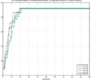
6.4.1 Varying GA operators . . . 83
6.4.2 Varying starting points . . . 84
6.5 Comparison with ANSYS optimisation . . . 86
7 Applications to stiffened plates 91 7.1 Introduction . . . 91
7.2 Parametric study of grillage structures . . . 94
7.3 Unidirectional stiffened plate . . . 98
7.3.1 Maximise stiffness . . . 98
7.3.2 Maximise strength . . . 99
7.3.3 Weight minimisation . . . 101
7.4 Tophat cross stiffened plate . . . 103
7.4.1 Maximise stiffness . . . 103
7.4.2 Maximise strength . . . 105
7.4.3 Weight minimisation . . . 106
8 Applications to unstiffened plates 110 8.1 Introduction . . . 110
8.2 Parametric study . . . 110
8.3 Laminated plate . . . 112
8.3.1 Maximise stiffness . . . 112
8.3.2 Maximise strength . . . 114
8.3.3 Maximisation of critical buckling load . . . 116
9 Conclusion and further work 119 9.1 Conclusion . . . 119
9.2 Further work . . . 121
A Composite properties 123
1.1 Stiffened single skin structure . . . 2
2.1 The comparative fibre cost . . . 6
2.2 HMS Sandown . . . 11
2.3 Design decision process . . . 17
2.4 Classification of optimisation techniques . . . 18
2.5 Global and local minimum of the multiple-peak function . . . 22
3.1 Stress components . . . 30
3.2 An orthotropic lamina with its principal material axes arbitrary orientated with respect to reference co-ordinate axes . . . 32
3.3 General derivation procedures of equivalent single layer theories . . . 41
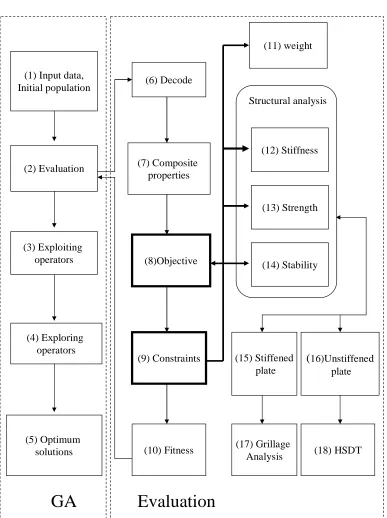
4.1 Optimisation framework . . . 53
5.1 (a) Tophat cross stiffened plate and (b) Grillage representation for the stiffened plate . . . 55
5.2 (a) Tophat cross section of girders and beams with the local coordinate for fibre layup (b) Geometric parameters of girders and (c) Geometric param-eters of beams . . . 56
5.3 The co-ordinate system of a rectangular laminated plate of thickness (t) subjected to in-plane compressive edge forces ( ˆNxx =−Nxx0 ,Nˆyy =−Nyy0 ) 60 5.4 The diagram of Genetic Algorithms . . . 65
5.5 Binary representation of a laminate element . . . 72
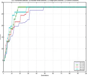
6.1 GA run by varying a couple of operators with GA parameters set-1 . . . . 83
6.2 GA run by varying a couple of operators with GA parameters set-2 . . . . 84
6.3 GA run for different starting point . . . 85
6.4 Convergence time of each starting point . . . 86
6.5 The 1×1 blade stiffened plate with its dimensions . . . 87
6.6 The convergence of GA run for 1×1 grillage . . . 88
6.7 The iteration history of ANSYS optimisation . . . 90
7.1 Positions at which failure index is considered for unidirectional stiffened plate . . . 93
7.2 Positions at which failure index is considered for cross stiffened plate . . . 94
7.3 Normalised maximum deflection vs. number of girders by fixing number of beams at five for three length-to-width ratio cases . . . 95
7.4 Normalised values of direct- and shear- stresses on the crown element of the middle girder and the middle beam vs. number of girders by fixed number of beams at five . . . 96
7.5 The influence of fibre angle on Failure Index (FI) from maximum stress criterion . . . 97
7.6 Convergence of GA run for maximisation of strength: unidirectional stiff-ened plates . . . 100
7.7 Convergence of GA run for weight minimisation: unidirectional stiffened plates . . . 101
7.8 Convergence of GA run for maximisation of stiffness: cross stiffened plates 103 7.9 Convergence of GA run for maximisation of strength: cross stiffened plates 105 7.10 Convergence of GA run for weight minimisation: cross stiffened plates . . . 107
8.1 The effect of Young’s modulus of fibre and layer thickness on central de-flection . . . 111
8.4 Convergence of GA run for maximisation of strength: laminated plate . . . 115
8.5 Convergence of GA run for maximisation of critical buckling load for
uni-axial compression: laminated plate . . . 117
8.6 Convergence of GA run for maximisation of critical buckling load for biaxial
2.1 Marine composite construction productivity rates from Eric Greene
Asso-ciates Inc. (2001) . . . 9
2.2 Characteristics of optimisation techniques . . . 28
3.1 The contracted notation . . . 31
6.1 Comparison between the results of the developed programs from energy
method based Navier solution (EM), Orthrotropic Plate Method (OPM),
Force Method (FM) and the results of Clarkson (1965) for the maximum
deflectionδmax(mm) and maximum stress of girderσmaxg (MP a) and beam
σb
max (MP a). . . 77
6.2 Comparison between the results of the developed program of equivalent
elastic properties and those of Datoo (1991) . . . 78
6.3 Comparison of the developed program shear stress calculation with Datoo
(1991) . . . 79
6.4 Comparison between nondimensionalised maximum deflections ( ¯w) of the
developed TSDT program and those of TSDT,FSDT,CLPT and 3-D
elas-ticity solution (3-D) from Reddy (1997) . . . 80
6.5 Nondimensionalised stresses in a three layer [0/90/0] simply supported
square laminate under sinusoidal transverse load . . . 81
6.6 Comparison of nondimensionalised uniaxial buckling loads (N) of the
de-veloped TSDT program with those of TSDT, FSDT and CLPT of Reddy
(1997) . . . 82
developed TSDT program and those of FSDT with shear correction factor
(K) = 5/6 of Reddy (1997) . . . 82
6.8 The optimal results of 1×1 blade stiffened plate . . . 89
7.1 Material properties of a resin and fibres from Smith [105] . . . 92
7.2 Minimisation of the central deflection for the unidirectional stiffened
lami-nated plate . . . 99
7.3 Minimisation of Failure Index (FI) at three positions on the unidirectional
stiffened laminated plate . . . 99
7.4 Weight minimisation of unidirectional stiffened laminated plate subjected
to stiffness and strength constraints . . . 102
7.5 Minimisation of central deflection of cross stiffened laminated plate . . . . 104
7.6 Minimisation of Failure Index (FI) at five positions on the cross stiffened
laminated plate . . . 106
7.7 Weight minimisation of cross stiffened laminated plate under stiffness and
strength constraints . . . 109
8.1 Minimisation of central deflection for the unstiffened laminated plate . . . 114
8.2 Maximise strength of the unstiffened laminated plate . . . 114
Aw Areal weight
a Area of ith element
ab, ag Crown width of beams and girders
b, g Number of beams and girders
B, L Width and length of a plate
Db, Dg Flexural rigidity of beam and girder
dna(i) Vertical distance from neutral axis of
the girder or beam’s cross section
E1, E2 Elasti moduli in fibre direction
and direction normal to fibre
Eb(i), Eg(i) Membrane equivalent moduli of
ith element of beam and girder
Ef Elasti moduli of fibre
Em
x Membrane equivalent moduli of
laminate in x-direction
Eb
y Bending equivalent moduli of
laminate in y-direction
f Design variable of fibre type
F I1, F I2 Failure index in 1-2 axis on lamina of
longitudinal and transverse fibre direction
F I12 Failure index in 1-2 axis on lamina
of in-plane direction
hb, hg Web height of beams and girders
Ib(i), Ig(i) Moment of inertia of ith element related
to neutral axis of beam and girder
I(i) General form of moment of inertia
Icx(i) Moment of inertia of ith element about its
horizontal axis through its own centroid
m, n Wave numbers
Mg, Qg Moment and shear force of girder
nbp, ncg, nwg Number of layers of base plate,
crown and web of girders
ncb, nwb Number of layers of crown and web of beams
Nb, Ng Number of element of beam and girder
Ncr Critical buckling load
P Uniform pressure load
s Distance around stiffener’s cross section
from the middle of crown element
SF1, τ1 Shear flow and shear stress
at the corner of the crown element
SF2, τ2 Shear flow and shear stress
at the neutral axis of the crown element
t, tk Total thickness and layer thickness and
of stiffener’s element
tbp, tcg, twg Layer thickness of base plate,
crown and web of girder
tcb, twb Layer thickness of crown and web of beam
Tcg, Tcb Total thickness of crown of girder and beam
Twg, Twb Total thickness of web of girder and beam
v12, v21 In-plane Poisson’s ratio
Zg Vertical distance from
the neutral axis of the girder
δmax Maximum deflection of plate
ρbp, ρcg, ρwg Composite density of lamina of
base plate,crown and web of girder
σb, σg Direct stress of beam and girder
σbt, σgt Direct stress at crown element
of beam and girder
θ Fibre angle in each ply
τb, τg Shear stress of beam and girder
GA glossary:
∓Genes A subsection of a chromosome which (usually) encodes
the value of a single parameter.
Chromosome A datastructure which holds a ‘string’ of task parameters, or
genes. This may be stored, for example, as a binary bit-string,
or an array of integers.
Genotype The genetic composition of an organism: the information
contained in the the entire collection of genes.
Individual A single member of a population.
Phenotype The expressed traits of an individual.
Reproduction The creation of a new individual from two parents.
Genetic operator A search operator acting on a coding structure that is
analogous to a genotype of an organism .
Parent An individual which takes part in reproduction to generate one
or more other individuals, known as offspring.
Offspring An individual generated by any process of reproduction.
Crossover A operator which forms a new chromosome by combining
parts of each of two parent chromosomes.
Mutation A operator which forms a new chromosome by making
(usually small) alterations to the values of genes in
a copy of a single, parent chromosome.
Fitness A value assigned to an individual which reflects how well
the individual solves the task in hand.
Pool The whole set of genes in a breeding population.
Selection The process by which some individuals in a population
are chosen for reproduction, typically on the basis
Introduction
1.1
General introduction
The use of FRP in various industries has been expanding for the few last decades due to
their attractive strength to weight ratio and unique manufacturing techniques, tailoring
the strength of materials for certain design specifications.
In the ship building industry, FRP has been used for many types of ship, such as
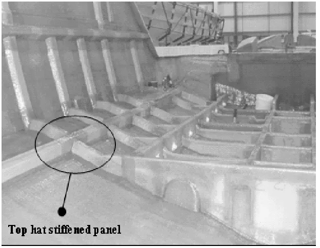
pas-senger ferries, lifeboats, minecountermeasure vessels and yachts. Typically the structural
styles of these FRP ships can be classified into four types:
• (type-1) Tophat stiffened single skin structure
• (type-2) Monocoque structure
• (type-3) Sandwich structure
• (type-4) Corrugated structure
Although each type has its own advantages and disadvantages which designers have to
consider, for all of these structural types un-/stiffened plates are the main components of
the hulls leading to a similarity in the initial design stage. Out of these structural styles,
type-1 should be an excellent design example. It is intensively used in ship construction
ber of hulls and ease of quality control. In the design of unstiffened plates, for example
Figure 1.1: Stiffened single skin structure
a laminate single skin, many design variables have to be considered, such as fibre
orien-tation, layer thickness, fibre types and so on. Furthermore, their failure modes, such as
strength degradation, buckling and delamination, also need to be taken into account.
Looking at stiffened plates, the number of design variables is higher so that a large design
space is inevitable. Examples of additional variables are section height, section width,
web angle and flange width, as well as web and crown layup. Moreover, the failure modes
of the plates are more complicated because of their complex geometry. For instance,
column buckling of stiffener/plate combination, shear buckling of webs and interlaminar
1.2
Motivation and research aim
As mentioned above, it is noticed that if the ship structure is designed to be for example
the strongest, lightest and cheapest, the design scheme is complicated due to issues such
as composite material design, production process, alternative lamination schemes and
al-ternative topologies. Hence, the design of composite ship structures can be considered to
be challenging research.
The aim of this work can be stated as follows: the optimisation methodology for
minimis-ing the weight of un-/stiffened laminated plates is introduced, implemented and proved
for its use in the initial design stage. The main advantage of the proposed methodology
Review of optimisation techniques
for structural design
2.1
Introduction
Since there are many aspects that must be considered in the design process of composite
structures, at the beginning of this chapter the definition of constituents, production
processes and manufacturing cost classifications are briefly described to remind the reader
of these fundamental concepts. Next, the marine applications of FRP are reviewed in order
to gain an understanding of how it is used in practice. Then ship design methods and their
limitations are explained. A literature review on ship design is also presented. As the
nature of the design problem is repeatable, optimisation techniques are commonly used
as a tool in the design process. Those optimisation techniques and their applications to
composite structures are reviewed and this could be a guideline in finding the appropriate
techniques for this work.
2.2
Background to FRP composites
A composite is a combination of one or more reinforcements with resin to produce a new
material having different material properties from their constituents. Therefore, one main
factor having influence on the composite properties is the selection of component
materi-als whose characteristics are illustrated as follows [111].
Resin is a material used to fasten reinforcements together. To ensure compatibility with
the fibre reinforcement, the resin should have the following properties:
1. The resin should be able to deform at least to the same extent as fibre when a
composite is loaded in tension.
2. The resin should transfer loads efficiently to prevent cracking or debonding,
3. The resin should have a high strain to failure property so that the composite is likely
to have a toughness property leading to high resistance in cracking propagation
4. The resin should be able to resist water or other aggressive substances in a marine
environment (e.g. fire conditions) and to withstand a constant stress cycling.
In the marine industry, there are three main types of resins, namely polyesters,
vinyl-esters and epoxies.
Polyesters are the most commonly used for marine structural applications because of their
low cost and ease of use in manufacturing processes. However, they provide only moderate
mechanical properties and in the open mould, styrene emissions are high during the
cur-ing process. High resin shrinkage between 5 to 8 % occurs durcur-ing cure. The workcur-ing life
(shelf-life) is limited to typically 6 to 12 months while pot life may be anything from a few
minutes to several hours depending on the room temperature and the quantity of catalyst.
Vinyl-esters have been used to a limited extent since they are expensive. Similar to
polyesters, high cure shrinkage and styrene emissions have been found during curing
pro-cess. Nevertheless, they provide a very high chemical/ environmental resistance and high
chanical and thermal properties, high water resistance, high temperature resistance and
long working times. However, they are the most expensive of the three types described.
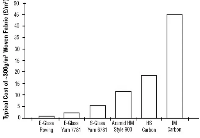
The reinforcement is typically in the form of fibres with significantly higher
mechani-cal properties than the resins. In marine application, the common fibres are E-glass,
S-glass, carbon and aramids. Because the characteristics of E-glass are high electrical
re-sistance, high strength and lowest cost related to the price of other fibre types (see Figure
[image:25.595.146.474.334.561.2]2.1), it is widely used in marine FRP construction. S-glass offers higher tensile strength
Figure 2.1: The comparative fibre cost
and better fatigue resistance than E-glass but S-glass is more expensive. Its application is
often found more in aerospace structure where high-performance composites are required.
Carbon fibres are available in a variety of strength-modulus characteristics. Two
typ-ical carbon fibres are high strength carbon (HS) and high modulus carbon (HM). HS is
of a higher production temperature. Since all carbon fibre types have relatively low
den-sity compared to E-glass, their application is found in the structures where weight saving
is a major design requirement.
The composite properties depend on not only the selected constituents but also
com-posite structural forms which can be expressed as follows:
Unidirectional lamina, where all fibres run in one direction only, is a basic form of
contin-uous fibre composite. Its stiffness and strength along the fibre direction are much greater
than those in the transverse direction. This composite form is rarely found in real
appli-cations but in the basic design stage of a large structure, generally it can be used as the
simplified model for complex composite forms.
Woven fabrics are produced by the interlacing of warp (0) fibre and weft (90) fibre in
a regular pattern or weave style (e.g. twill, plain weave, basket weave and satin). Hence,
a flexible fibre is suitable for this composite form. This composite form gives better
in-plane transverse properties than the unidirectional lamina.
The laminate forms are comprised of more than one unidirectional or woven lamina
ar-ranged with different fibre angles. The mechanical behaviours of this form strongly rely
on its stacking sequence. The applications example of this composite form can be found
in the structures of small crafts such as lifeboats.
A hybrid composite is a composite having more than one fibre type or a composite
combined with metal. This composite form gains benefits from the best combination
of different fibre types or from other material types.
Chopped strand mat (CSM) consists of randomly oriented chopped fibres which are held
sage of moisture through the membrane (or osmosis).
Another factor affecting the quality of a composite is the production method, such as
hand layup, spray layup, filament winding, pultrusion and so on. Out of these methods,
hand layup, the oldest method, is widely used because it is flexible, it requires little
cap-ital investment and prior knowledge, as well as being highly economical for prototypes
and short production series. Briefly the procedures of this method are that the fibre
mat is simply laid into an open mould by hand and resin is then applied with a brush.
After that, the laminate is rolled and allowed to cure under standard atmospheric pressure.
Spray layup was developed as an alternative to hand layup in order to raise the
pro-ductivity. Generally, chopped fibre and resin are simultaneously sprayed by spray gun
into the mould and the laminate is rolled. Although the cost of this method is lower than
hand layup, a lower composite quality is obtained.
Resin transfer moulding (RTM) is used to obtain a higher quality laminate and high
fibre volume fraction. RTM is the most common liquid moulding method and it is
capa-ble of producing large, complex and highly integrated components. Moreover, it combines
low capital cost, low mould cost with a quality work. In this process, the closed mould
is used with dry reinforcement and the mould can be closed in various ways. The low
viscosity liquid resin is injected into the mould by vacuum pressure.
Although the use of composites leads to many benefits, high manufacturing cost will
be faced for some applications. Therefore, this cost aspect is the major issue that the
designer must consider. Generally, the total cost consists of two parts: direct and indirect
cost. Direct cost is defined as the cost which directly attributes to the manufacture of
a specific product. These are the costs of materials and labour. For composite marine
needs high skilled labour and more complicated production facilities. Production cost
depends on many factors such as type of vessel constructed, production quantities and
shipyard efficiency. Table 2.1 shows a source of rough estimating data as it applies to
var-ious types of construction. It can be seen that the type of construction and application of
the ship can affect the work done and labour cost, for example the labour cost of single
skin with frames is higher than that of sandwich construction for a Scott fibreglass boat
[image:28.595.82.563.323.654.2]construction.
Table 2.1: Marine composite construction productivity rates from Eric Greene Associates Inc. (2001)
Source Type of Construction Application kg/hour∗ m2/hour⊙ hours/m2⊗
(lbs/hour) (f t2/hour) (hour/f t2)
Single skin with frames Recreational 9.07∗ 3.7⊙ 0.27⊗
(20) (33) (0.03)
Scott Military 5.44∗ 1.86⊙ 0.54⊗
fibreglass (12) (20) (0.05)
boat Sandwich Construction Recreational 4.54∗ 1.58⊙ 0.63⊗
construction (10) (17) (0.6)
Military 2.72∗ 0.93⊙ 1.08⊗
(6) (10) (10)
Single skin with frames Flat panel (Hull) 5.90∗∗ 2.04∗∗ 0.49∗∗
(13) (22) (0.05)
Stiffeners & Frames 2.27∗∗ 0.84∗∗ 1.19∗∗
(5) (9) (12)
BLA Core preparation for Flat panel (Hull) 11.79∗∗ 3.99∗∗ 0.25∗∗
combatant (26) (43) (0.02)
Feasibility sandwich construction Stiffeners 11.79∗∗ 3.99∗∗ 0.25∗∗
Study (26) (43) (0.02)
Vacuum assisted resin Flat panel (Hull) 4.54δ
3.99δ
0.25δ
(10) (43) (0.02)
Transfer molding (VARTM) Stiffeners 3.18δ
1.30δ
0.77δ
(7) (14) (0.07)
∗ Based on mat/woven roving laminate
∗∗ Based on one woven roving(WR) or unidirectional (UD) layer
⊙ Single ply of mat/woven roving laminate
⊗ Time to laminate one ply of mat/woven roving (reciprocal ofm2/hour(hour/f t2)) δ
In the early 1940s, small boats, such as canoes, speedboats, coastal yachts and lifeboats,
traditionally built of wood were firstly changed to use FRP as a result of their lower initial
and maintenance cost and more freedom in design. For luxury yachts or high-speed boats,
high cost carbon fibres are attractive because of their lightweight properties compared to
other fibre types. To avoid a serious unexpected failure from misused carbon fibre in
sailboats, Sponberge (1986) discussed the basic sailboat hull engineering and studied the
results of flexural as well as impact tests conducted on five different sandwiches.
For larger ships (e.g. cargo vessels, fast ferries and hovercraft), Smith (1990) concluded
that ships built of FRP are limited to ship lengths less than about 40 m since the smaller
the hull size, the cheaper the construction cost by comparison to those built of steel.
How-ever, due to the advance of manufacturing technologies and the demand for composite
ships at the present time, Mouritz et al. (2001) have predicted that ships up to 160 m
may be built from FRP by the year 2020. This prediction is supported by the trend curve
of the length of composite ships against the year of construction. To make this prediction
possible, the fabrication technology needs to be developed. Horsmon and Bernhard (2003)
for instance provided fabrication details with practical considerations for the production
of large composite vessels in an efficient and cost effective manner.
Mouritz et al. (2001) presented a detailed review on naval ships and submarines. It
has been mentioned that naval patrol boats are rarely built longer than about 20 m
be-cause of their low hull girder stiffness which is the main problem of building ships with
composite. This is backed up by the deflection estimation of hull girders of a 50 m long
composite vessel which is higher than that of steel vessels by about 240 % presented by
Alm (1983). However, this stiffness problem can be solved by using a sandwich structure.
For example, the Swedish Navy in the late 1980s built a 30 m long surface effect ship
known as the Smyge MPC2000, from sandwich composite materials. With these
against underwater shock loading, a number of stealth properties and good noise damping
properties.
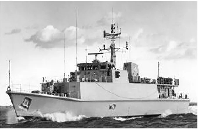
FRP is attractive to constructors of minecoutermeasure vessels (MCMV) because of the
need to have a low magnetic signature. In the late 1960s, a pioneering decision of using
FRP in place of wood was taken by the Royal Navy because the construction cost of
wooden vessels was higher (based on UK labour rates and material prices), wood hulls
require ongoing maintenance and FRP hull can resist explosive loads better than wooden
hulls, Smith (1990). To increase the hull girder stiffness, the MCMV is commonly built
of the framed single skin hull type. Example of MCMV is the Royal Navy’s Hunt and
[image:30.595.142.482.372.595.2]Sandown shown in Figure 2.2.
Figure 2.2: HMS Sandown
Submarines are built of FRP because of the high pressure and corrosion resistance as
well as the reduction of weight and magnetic signature. Tucker (1979) successfully built
ered submarine from composite material to achieve the highest strength to weight ratio.
In the past, to reduce the topside weight of ships, aluminium alloy have been used as
the building material for the superstructure while the ship hull is made of steel.
How-ever, aluminium alloy superstructures have poor fire resistance. Furthermore, due to the
dissimilarity of building materials, there is a widespread cracking between hull and
su-perstructure leading to expensive repairs. To overcome this, FRP has been recommended
to replace the aluminium because their tensile and compressive strength is close to mild
steel and FRP has a lower Young’s modulus than mild steel. This is likely to eliminate
fatigue failure induced by cyclic, wave-induced bending of the ship hull. An example of a
ship with a composite superstructure section for instance is the Lafayette frigate.
Composites have also found use in other applications. Marsh (2001) reported that
com-posite drive shafts are benefiting vessels ranging from lifeboats to cruise ships because of
their lighter weight, saving on complexity, resistance to corrosion, absorbing torque and
tolerating tensional shocks. Recently, a carbon fibre shaft, 23 m in length, was chosen for
use in an auto express catamaran built for Minoan High Speed Ferries. Another example
are propellers, traditionally made of high stiffness metal materials, which deform only
slightly and are usually designed to work at a constant speed, operating at reduced
effi-ciency at other speeds. To overcome this drawback, the composite propeller is introduced
which can deform to operate more efficiently at a variety of speeds. Lee and Lin (2004)
determined fibre orientation in a composite propeller to obtain the most efficient design.
2.4
Design methods
Ship design is usually described with the aid of the design spiral, which consists of three
types of constraints: direct constraints on the design, constraints on the design process and
inputting ship parameters, selecting machinery, calculating weight balance, checking
sea-keeping, calculating longitudinal strength and estimating cost, including life cycle costs.
It can be seen that the design of the ship structure is a part of the spiral. Due to the
scope of this work, the ship structural designs are described as follows.
Ship structural design can be achieved by: rule based design, first principle design or
stochastic method.
Rule base design, the oldest approach, is related to load consideration, strength and design
criteria from classification rules. It is easy to use when determining structural dimensions
of a ship and it helps to save time in the design office and approval process. However,
its simplified formulas cannot distinguish between structural adequacy and over-adequacy
and they can only be used within certain limits. Furthermore, the available classification
rules for ships built of FRP have their own standards and limitations. Lloyd’s Register
(LR) provides rules applying to ships less than 30 m length and the American Bureau of
Shipping (ABS) rules are limited to ships upto 50 m. Hence, if ship length exceeds the
scope of classification rules, first principle design (finding dimensions based on applying
structural theory directly) or stochastic methods are required.
First principle design consists of three parts: design load, structural response analysis
and strength assessment. The loads acting on a ship are such as still water global loads,
wave loads, local loads, external pressure loads, internal loads (liquid tanks/dry cargo)
and dynamic loads. For instance, the vertical load (qsv) of still water global loads can be
determined from the following equation:
qsv(x) =b(x)−w(x) (2.1)
where b(x) is the buoyancy force, w(x) is the weight of the ship and x is the distance
vided into three components: primary response (entire hull), secondary response (e.g.
stiffened panels, main deck and double bottom) and tertiary response (unstiffened plate).
At the initial design stage, the primary response is analysed when the ship bends as
a beam under the longitudinal distribution load. The formulas for this analysis are based
on beam theory. For example, the bending moment (M) at a cross section of a composite
beam can be found by Eq.3.16 in the next chapter.
To evaluate the secondary response, the theories reviewed in section 8.3.1 in Chapter
3 could be used, namely grillage analysis, equivalent orthotropic plate method (EOPM)
and folded plate method (FPM). For tertiary response, the uses of equivalent single
lam-inate theories (ESL) are possible. However, those theories are analytical methods which
could have a difficulty for complex geometry or structures subjected to various boundary
conditions. As a result of this, numerical methods such as the finite element method
(FEM) are often used to analyse those structures.
For the strength assessment part, ultimate bending moment, ultimate strength,
buck-ling, yielding, serviceability and ultimate limit states are considered. The occurance of
yielding, for example can be assessed by using the Von Mises yield criterion for steel ship
and composite failure criterion (e.g. Tsai-Wu, Tsai-Hill, Maximum stress criteria) for
composite ships.
The stochastic method is a design procedure based on a probabilistic model for loads
and strength. The output of this method is the required strength of the structure, which
can be derived from safety factors related to the calculation of the probability of failure
(Pf). Pf is calculated from a probability distribution function of all relevant quantities:
loads, load effects (e.g. hull girder bending moment) and limit values. Since the
values, arising from many separated variations (material properties, accuracy of analysis,
etc.) are not easy to obtain, this design method is less favoured compared to other
meth-ods.
To study the development in ship design, the following papers have been reviewed.
Op-timisation of ship structures is not a new concept.
Within the Transaction of RINA, Moe (1968) designed the longitudinal strength
mem-bers of tankers to gain their minimum cost and weight by the ’non-linear programming’
optimisation procedure. Subsequently, Fisher (1972) presented economic optimisation
procedures in preliminary design in which the “unconstrained minimisation” method of
Nelder and Mead (1965) was employed. Smith (1973) used non-linear programming to
minimise the weight of an oil tanker design. Watson (1976) considered how the
relation-ship between dimensions, the coefficients and approximate formulae of traditional naval
architecture had changed and their consequent improvement in ship design. With
fur-ther advances in computational power, the consideration that the design success of a
ship in operation is often based on more than one objective was applied by Sen (1992)
who proposed the “multiple criteria decision making” (MCDM) method and applied the
methodology to design various types of ship. From 1980’s to the present day, whilst
papers have been published on design philosophies and techniques and Andrews (1981),
Chalmers (1982), Frieze (1987), Keane (1988), Loukakis (1988) and Andrews (2003), there
have been few publications involved with design optimisation of ships and ship structures.
Furthermore, comprehensive reviews of ship design can be found in the proceedings of
the International Ship and Offshore Structures Congress (ISSC). The recent relevant
pa-pers from ISSC reports are presented below.
Hughes (1997) presented a strategy for achieving a first principles optimum structural
of aluminium and composite ships under the constraint of a strength criteria. The
struc-tural analysis depends on the Finite Element Method (FEM) which could lead to a high
computational time. The design variables are the structural scantlings (e.g. plate
thick-ness).
Rigo (2001) and Rigo and Fleury (2001) presented the development of LBR-5 (stiffened
panels software) which includes a new design methodology consisting of three basic
mod-ules: cost, constraint and optimisation. LBR-5 can be used for complex floating structures
generally comprising of stiffened cylindrical shells which are built of isotropic material
only. Design variables that can be dealt with are plate thickness, stiffener dimension and
stiffener spacing. Since the LBR-5 does not include a finite element analysis, it is fast in
obtaining the optimal solution.
Karr et. al. (2002) introduced a combination of three existing computer applications:
LBR-5, ISSMID-T (an integrated process/product model for the design of midship
sec-tions of tankers) and virtual reality simulasec-tions as a generic design methodology for
sim-ulation based ship design. The example application is performed on the midship section
of a double hull cargo vessel.
Moreover based on the ISSC reports, it has been found that many papers present only
the applications of ship structural design software and the improvement in capability of
these software. It is therefore apparent that there is a lack of published research into
frameworks for optimising composite ship structure.
2.5
Development of optimisation techniques
Optimisation is the act of obtaining the best results under given circumstances. Over one
For engineering, it is very important because designers have to take many technical and
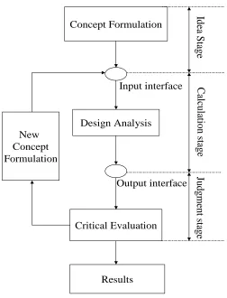
managerial decisions in several stages. To help the designer, nowadays computers are
commonly used as a design tool. Figure 2.3 shows a general example of how designers
and computers work together.
Concept Formulation
Design Analysis
Critical Evaluation New
Concept Formulation
Results
Judg
m
ent
s
ta
g
e
C
al
cul
at
ion s
ta
g
e
Id
ea
S
ta
ge
Input interface
[image:36.595.183.435.218.548.2]Output interface
Figure 2.3: Design decision process
In the idea stage, designers consider concept formulations and construct optimisation
functions. In the calculation stage, these functions are implemented in a program by
which the computer calculates the results. The judgment stage is that if these results
do not satisfy their requirements, a new design formulation process is started. From the
design decision process, it can be seen that the nature of design procedure is iterative and
Objective functions: minimise or maximise f(x)
Constraints: equality constraints hj(x) = 0 and/or inequalities constraints gk(x)>0
Design variable: x= [x1, x2, ..., xn]T
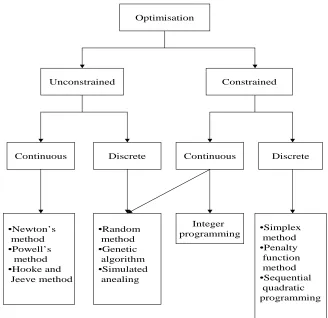
To solve the optimisation problem, there are numerous optimisation techniques
avail-able, which can be classified based on the existence of constraints and the nature of the
design variables as shown in Figure 2.4.
Optimisation
Unconstrained Constrained
Continuous Discrete Continuous Discrete
•Newton’s method •Powell’s
method •Hooke and
Jeeve method
•Random method •Genetic
algorithm •Simulated
anealing
Integer
programming •Simplex method
•Penalty function method •Sequential
[image:37.595.147.475.311.629.2]quadratic programming
The developments of these techniques begin with unconstrained class. The oldest
tech-nique is based on differential calculus that was firstly introduced by Newton and/or
Leib-niz during the later part of the 17th century (Manoha (1993)). It is limited to only
an unconstrained problem related to min-max condition of calculus. Similarly, Newton’s
method is introduced by using the first few terms of a series expansion of a function about
a point (Taylor series expansion). The unconstrained optimisation methods could be also
divided into two groups: methods involved with derivative (Steepest descent method,
Fletcher-Reeves method, etc.) and methods without derivative (Powell’s method, Hooke
and Jeeves method, etc.).
To deal with constrained problems, the simplex technique is devised by George B.
Dantz-ing in late 1940s for problems havDantz-ing linear objectives and constraints, which could be
in forms of equalities and inequalities. If the number of design variables is small, the
problem could be solved by drawing graphs. Otherwise, it can be solved in tableau form
or by a computer program.
For non-linear constrained problems, the earliest development was the extension of
sim-ple min-max conditions by using the formulation of augmented Lagrangian multipliers,
which are based on variational methods. This leads to numerous difficulties in practical
applications as a result of non-linear differential equation.
Kelly (1961) presented the cutting plane technique which can solve a problem having
linear objectives and nonlinear constraints. The algorithm of this technique involves
solv-ing a sequence of linear programmsolv-ing and nonlinear constraints, which are linearised by
using a Taylor’s series in the following form.
gj(x)≈gj(t) +∇gj(t)T(x−t) (2.2)
where t is an arbitrary point and x is a set of design variables. Then all functions are
To solve the problem of nonlinear objectives with a variety of types of constraints, Rosen
(1960) presented the gradient projection technique. Its main idea is choosing a feasible
starting point and moving to a better point based on the modified gradient of the
ob-jective function in the iterative scheme. The modified gradient is implemented by the
normalised search direction (Si) as shown in the following equation:
Si = −
Pi∇f(xi)
k−Pi∇f(xi)k
(2.3)
wherePi is the projection matrix. The new approximated point for iteration is related to
bothSi and the vector of the Lagrangian multiplier.
Box (1965) extended the simplex technique of unconstrained minimisation to solve
con-strained minimisation problems by comparing the values of the objective function at the
(n+1) vertices (corners) of a general simplex and moving the simplex gradually towards
the optimum point during the iterative process. This technique firstly generates points
that individually satisfy the side constraints and then checks whether each point satisfies
all other constraints. It is noted that this technique is simple in computation and does
not require large computer storage as none of the derivatives are required. However, if
the feasible region is non-convex, there is no guarantee of convergence.
From the benefit of using unconstrained optimisation techniques, which have simpler
al-gorithms, the idea of transforming constrained problems to unconstrained ones has been
proposed. For simple problems, the intervals of design variables can be substituted into
objective functions to become unconstrained problems. For more complex problems, a
Carroll (1961) set up the interior penalty function by the following formulation,
φ(x, rk) =f(x)−rk m
X
j=1
1
gj(x)
(2.4)
where (rk) is the penalty parameter. This technique produces subsequent points lying
inside the acceptable region of the design space.
Fiacco and McCormick (1967) presented a form of the exterior penalty function which is,
φ(x, rk, t) =f(x)−r−k1 m
X
j=1
[gj(x)−ti]2 (2.5)
wheret is non-negative for a strictly decreasing penalty parameter (rk). Unlike the
inte-rior penalty technique, this technique generates a non-feasible sequence of unconstrained
minimum points that may yield a feasible solution. Its convergence starts from the
infea-sible region.
At the present, Sequential Quadratic Programming (SQP) techniques developed in the
1970s are probably the most effective optimisation technique for the nonlinear constrained
problems since the principle of SQP is transforming the problems into an easier
subprob-lem that can be solved by a basic iterative process.
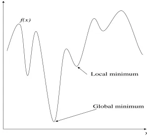
All techniques mentioned above are based on mathematical programming, which require
calculus or a relation between points in a design space. Because of this, some of them
are limited to a continuous design space. Moreover, all of them are almost assured of
locating the relative optimum closest to the starting points so that for a design space
having multiple optima as shown in Figure 2.5, they may provide the local optimum if
Global minimum
x y
Local minimum
[image:41.595.166.463.141.421.2]f(x)
Figure 2.5: Global and local minimum of the multiple-peak function
The category of stochastic search techniques such as Simulated Annealing (SA) and
Ge-netic Algorithm (GA) can overcome this drawback of mathematical programming
tech-niques. They have been growing rapidly in popularity over the last one or two decade.
SA proposed by Metropolise et al. (1953) is derived from a simulation of behaviour of
particles in thermal equilibrium at a specific temperature. GA is more popular than SA
in structural optimisation. GA was firstly developed by Holland (1975). Its search
al-gorithm mimics the mechanics of natural selection and natural genetics. A general form
of GA sexual reproduction consists of an initialisation of the populations, fitness
evalu-ation, selecting members of population and genetic operators. Because GAs work with
a coding solution set, searching from a population of solutions, using fitness functions
mathematical programming techniques. It is easily implemented because it is only
neces-sary to change the chromosome to solve other problems using the same basic algorithm.
However, it is difficult to encode design variables and to find the value of the fitness
function.
2.6
Applications of optimisation techniques to
com-posite structures
The optimisation formulations for the design of composite laminates lead to non-linear
functions of the number of plies, lamina thickness and fibre orientation. Traditionally,
these design variables are defined as real numbers, which can be solved by gradient-based
techniques. Hirano (1979) used Powell’s technique (conjugate direct technique) to find
the optimum lamina fibre angle of laminated plates for maximum critical buckling stress,
which is based on a closed form solution. Schmit and Mehrinfar (1982) proposed
multi-level optimum design of structures with fibre-composite stiffened panel components, where
weight minimisation is the objective and local buckling displacement and strength are the
constraints. Inside the optimisation scheme, a sequence of unconstrained problems are
solved by a modified Newton technique. Soares et al. (1995) presented the two level
optimisation for thin shell composite structures. At the first level, which is defined as
an unconstrained problem, the Davidon-Fletcher-Powell variable metric technique, that
minimises the displacement of the structures, is used to find the fibre direction of each
ply. At the second level where the problem is a constrained problem (minimising the
volume of material subject to constraints of maximum displacement of nodal points in
the FEA model, Tsai-Hill failure criterion and/or the natural frequency), the modified
feasible directions technique is employed. Again, Powell’s technique was used by Moh
and Hwu (1997) to design composite sandwich plates. The highest critical buckling load
is required which is controlled by the fibre orientations of the face laminas. Kim et al.
ria. Walkeret al. (1997) designed symmetrically laminated plates to obtain the minimum
deflection and weight by using the golden section technique based on the finite element
formulation with the Tsai-Wu criterion as a constraint. Bruyneel and Fleury (2002)
intro-duced the approximation concept to solve the optimisation of composite structures when
both plies thickness and fibre orientations are considered as design variables to find the
highest stiffness structure. The papers mentioned above provide similar conclusions; the
classical optimisation techniques get trapped at local optima and the optimum fibre angle
is a real number, which is not suitable for manufacturing processes.
Recently, the evolutionary optimisations (SA or GA) are more popular in the design
of composite structures because they are based on random processes, which are used to
set the direction of better searching and they can store and use information from previous
results. Sciuvaet al. (2003) used SA for multi-constrained optimisation of laminated and
sandwich plates. The maximum buckling load and minimum mass are the objectives and
transverse stiffness, mass and frequencies are the constraints. Fibre orientation is the
de-sign variable. Laminated plate theories are used for structural analysis. For this particular
problem, it has been concluded that SA provides better results than GA. However, there
is no other research to confirm that SA is better than GA or a test with both techniques in
other optimisation problems of composite structures. Moreover, the application of SA on
composite structural design is rare since GA is more popular than SA due to its simplicity.
Riche and Haftka (1993) presented the use of GA to optimise the stacking sequence of a
composite laminate for maximum buckling load, which is calculated from a closed form
solution subjected to strain failure constraints. Sivakumar et al. (1998) successfully
ap-plied GA and FEA related to FSDT to a laminate with an elliptical hole. Three examples
of applications are presented and their objectives are such as maximising fundamental
frequency, maximising first and second natural frequency, and weight minimisation.
there is a possibility that the optimum point may not lie in the decoded values within
the chosen string. Hence care should be taken for deciding the string length such that
the variables are well distributed within the prescribed bounds. Parket al. (2001) used a
GA to find the optimal stacking sequence of laminated composites under various loading
and boundary conditions, optimised for maximum strength concerned with Tsai-Hill
fail-ure criterion. The plate stresses are calculated by FEA derived from FSDT. The design
variable is ply orientation. Muc and Gurba (2001) emphasis the excellent feature of a
GA in that it does not require any sensitivity analysis and therefore propose the use of
GA incorporated into a FEA package for the optimisation of composite structures with
regard to stacking sequence, shape and sizing. This could be applied to problems with
un-constrained optimisation formulations. To find the optimum fibre orientation, maximum
buckling load is set as the objective. To find the optimum shape and sizing, maximum
strength of the structures in combination with an assumed failure criterion is the
objec-tive. Parket al. (2003) designed laminated plates to obtain the optimum fibre angle for
weight minimisation under stiffness and mould filling time requirements by using a GA
combined with a finite element calculation program (FEAD-LASP).
Only a few researchers have combined multi-objective design with GA. Walker and Smith
(2003) introduced the use of GAs together with a multi-objective approach and the FEM
for the design optimisation of symmetrically laminated plates to minimise both mass and
deflection. Costaet al. (2004) used a multi-objective GA to tackle the differentiable and
convex problem. The multiple-objectives were cost, mass, thickness and compliance of a
laminate plate. Structural analysis formulations were based on FEA. Deka et al. (2005)
firstly presented multi-objective optimisation of hybrid composite laminates by using GA
and FEA. The objectives of the problem were weight and cost which were given equal
importance. The design variable was the stacking sequence. Due to less research
involv-ing optimal design of laminated plates under various loads, Kim and Lee (2005) designed
symmetrically laminated composite plates under uniaxial compression, shear, biaxial and
Much research deals with the application of GAs to unstiffened laminate composites.
On the other hand, GA based optimisation concerned with stiffened plates is less
com-mon in the literature. Bisagni and Lanzi (2002) used a combination of a GA and neural
networks as optimisation tools and FEA for structural analysis to design composite plates
stiffened in one direction for minimum weight subjected to buckling load, collapse load
and the pre-buckling stiffness. Kang and Kim (2005) designed unstiffened and
unidirec-tionally stiffened composite plates by using GA with COSAP (non-linear finite element
code) to obtain minimum weight under constrained post buckling strength.
Several studies have concentrated on improving the reliability and efficiency of GAs in
applications to optimise laminate structures. Nagendraet al. (1996) presented the
inves-tigations of the effect of various modifications (focus on GA operators) to basic GA for the
minimum weight design of stiffened panels subjected to stability and strain constraints.
The improved GA reduced the weight of the plates by about 4 %. Soremekunet al. (2001)
suggested incorporating a generalised elitism selection into a standard GA. The improved
GA is applied to two problems: buckling load maximisation of simply supported
lami-nated plates and twist angle maximisation of cantilever-lamilami-nated plates. The fibre angle
is set as the design variable. Gantovik et al. (2002) introduced a suitable algorithm for
GAs with memory that can work with both discrete and continuous variables
simultane-ously and can be used for weight minimisation of laminated sandwich plates subjected to
strength and buckling constraints based on closed form solutions. The use of the memory
and spline approximation for a continuous variable avoids repeating analyses of previously
encountered designs. Rahulet al. (2005) employed the combination of GA with a parallel
computing environment (called IMPGA) and FEM for hybrid laminates under transverse
impact loading. Three types of optimisation problem have been considered namely cost
minimisation, weight minimisation and combined cost weight minimisation. The design
the optimisation scheme to have low communication with the GA.
2.7
Summary
According to the literature review of ship design in section 2.4, all optimisation methods
have considered only traditional structural materials of steel and aluminium.
Optimisa-tion of FRP structures has not been applied explicitly to ship structural topologies.
Optimisation methods have been reviewed from classical to modern methods as well as
their applications to composite structural design problems. The comparison of
charac-teristics of some optimisation techniques is presented in Table 2.2. Moreover, the points
below can be drawn:
• Classical methods such as Newton’s method, Box method and so on are concerned with the differentiation or relation between points in a design space. Their
applica-tions to composite structural design problems show that the optimum fibre angles
are real numbers which are unsuitable for manufacturing process because the
typ-ical fibre angle in layup process are such as 0◦ , 45◦
and 90◦
. Moreover, the global
optimum could not be obtained because classical optimization methods provide the
nearest point satisfying the optimum condition which is, for example, the slope at
the point equal to zero.
• The composite structural design problem has a design space that may be non-linear, discontinuous and fluctuating. Hence, the use of stochastic optimisation methods is
more appropriate than that of classical methods because they rely on probabilistic
transition rules. Out of those, the most popular method is GA, which has been
successfully used by many researchers.
• There are many papers involving the optimisation of unstiffened laminated plates using GAs but few papers involved with the use of GA with stiffened plates.
Table 2.2: Characteristics of optimisation techniques
Techniques Objective Constraint Variables Starting
point Convergence Complex techniques linear or nonlinear linear or nonlinear in-equality but cannot be equality
continuous feasible by searching. inefficient
for large number of
vari-ables and no guarantee
to converge for nonconvex
problems SUMT (interior) linear or nonlinear linear or nonlinear
continuous feasible using derivative
SQP linear or
nonlinear
linear or
nonlinear
continuous feasible or
infeasible using derivative GA standard linear or nonlinear linear or nonlinear continuous or discrete feasible or infeasible
using stochastic searching
GA+ Based derivative method linear or nonlinear linear or nonlinear
continuous feasible or
infeasible
using stochastic searching.
(conven-tional method help to
Review of structural solutions for
FRP composite plates
3.1
Introduction
Before reviewing the structural analysis methods, the understanding of fundamental
knowledge of laminate mechanics is vital and this is summarised in the first section.
The literature review of these methods, is divided into two main parts: analytical and
numerical methods. Their advantages and disadvantages will be presented in summary
at the end of this chapter.
3.2
Background to FRP composite mechanics
The background of composite laminate theory is described as it is fundamental to the
understanding of structural and failure analyses of composite structures. Firstly, the
stress components (σij) can be defined on three perpendicular planes as shown in Figure
3.1. These linear stress tensors σij can be determined based on Hook’s law and can be
expressed as,
σij =Qijklǫkl (3.1)
x1 x2 x3 11
σ
13σ
12σ
σ
2123
σ
22
σ
31σ
σ
3233
σ
Figure 3.1: Stress components
whereσij and ǫkl are the second-order stress and strain tensors respectively, Qijkl are the
fourth-order elasticity tensors and (i, j, k, l = 1,2,3). To present Qijkl in compact form,
it is convenient to introduce a contracted notation, shown in table 3.1.
By the symmetric properties of materials Eq. 3.1 can be written in the form of
ten-sor notation as,
σ1 σ2 σ3 σ4 σ5 σ6 =
Q11 Q12 Q13 Q14 Q15 Q16
Q22 Q23 Q24 Q25 Q26
Q33 Q34 Q35 Q36
Q44 Q45 Q46
Q55 Q56
Sym. Q66
Table 3.1: The contracted notation
Strains Stresses
Tensor notations New notations Tensor notations New notations
ǫ11 ǫ1 σ11 σ1
ǫ22 ǫ2 σ22 σ2
ǫ33 ǫ3 σ33 σ3
2ǫ23=γ23 ǫ4 σ23=τ23 σ4
2ǫ13=γ13 ǫ5 σ13=τ13 σ5
2ǫ12=γ12 ǫ6 σ12=τ12 σ6
In the case of a two-dimensional space (for example, this is the assumption for the analysis
of thin plates) all the terms related to the x3 axis in the previous equations can be
neglected; the stress-strain relations can be simplified as follows:
σ1 σ2 σ6 =
Q11 Q12 0
Q12 Q22 0
0 0 Q66
ǫ1 ǫ2 ǫ6 (3.3)
For this 2D consideration, the constitutive relation is,
ǫ1 ǫ2 ǫ6 = 1
E11 − v12 E11 0
−v12 E11
1
E22 0 0 0 G112
σ1 σ2 σ6 (3.4)
whereEij andvij are Young’s modulus and Poisson’s ratio respectively. Thus, by inverting
Eq.3.4 and then comparing with Eq. 3.3, the compliance tensors can be expressed as,
Q11 =
E11
(1−v12E22/E11)
, Q12=
v12E12
(1−v12E22/E11)
(3.5)
Q22=
E22
(1−v12E22/E11)
, Q66=G12 (3.6)
To transform stresses from global axes (x-y plane) to local axes (L-T plane) Figure 3.2,
x
σ
yσ
xyσ
θ
x y L TFigure 3.2: An orthotropic lamina with its principal material axes arbitrary orientated with respect to reference co-ordinate axes
The equilibrium equation for L-, T- and LT-directions are presented as,
σL =σxcos2θ+σysin2θ+σxy(2sinθcosθ) (3.7)
σT =σxsin2θ+σycos2θ−σxy(2sinθcosθ) (3.8)
σLT =−σx(sinθcosθ) +σy(sinθcosθ) +σxy(cos2θ−sin2θ) (3.9)
These three equations can be represented in matrix form,
σL σT σLT
= [T]
σx σy σxy
, [T] =
cos2θ sin2θ 2sinθcosθ
sin2θ cos2θ −2sinθcosθ
−sinθcosθ sinθcosθ (cos2θ−sin2θ)