A study of tape spring fold curvature for space deployable
structures
S J I Walker∗andG S Aglietti
Astronautics Research Group, School of Engineering Sciences, University of Southampton, Highfield, Southampton, UK
The manuscript was received on 10 February 2007 and was accepted after revision for publication on 16 March 2007.
DOI: 10.1243/09544100JAERO209
Abstract: Tape springs, defined as thin metallic strips with an initially curved cross-section, are an attractive structural solution and hinge mechanism for small satellite deployable structures because of their low mass, low cost, and general simplicity. They have previously been used to deploy booms and array panels in various configurations that incorporate a two-dimensional deployment of the tape. However, applications currently exist that incorporate three-dimensional tape springs folds. To accurately model the deployment of an appendage mounted with tape spring hinges, it is necessary to accurately model the opening moments produced from the material strains in the tape spring fold. These moments are primarily a function of curvature. This publication uses a photographic method to analyse the curvature assumptions of two-dimensional tape spring folds and to define the curvature trends for three-two-dimensional tape spring folds as a basis for calculating the opening moment. It is found that although a variation in the curvature can be seen for three-dimensional tape spring folds, its effect is secondary to the tape thickness tolerance. Therefore, constant curvature models are concluded to be accurate enough for general tape fold applications.
Keywords: tape spring, curvature, three-dimensional fold, deployable structures
1 INTRODUCTION
Over recent decades there has been growing research and development in the miniaturization of electronic and mechanical technologies [1]. It is now possi-ble to construct very small satellites [2], thereby dramatically reducing the cost of access to space. However, in order to produce efficient and reliable small satellite deployable structures, new technolo-gies need to be developed. A scale reduction of larger systems does not result in efficient designs because of the inherent complexity of small mech-anisms and electric motors. One attractive structural solution is tape springs (more commonly known as carpenter tape). Tape springs are generally defined as thin metallic strips with a curved cross-section.
∗Corresponding author: Astronautics Research Group, School
of Engineering Sciences, University of Southampton, Highfield, Southampton SO17 1BJ, UK. email: [email protected]
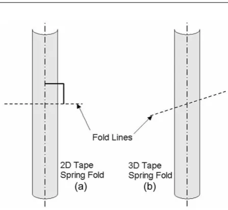
They have the key property that they are contin-uous (i.e. contain no mechanical hinges or other folding devices) and yet they can still be folded elastically. Therefore, they require no moving parts, lubrication, or locking devices and once deployed have good structural properties. Tape springs have recently been incorporated into various hinge designs such as the tape spring rolling hinges developed at the Deployable Structures Laboratory in the UK [3] and the three tape hinge developed by the French company Metravib [4]. These designs incorporate tape springs folded in two-dimensions (where the fold line is perpendicular to the lengthwise direc-tion, Fig. 1(a)). However, new deployment designs are under development that incorporates three-dimensional tape spring folds (where the fold line does not remain perpendicular to the lengthwise direction, Fig. 1(b)).
Fig. 1 Fold lines overlaid on a tape spring
the fold [5]. Therefore, to accurately model the open-ing moment the relationship between the fold angle and the fold curvature needs to be investigated.
2 BACKGROUND
Before the curvature investigation can be discussed it is first necessary to introduce some general properties of tape springs, both statically and when subjected to applied moments. The general coordinate system used throughout this study is shown in Fig. 2(a). The x-axis is defined as running along the longitudinal length of the tape spring, they-axis lies horizontally in the sectional plane of the tape spring and thez-axis is perpendicular to the flat plane of the strip.
The standard tape spring geometry for theoretical analysis is defined by four initial parameters (three in the sectional plane and one defining the length).
Fig. 2 General tape spring coordinate system and parameters
These can be seen in Figs 2(b) and (c). When a tape spring is subjected to two equal and opposite applied moments M (acting about the y-direction), the tape spring initially deflects, then buckles to form a localised fold as shown in Fig. 3(a).
Depending on the direction of the applied moments, the tape spring will buckle producing a lon-gitudinal radius of curvature either on the same side, or the opposing side to the initial transverse radius of curvature. These folds are known as two-dimensional equal and opposite sense bends, respectively. The general relationship between M and θ can be seen in Fig. 3(b), where opposite and equal sense buckling occurs at points A and B, respectively.
The general sign convention for this relationship is that a positive moment (M)produces an opposite sense bend [6]. Therefore, Fig. 3(a) displays positive moments and a rotational displacement in the posi-tive direction ofθ(forming an opposite sense bend).
[image:2.595.43.267.72.278.2] [image:2.595.300.540.75.260.2] [image:2.595.115.463.560.739.2]From Fig. 3(b) it should be noted that there are four key moment values identified for two-dimensional bends. These are the peak buckling moments,Mmax
+ andMmax
− , for opposite and equal sense bends, respec-tively, and the post buckling moments (known as steady-state moments) M+∗ and M−∗, for opposite and equal sense bends, respectively. When the peak moments are studied, it is found that opposite sense bends buckle via a snap through mode, whereas equal sense bends buckle via a torsional mode [7]. This results in higher peak moment magnitudes for opposite sense bends than for equal sense bends.
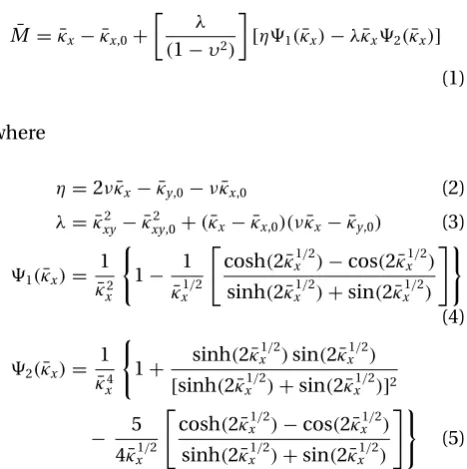
The analytical method for determining the open-ing moment,M, is based on traditional shell theory, which over the years has been used in a wide variety of applications [8]. For two-dimensional bending of tape springs the theory has been used to predict the steady-state and peak moments of the moment–rotation relationship (shown in Fig. 3(b)). The equation has previously been derived in various forms. However, in order to avoid indeterminate expressions within the equation, it is preferable to use the form that incorpo-rates non-dimensional parameters. In this form the equation becomes [5]
¯
M = ¯κx− ¯κx,0+
λ (1−υ2)
[η1(κ¯x)−λκ¯x2(κ¯x)]
(1)
where
η=2νκ¯x− ¯κy,0−νκ¯x,0 (2)
λ= ¯κxy2 − ¯κxy2,0+(κ¯x− ¯κx,0)(νκ¯x− ¯κy,0) (3)
1(κ¯x)= 1
¯
κ2
x
1− 1
¯
κx1/2
cosh(2κ¯x1/2)−cos(2κ¯x1/2) sinh(2κ¯x1/2)+sin(2κ¯x1/2)
(4)
2(κ¯x)= 1
¯
κ4
x
1+ sinh(2κ¯ 1/2
x )sin(2κ¯x1/2)
[sinh(2κ¯x1/2)+sin(2κ¯x1/2)]2
− 5
4κ¯x1/2
cosh(2κ¯x1/2)−cos(2κ¯x1/2) sinh(2κ¯x1/2)+sin(2κ¯x1/2)
(5)
The surface curvature in these equations is defined byκx,κy, andκxy. These parameters are the final lon-gitudinal, transverse and twisting curvature respec-tively. The corresponding initial curvatures of the surface are denoted by κx,0, κy,0, and κxy,0. All the non-dimensional parameters are denoted with a bar. The non-dimensional moment and curvatures are determined from
¯
M =
3a[3(1−ν2)]1/2
Et4 M (6)
and
{¯κx,0,κ¯xy,0,κ¯y,0,κ¯x,κ¯xy} =
a2[3(1−ν2)]1/2 4t
× {κx,0,κxy,0,κy,0,κx,κxy} (7)
whereaandt denotes the width of the undeformed tape and the tape thickness, respectively.
From these equations it can be seen that the open-ing moment is determined primarily as a function of the longitudinal curvature of the tape. Simplified theories [6] have used the assumption that the post-buckling curvatureκxof the tape is constant and equal to the initial transverse curvature,κy,0, i.e. the radius of curvature of the tape fold is equal to the initial radius of curvature of the tape section. To correctly apply this equation it is therefore necessary to investi-gate and justify this assumption. However, before this curvature study could be performed it was first neces-sary to accurately determine the sectional curvature properties of the tape sample.
3 DETERMINING THE CROSS-SECTIONAL CURVATURE
Experimental tests were performed on various lengths of uncoated tape all originating from the same tape roll. A short sample of the tape is shown in Fig. 4(a) and a diagram of the tape cross-section is displayed in Fig. 4(b).
It is clear from this figure that the material has not been yielded to form a constant radius arc. This is typical for tape springs purchased ‘off the shelf’. To accurately determine the centre curvature of the section, it was photographed with a digital camera and overlaid with constant radius arcs. Scale mark-ers were placed next to the point of interest in the photograph to verify the size of the image. To ensure the optics of the camera was accurate enough for these experiments, some constant radius arcs and ellipses of known proportions were photographed and printed. All dimensions were accurate to within 1 per cent. As this photographic method studies the
[image:3.595.61.295.391.626.2]Fig. 5 Tape section curvature overlay
curvature of the tape end, the data can be inac-curate if the sectional parameters of the tape end are not representative of the central cross-section of the sample. For example, some damage may occur when the samples are cut from the original roll of tape. However, any significant cross-sectional dam-age can generally be found by a visual inspection of the specimen.
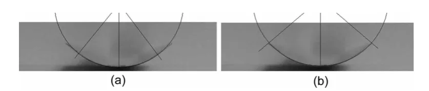
Fig. 5(a) shows the cross-section overlaid with a constant radius arc to determine the centre curva-ture of the section. This method calculated the radius of curvature (Ry)and the angle of embrace (α) of the centre section to be 14.18 mm and 1.309 rad, respec-tively. The centre curvature of this section is, therefore, taken as 0.071 mm−1, which in turn results in a cal-culated flat width of 4 mm either side of the central curvature.
To calculate the steady-state moment of a tape spring fold using the previous equations a curva-ture value for the whole section has to be used. To determine a constant radius arc approximation of the whole section, a larger circular arc is overlaid on the tape image as shown in Fig. 5(b). Although the tape has flat edges it can be seen that the constant radius arc approximation closely matches the true cross-section. There is no significant variation in the height or width of the section and only minor discrepancies along the transition of curvature. This constant radius arc approximation has a radius of curvature and an angle of embrace of 15.37 mm and 1.719 rad, respec-tively. Therefore, the initial transverse curvature of the tape was calculated to be 0.065 mm−1.
The impact of the constant radius arc approxima-tion was investigated using finite-element models in ABAQUS [9]. It was found that the constant radius arc approximation did affect the peak moment magni-tude resulting in an 11 per cent drop and a 6 per cent rise in the peak moments for opposite and equal sense bends, respectively. This is because of the slight cur-vature reduction of the section. However, it had little impact on the steady-state moment magnitudes, as the width of the flattened section at the fold location is the same.
A summary of all the experimental sample parameters is shown in Table 1. More information regarding the source of this data can be found in Walker [10].
Table 1 Tape spring properties
E 195.3×10³N/mm2
Ry 15.37 mm
α 1.719 rad
κy,0 0.065 mm−1
t 0.106 68−0.122 50 mm
σyield 1190 MPa
4 TWO-DIMENSIONAL TAPE CURVATURE INVESTIGATION
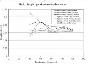
In order to investigate the bending curvature of the tape, folds were photographed along with a scale marker and overlaid with constant radius arcs. Both fold directions were analysed at five and six different bend angles for equal and opposite sense bends, respectively. Two curvature measurements were required as the curvature of the tape along the centre-line can vary significantly to the curvature of the tape along the edges. This was especially notice-able at low bend angles because of the close proximity of the transition regions [7] of the tape to the centre of the fold (Fig. 6). The transition regions are the lengths of tape over which the transverse curvature changes from the flat fold state to the initial transverse curva-ture state at a distance from the fold point. Circular curves were therefore overlaid to match the curvature at both the centre and the edges of the tape section (defined as ‘inner’ and ‘outer’ curvatures, respectively) to determine the maximum and minimum curva-ture at the fold. These two values were averaged to give a single curvature value for use in the theo-retical equations. A sample curvature photograph is displayed in Fig. 6 and the resultant curvatures can be seen in Fig. 7 plotted with the initial transverse curvature of the tape. The data points are overlaid with interpolated curves to improve the clarity of the figure.
[image:4.595.76.495.80.169.2]Fig. 6 Sample opposite sense bend curvature
Fig. 7 Curvature graph for two-dimensional tape spring fold
are therefore relatively easy to determine. This trend can also be seen in the data as the curvature variation between inner and outer curvatures reduces at higher bend angles. The low bend angles were simulated as closely as possible resulting in a trend of reduc-ing curvature before ‘snap back’ (not displayed in Fig. 7).
In the analysis of equal sense bends the inner cur-vatures and outer curcur-vatures simulate the tape edge and the centre, respectively. This is the reverse of the opposite sense curvature study. From the data it can be seen that there is a general trend of reducing curvature as the bend angle increases. The high cur-vatures at the low bend angle are primarily because of sharp curvatures at the tape edges. As in the oppo-site sense bend analysis, the higher the bend angle the larger the circumference of the flat region at the fold, the easier the curvature is to model. However, in contrast to opposite sense bends, high angle equal sense bends do not accurately simulate a uniform radius arc. Instead they tend to conform to a profile displayed in Fig. 8.
Fig. 8 The profile of a high angle equal sense bend
The middle flat region of the fold follows a smooth curvature, however, sharp folds can be found at points A and B as the cross-section starts to return to the initial transverse curvature. This primarily occurs at the edges of the tape. However, it also impacts the central region of the tape, increasing the inaccuracy of a constant radius arc approximation. This contributes to the fluctuation of the curvature as the bend angle changes.
[image:5.595.122.498.91.207.2] [image:5.595.130.505.204.474.2]variation of results. However, with increasing bend angle the curvature approaches κy,0. It can be seen that the opposite and equal sense bend curvatures tend to be less than and greater thanκy,0, respectively. The fundamental conclusion of this analysis is that the curvature does not increase with the bend angleθ. The assumption of constant curvature is closer to the real situation. Asκy,0is centrally located between the bend curvatures, it is a good single approximation for all bending results. This assumption of constant cur-vature equating toκy,0will therefore provide a basis for further analytical studies.
5 THREE-DIMENSIONAL TAPE CURVATURE INVESTIGATION
5.1 Theoretical background
From analytical studies of three-dimensional surface curvatures it is known that a three-dimensional sur-face can be defined by two lines of principal curvature, which are perpendicular to each other [11]. These are the lines of maximum and minimum curvature of the surface. A clear example of this is a local-ized two-dimensional tape spring fold as shown in Fig. 9(a), where the principal curvature values always refer to the centre of the fold. Mathematically, it can be demonstrated that if an equal and opposite twist angle is applied each side of the tape spring fold then the lines of principal curvature rotate as displayed in Fig. 9(b). The angle of this rotation is denoted byφ
and the relative twist angle between the tape ends is denoted byγ.
This torsional moment,Tcan be modelled using an equivalent equation to equation (1) [5], where
¯
T = ¯κxy− ¯κxy,0+
λκ¯xy1(κ¯x)
1−ν (8)
and
¯
T =
3a[3(1−ν2)]1/2
4Gt4 T (9)
Fig. 9 Lines of principle curvature
The combination of bending and twist of a tape sur-face can simulate any tape spring fold. However, it is important to establish that the analysis of this system does not directly produce the opening moment about an angled fold line, as shown in Fig. 1(b), defined as the hinge momentMHof a skew mounted tape spring. This analysis studies the bend and twisting of the tape surface in one plane defined as the theoretical plane [10]. This is displayed in Fig. 10. It is therefore impor-tant to determine the curvature of the fold in this plane as this is the input to determineMandT, from whichMHcan subsequently be found [12].
The tape fold curvatures used in the theoretical models are all elements of the curvature matrix for the surface as shown in equation (10) (where for this application κxx=κx and κyy =κy). The rotation of φ modifies this surface curvature matrix as shown in equation (11), whereλ1andλ2are the maximum and minimum curvatures of the surface, respectively
κ=
κxx κxy κxy κyy
(10)
κ=
cosφ sinφ
−sinφ cosφ
λ1 0
0 λ2
cosφ −sinφ
sinφ cosφ
(11)
It is already known from Seffen and Pellegrino [7] and the two-dimensional analyses that whenφ=0◦,
λ2≈0 andλ1≈κy,0for all bend angles after buckling occurs. Therefore ifλ1is constant asφincreases then
κxbecomes a function ofφ. As the equation that calcu-lates the opening momentMis currently a function of κx then as the twist (γ) of the fold increases, M could be essentially determined as a function of φ. Similarly, the twisting momentT can also be deter-mined as a function ofφusing equations (8) and (9). FromM and T the opening hinge momentMH can be determined as shown in Walker and Aglietti [12]. This process results in a relatively simple approach to determine the hinge moment of three-dimensional tape spring folds. However, it is reliant on two main variables, φ and λ1. In order to correctly apply this
[image:6.595.37.535.382.754.2]approach it is necessary to determine the effect of L,θ, andγ onφ and then investigate if and howλ1 changes as φincreases for both opposite and equal sense bends.
5.2 The relationship betweenL,θ,γ, andφ
To investigate the variables φ and λ1, tape springs were mounted in the test rig and photographed. The fold point of three different tape lengths were pho-tographed at a range of bend and twist angles. A total of 440 photographs were taken to determine the required parameters. To study the relationship of φ
andγ, plan views of the fold were photographed with a flash. This light source highlighted the flat regions of the tape fold producing a clear visual indication of the principal curvature directions. This can be seen in the sample photographs shown in Fig. 11.
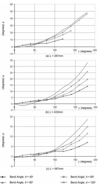
The photographs were taken with reference lines normal to the theoretical plane enablingφto be deter-mined. A full summary of the opposite and equal sense bend relationships betweenφandγ is shown in Figs 12 and 13. The data has been interpolated to improve the clarity of the figures.
Figure 12(a) displays the general trend betweenφ
[image:7.595.84.269.590.736.2]and γ for a tape length of 267 mm and an increas-ing bend angleθ. It can be seen that the gradient of the lines increases as γ increases and that the final magnitude of rotation ofφis very dependant on the bend angle of the fold (i.e. the data tends to fan out asγ increases). However, this separation of the data only noticeably begins at a twist angle of 60◦. At lower twist angles the bend angle has no clear effect on the relationship betweenφandγ. These trends generally remain constant as the length of the tape increases. However, the twist angle at which the data separates and fans out increases from 60◦to 80◦ and 100◦ for tape lengths of 433 and 567 mm, respectively. It can be concluded that as the tape length increases, the mag-nitude of the principal curvature rotation (φ) reduces
Fig. 11 Sample photographs of principal curvature for opposite sense bends,θ=80◦,L=267 mm
for a constant twist angle (γ). However, it can also be seen that up to a certain magnitude of twist the bend angle has no effect on the rotation of the principal curvature lines. This limiting magnitude increases as the tape length increases. Therefore, this data suggests that there is a complex interaction betweenL,θand
γ, and their combined effect onφ.
Figure 13(a) displays the equal sense bend relation-ship betweenφandγfor a tape length of 267 mm and varying bend angleθ. It can be seen that, as for the opposite sense bend case, the bend angle affects the relationship betweenφandγbut in the reverse way. An increase in the bend angle reduces the effect of twist onφ. The influence on the bend angle also starts fromγ =0◦, indicating that there is no angle of twist where the bend angle does not influence the rotation ofφ. This is a trend which is therefore only found to occur for opposite sense bends.
It could almost be concluded from Fig. 13(a) that the relationship betweenφandγ is linear. However, the data becomes highly non-linear as the tape length increases. This is most noticeable for the higher bend angle results where a drop inφcan be seen to occur. This is because of the principal curvature lines jump-ing to a position of minimum strain energy. It is known from the two-dimensional curvature analysis that for an opposite sense bend the point of maximum curva-ture occurs in the cross-sectional centre of the tape, whereas for an equal sense bend the maximum curva-ture occurs at the edges of the tape. This makes equal sense bends susceptible to edge imperfections result-ing in localized points of high curvature. However, the resultant effects of these localized points of high cur-vature are linked to the constraints imposed to the ends of the tape. In Figs 13(b) and (c), asγincreases,φ
jumps to new positions of minimum strain in relation to the edge imperfections of the tape at the fold loca-tion. From the data it can be seen that this only tends to occur once asγ rises to 180◦. This phenomenon was not found to occur at a bend angle of−40◦. This is because of the higher rigidity found in localized folds at low bend angles. The non-linearities observed in these experiments are beyond the scope of this research and have therefore not been investigated in any detail. However, they may well be important in determiningφfromγwhen a tape spring is mounted using various end constraints.
5.3 The relationship betweenλ1andφ
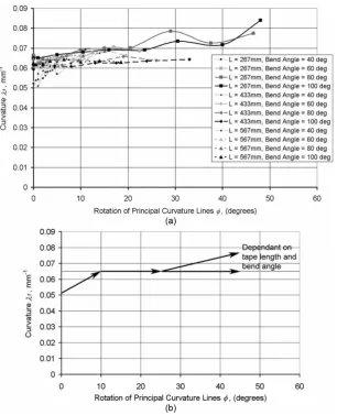
Fig. 14 Graph and trend of the opposite sense bend relationship betweenλ1andφ
equal sense bends. A full summary of the average curvature data for both bend directions is shown in
Figs 14(a) and 15. Again the data has been interpolated to improve the clarity of the figures.
[image:10.595.119.458.532.748.2]Fig. 16 Experimental hinge moment of postbuckling opposite sense bends overlaid with theoretical results
It can be seen from Fig. 14(a) that as the bend angle and twist (i.e. φ) increases, the curvature λ1 rises to the constant curvature assumption magni-tude of 0.065 mm−1. This is a similar trend to the two-dimensional case shown in Fig. 7. However, as the twist (henceφ) increases the curvature rises above the value of the constant curvature assumption. This rise is closely linked to the length of the tape spring as the applied twist rotations on shorter tapes pro-duces higher material strain at the fold point. For the medium and long tape lengths at high bend angles it can be seen that the curvature remains around 0.065 mm−1. The general trend of this data is displayed in Fig. 14(b).
For the three-dimensional deployment of tape springs, whereθandγ increase or decrease together, the curvature λ1 will rise at high angles (dependant on length) and fall at low angles. Therefore, a constant curvature assumption would generally result in hinge
moment over approximations at low bend angles and possible under approximations (dependant on length) at high bend angles. These are exactly the trends seen when the hinge moment is compared with experimental data from Walker and Aglietti [12] as shown in Fig. 16. In this caseM was determined using a constant curvature model whereas T was determined using a variable curvature model (based on empirical data). AsT dominates the high hinge bend angle moment and M dominates the low angle the inaccuracy due to the curvature assumption is seen at the low bend angle. Experimentally, the hinge moment increases at high bend angles because of the skew angle, which is ascribed to the increase inλ1and its affect onT. However, at high bend angles, there are only minor variations between the theoretical two-dimensional and three-two-dimensional approximations. (More details on the analytical approach are shown in Walker [10] and Walker and Aglietti [12].)
[image:11.595.104.516.573.750.2]The equivalent equal sense bend results show some similar trends and some reverse trends to those found in opposite sense bend case. From Fig. 15 it can be seen that as the bend angle increases the curvature decreases towards 0.065 mm−1. However, this is now much more dominant for all angles of twist. This is because of the averaging between the maximum and minimum curvatures where the maximum curvatures are dominated by the high curvature regions shown previously in Fig. 8. It can be seen from the data that the higher the bend angle the more likely the curva-ture is to rise (i.e. forL=433 mm atθ=100◦). This is also linked to the tape length, as the curvature rise is dramatic for short lengths but not applicable to long tape lengths. This data in Fig. 15 suggests that the cur-vature is potentially under approximated at both low and high bend angles for skew mounted tape folds.
However, from the hinge moment data shown in Fig. 17 it can be seen that magnitude of under approx-imation is within the possible variance of the tape thickness tolerance. This is because of the very low values of T produced by equal sense bend folds caused by its negligible effect on the material strain. Therefore, the dominate effect shown in the experi-mental data is the reduction of influence ofMabout the hinge line resulting in a reduction inMH[12].
6 CONCLUSIONS
This investigation has studied the curvature proper-ties of tape springs folded in both two- and three-dimensions and briefly compared this data to the hinge moment produced from the tape spring fold. From the previous studies of two-dimensional tape spring folds [7], it has been concluded that the length of the tape spring and the bend angle of the fold (after buckling has occurred) only has a minor effect on the opening moment of the tape. However, as soon as twist is added to the theoretical system, the length of the tape spring becomes critical. It directly influ-ences the rotation of the principle curvature lines, which has a varying impact on the curvature of the fold. To date, no analytical model exists that models the curvature at the fold as a function ofL, θ, and
γ. However, the comparison with the hinge moment data suggests that curvature variations are secondary to the possible variation caused by the tape thickness, resulting in the conclusion that constant curvature models are adequate for the tape lengths investigated in this analysis.
REFERENCES
1 Paine, M. D. and Gabriel, S. B. A micro-fabricated colloidal thruster array. In Proceedings of the 37th
AIAA/ASME/SAE/ASEE Joint Propulsion Conference and Exhibit, 2001, AIAA 2001-3329.
2 Fleeter, R.The logic of microspace, 2000 (Kluwer Aca-demic Publishers, Norwell, MA).
3 Watt, A. M.andPellegrino, S.Tape-spring rolling hinges. In Proceedings of the 36th Aerospace Mechanisms Symposium, Glen Research Center, 2002, pp. 1–14. 4 Givois, D., Sicre, J.,andMazoyer, T.A low cost hinge for
appendicies deployment: design, test and applications. In Proceedings of the 9th European Space Mechanisms and Tribology Symposium ESA/ESTEC, 2001 (available on CD-ROM).
5 Mansfield, E. H.Large-deflection torsion and flexure of initially curved strips.Proc. R. Soc. Lond. A, 1973,A 334, 279–298.
6 Seffen, K.,You, Z.,andPellegrino, S.Folding and deploy-ment of curved tape springs.Int. J. Mech. Sci., 2000,42, 2055–2073.
7 Seffen, K.andPellegrino, S.Deployment dynamics of tape springs.Proc. R. Soc. Lond., 1999,A 455, 1003–1048. 8 Calladine, C. R. The theory of thin shell structures 1888–1988.Proc. Instn Mech. Engrs, Part A: J. Power and Process Engineering, 1988,202(A3), 141–149.
9 ABAQUS User Manual, Getting started with ABAQUS/standard. Version 6.3, 2002 (Hibbitt, Karlsson & Sorensen, Inc., Pawtucket, RI).
10 Walker, S. J. I.A study of three dimensional tape spring folds for space applications. PhD Thesis, University of Southampton, 2004.
11 Grey, A. Modern differential geometry of curves and surfaces, 1993, pp. 270–271 (CRC Press, Boca Raton, FL). 12 Walker, S. J. I.andAglietti, G. S.Modeling the hinge moment of skew mounted tape spring folds.ASCE, J. Aerosp. Engng, 2007,20(2), 102–115.
APPENDIX
Notation
a width of undeformed tape spring
(mm)
E Young’s modulus of elasticity
(Nmm−2)
G shear modulus (Nmm−2)
L total tape spring length
M,M¯ bending moment applied to
the strip, and non-dimensional moment, respectively (about y-axis)
M∗ steady-state moment in the
theo-retical plane
Mmax peak moment in the theoretical
plane
M+∗,M−∗ steady-state moments for two-dimensional opposite and equal sense bends, respectively (N/mm) Mmax
MH moment about hinge line for a skew mounted tape spring (N/mm) Ry initial transverse radius of curvature
(alongy) (mm)
t tape spring thickness (mm)
T,T¯ twisting torque applied to tape (N/mm)
T+,T− opposite and equal sense bend torques, respectively (N/mm) x,y,z stationary coordinate system x,y,z moving coordinate system (fixed
rel-ative to the tape end)
α tape spring cross-sectional angle of embrace (rad)
γ relative twist angle between tape
ends
θ longitudinal bend angle of the
tape spring
κ surface curvature matrix
κx,0,κy,0,κxy,0 initial longitudinal, transverse, twisting curvatures, respectively
κx,κy,κxy final longitudinal, transverse, twisting curvatures, respectively
¯
κx,κ¯y,κ¯xy non-dimensional longitudinal, transverse, twisting curvatures, respectively
λ1,λ2 maximum and minimum
curva-tures along the lines of principle curvature
ν Poisson’s ratio
σyield material yield stress
φ rotation angle of principle