Iterative Channel Equalization, Channel Decoding and Source
Decoding
Jin Wang, Lie-Liang Yang, and Lajos Hanzo
School of ECS, University of Southampton, SO17 1BJ, UK Tel: +44-23-8059 3125, Fax: +44-23-8059 4508
Email: jw02r,lly,[email protected], http://www-mobile.ecs.soton.ac.uk
Abstract— The performance of soft source decoding is evaluated over dispersive AWGN channels. By employing source codes having error-correcting capabilities, such as Reversible Variable-Length Codes (RVLCs) and Variable-Length Error-Correcting (VLEC) codes, the soft-in/soft-out (SISO) source decoder benefits from exchanging information with the MAP equalizer, and effectively eliminates the inter-symbol interference (ISI) after a few iterations. It was also found that the soft source decoder is capable of significantly improving the attainable performance of the turbo receiver provided that channel equalization, channel decoding and source decoding are carried out jointly and iteratively. At , the performance of this three-component turbo receiver is about 2 dB better in comparison to the benchmark scheme carrying out channel equalization and channel decoding jointly, but source decoding separately. At this SER value, the performance of the proposed scheme is about 1 dB worse than that of the
-rate convolutional coded non-dispersive AWGN channel.
I. INTRODUCTION
Stimulated by the impressive performance gains of turbo codes and the turbo detection algorithms in general [1]–[3], iterative processing has been applied for tackling numerous communication problems [4]. In [5] an iterative source/channel decoding scheme was proposed for exploiting the redundancy imposed by a channel code and the residual redundancy in a Variable-Length Coded (VLC) source, where the VLC was viewed as a binary channel code. Similar schemes employing Variable-Length Error-Correcting (VLEC) codes and trellis coded modulation (TCM) were studied in [6] and [7], respectively, while a range of other turbo-detected schemes were investigated in [8]–[11].
Practical communication systems often suffer from inter-symbol interference (ISI) due to the dispersive nature of the channel. Douil-lardet al[12] proposed an iterative channel equalization and channel decoding technique – turbo equalization, designed for combating the ISI by considering the effect of the ISI channel as another form of error protection, i.e., as a rate-1 convolutional code.
In this paper, we propose an iterative channel equalization and source decoding scheme, where the redundancy in the source is ex-ploited for the sake of eliminating the channel-induced ISI. Transmis-sion schemes both with and without channel coding are considered. The rest of the paper is organized as follows. In Section II, we outline the communication system considered, including the source and the dispersive channel model. The Soft-In/Soft-Out (SISO) algorithms invoked by the equalizer and the source decoder are described in Section III, complemented by the corresponding simulation results. In Section IV, a coded transmission system communicating over the dispersive channel is investigated. Our conclusions are presented in Section V.
The financial support of the EPSRC, Swindon UK and the EU under the auspices of the PHOENIX as well as NEWCOM and NEXWAY projects is gratefully acknowledged.
Source
Non−binary
Source
Encoder
ISI channel Interleaver
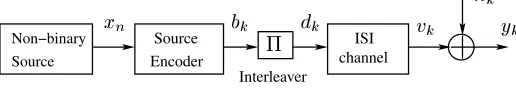
Fig. 1. Representation of a data transmission system including source coding and interleaver signaling through an ISI contaminated channel with additive white Gaussian noise.
II. SYSTEMOVERVIEW
A. Source Encoder
The non-binary source seen in Figure 1 represents a typ-ical source in a video, image, audio or text compression system. It is modelled as a discrete memoryless source associated with the finite alphabet , having symbol probabilities
of
, respectively. The output symbols of the source are forwarded to an entropy encoder, which outputs a binary sequence
, . The source code used in the entropy encoder may be a Huffman code, Reversible Variable-Length Code (RVLC) [13] or VLEC code [14]. Then, the resultant binary sequence is interleaved and transmitted over an ISI contaminated channel also imposing additive white Gaussian noise (AWGN), as shown in Fig. 1.
B. Channel Model
We assume having a coherent symbol-spaced receiver benefiting from the perfect knowledge of the signal phase and symbol timing, so that the transmit filter, the channel and the receiver filter can be modelled as a discrete-time linear filter having finite-length impulse response. Assuming binary phase shift keying (BPSK) modulation, the channel’s output , is given by
(1)
where the real-valued coefficients
are the channel impulse response (CIR) which are assumed to be time-invariant and known to the receiver, while
is the zero-mean AWGN having a variance of
. Furthermore, number of 0s are transmitted at the tail of a message, so that the discrete-time linear filter converges to the state of zero. Hence, a total of bits are transmitted per frame.
A tapped delay line model of the equivalent discrete-time chan-nel of Equation (1) is depicted in Figure 2. If we denote the state of the equivalent discrete-time channel at time by
, the channel’s output depends on the channel state
and on the input symbol
.
[image:1.612.313.571.204.248.2]¼ ½ ¾
[image:2.612.51.302.52.138.2]
Fig. 2. Tapped delay line circuit of the channel model Equation (1) for
,
,
,
.
k−1 k k+1
+1/−0.815
−1/−1.629 −1/−1.629
+1/−0.815
−1/0.815 −1/0.815
+1/0.815 +1/1.629
+1/0.815 +1/1.629
−1/−0.815 −1/−0.815
+1/−0.001 +1/−0.001
−1/0.001 −1/0.001
Fig. 3. Trellis diagram of the channel model seen in Figure 2. The states
are the possible
contents of the delay elements of Figure 2. The branches are labelled with the input/output pair .
Therefore, the equivalent discrete-time channel can be modelled as a Markov chain and its behavior can be represented by a trellis diagram (Fig. 3). A branch of the trellis is a four-tuple such that state at timecan be reached from state at time upon having the input
and output
,
where the output symbol at time
is the noise-free output of the channel model of Equation (1):
(2)
III. ITERATIVEEQUALIZATION ANDSOURCEDECODING
In this section we investigate the principles of iterative equalization and source decoding. We first describe the channel equalizer.
A. Equalization
The channel equalizer considered here is based on the MAP algorithm, which has been widely employed in turbo decoding [1], [2], [4], [15]. Following the approaches outlined in [4], [12], [16], the a posterioriLLR of the data bit
can be calculated as
Ý
Ý
(3)
where is the set of all index pairs corresponding to valid branches.
The term
can be computed via the backward recursion [16]:
¼
(4)
in conjunction with the initial value and for
. Similarly, the term
can be computed via the forward recursion [16]:
¼
(5)
associated with the initial value
and
for
. The term represents the transition probability from state
to state
, which can be expressed as
(6)
where
is the a prioriinformation of the transmitted data bit and is the channel pdf. At the channel, output given by Equation (1) we have
and taking into account the noise distribution we have:
(7)
As shown in Equation (6), once the channel output samples become available, the corresponding values of
can be computed and stored. With the aid of these values, bothof Equation (4) and
of Equation (5) can be computed, and finally, thea posteriori LLR of Equation (3) can be obtained.
B. SISO Source Decoding
In [17], Balakirsky first proposed a bit-level trellis representation for a VLC, which is similar to that of a convolutional code. Based on this trellis representation, the SISO MAP algorithm [18] used in the decoding of turbo codes [1] can be applied to the decoding of VLCs [5]–[7].
The trellis for a VLC is obtained by assigning the states of the trellis to the nodes of the VLC tree. The root node and all terminal nodes are assumed to represent the same state, since they all show the start of a new symbol. Other nodes, the so called internal nodes, are assigned one-by-one to the other states of the trellis. The number of states in the trellis is equal to the number of internal nodes of the tree plus one. As an example, Figure 4 shows the trellis corresponding to
the RVLC .
[image:2.612.82.268.181.330.2] [image:2.612.324.553.549.703.2]Decoder
SISO
[image:3.612.318.564.58.126.2]
Fig. 5. A SISO module.
We now derive the decoding procedure based on the SISO A Posteriori Probability (APP) module introduced in [19], which was a slightly modified version of the BCJR algorithm [18] and was originally designed for convolutional codes. The SISO module is a four-terminal device having two inputs and two outputs, as shown in Figure 5. It accepts as its inputs, and , namely the probability distributions of both the information symbols and code symbols labelling the edges of the code trellis, and forms the resultant outputs, and , which constitute an update of these distributions based upon the code constraints, and these outputs represent the extrinsic information.
Following the notation of [19], the extrinsic information is cal-culated as follows. At time the output probability distribution is evaluated as
(8)
whererepresents a branch of the trellis,,
, and
are, respectively, the output symbol, the starting state and the terminating state of the branch , while
is a normalizing factor that ensures maintaining
. The quantities and
are obtained through the forward and backward recursions [19], respectively, resulting in
(9)
(10)
in conjunction with initial values of
, and
for
all states, except for the root state, since the trellis always starts and ends at the root state.
In order to incorporate the source information, the branch transition probability in [19] is modified as follows:
(11)
where
is the source a priori infor-mation associated with the branch transition probability. It is time invariant and determined by the source distribution, which can be calculated with the aid of the state transition probabilities of [20], as,
(12)
where !are all the codeword indices associated with node in the code tree.
Therefore, the extrinsic information can be extracted by excluding the input probability of from the output probability, yielding
(13)
Deinterleaver
Equalizer
Interleaver
Channel Source
Decoder
Fig. 6. Receiver schematic performing iterative channel equalization and source decoding.
whereis, again, a normalization factor. Finally, the extrinsic LLR is given by:
(14)
C. Iterative equalization and decoding
The receiver structure performing iterative equalization and source decoding is shown in Fig.6. Given the channel output samples , the equalizer generates the a posteriori information
for the transmitted data bits according to the previously described recursive forward/backword detection algorithm. For the sake of avoiding that both detection stages rely on the same information in their decisions, which would preclude attaining iteration gains, the a prioriinformation
provided by the source decoder has to be excluded from
, before it is fed into the source decoder, yielding theextrinsicinformation .
Upon receiving the soft information from the equalizer, the source decoder also generates the extrinsic information
gleaned from the source code’s encoding constraints and the source distribution. This process is iteratively activated for a number of times, until finally the source decoder computes the estimates for the source symbols , by invoking MAP-based sequence estimation over the same bit-level trellis.
D. Simulation Results
We selected a three-path and a five-path discrete channel model from [21], which are highly frequency selective, resulting in severe ISI. The discrete channels are represented by their CIR taps as
(15)
(16)
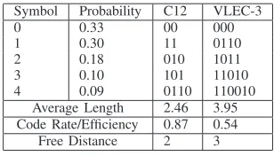
For the source encoder, we employed two different VLCs: an RVLC and a VLEC code, which are listed in Table I. The encoded data is permuted by a random bit interleaver of size bits.
TABLE I
VLCS USED IN THE SIMULATIONS
Symbol Probability C12 VLEC-3 0 0.33 00 000 1 0.30 11 0110 2 0.18 010 1011 3 0.10 101 11010 4 0.09 0110 110010
Average Length 2.46 3.95 Code Rate/Efficiency 0.87 0.54
Free Distance 2 3
[image:3.612.360.514.598.686.2]0 2 4 6 8 10 12 14 Eb/N0(dB)
10-6 10-5 10-4 10-3 10-2 10-1 100
SER
0 2 4 6 8 10 12 14
Eb/N0(dB) 10-6
10-5 10-4 10-3 10-2 10-1 100
SER
iteration #4 iteration #3 iteration #2 iteration #1 iteration #0
[image:4.612.60.256.78.233.2]AWGN Channel 5-Path Channel 3-Path Channel
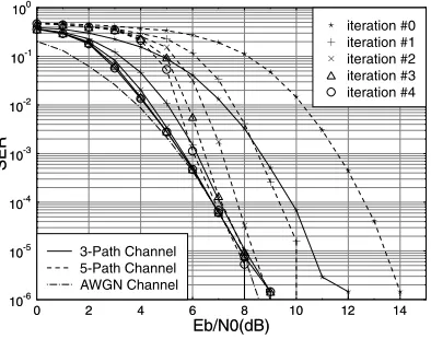
Fig. 7. SER performance of the RVLC for transmitting over the dispersive AWGN channels of Equation (15) and (16).
0 2 4 6 8 10 12 14
Eb/N0(dB) 10-6
10-5 10-4 10-3 10-2 10-1 100
SER
0 2 4 6 8 10 12 14
Eb/N0(dB) 10-6
10-5 10-4 10-3 10-2 10-1 100
SER
iteration #4 iteration #3 iteration #2 iteration #1 iteration #0
AWGN Channel 5-Path Channel 3-Path Channel
Fig. 8. SER performance of the VLEC code for transmitting over the dispersive AWGN channels of Equation (15) and (16).
channel
and over the 5-path ISI channel
of Equations (15) and (16). The performance of the same system over an AWGN channel is also depicted as a best-case performance “bound”. As shown in the figures, the iterative equalization and source decoding procedure converges, as the number of iterations increases. This behavior similar to that of a turbo equalizer [12], and effectively reduces the ISI after
iterations.
The performance of the system using a VLEC code is depicted in Figure 8 when transmitting over the 3-path ISI channel and over the 5-path ISI channel of Equation (15) and (16). Since the VLEC code has a larger free distance and hence a stronger error correction capability, the iterative channel equalization and source decoding procedure almost entirely eliminates the effect of ISI and approaches the non-dispersive AWGN performance bound after iterations.
IV. JOINTCHANNELEQUALIZATION, CHANNELDECODING AND SOURCEDECODING
In this section we assume that the source encoded data is protected by a channel code before its transmission over an ISI-contaminated channel, as shown in Figure 9. At the receiver the channel equaliza-tion, channel decoding and source decoding are iteratively performed. Generally, the joint iterative channel equalization and channel de-coding process is referred to as turbo equalization. However, when using SISO source decoding, the joint channel equalization, channel decoding and source decoding scheme of Figure 10 is additionally capable of exploiting the residual redundancy inherent in the source because we argued before that the VLC source encoder/decoder pair may be viewed as a channel codec.
Source
Encoder
Channel Encoder
channel ISI
[image:4.612.327.551.211.325.2]
Fig. 9. Transmitter diagram.
More explicitly, the corresponding receiver consists of three SISO modules, the channel equalizer, the channel decoder and the source decoder, as shown in Figure 10. All of them employ similar recursive forward/backward detection algorithms and generate soft output for the next processing stage. The channel equalization and channel decoding form the inner iteration. After a certain number of inner iterations, the source decoder is invoked and the extrinsic information is fed back for the next inner iteration. During our experiments, we found that the scheduling of one outer iteration after two inner itera-tions offered a good trade-off between complexity and performance. At the last outer iteration the source decoder generates the estimate
of the source symbol sequence by employing the classic Viterbi algorithm to the same bit-level trellis.
A. Simulation Results
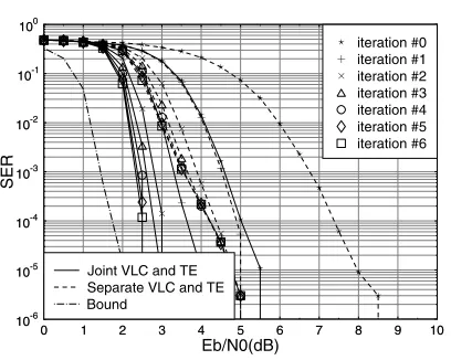
The attainable performance of the amalgamated turbo receiver depicted in Figure 10 has been evaluated when communicating over the 3-path ISI channel of Equation (15). The channel code used here is a half-rate, constraint length 5, recursive systematic convolutional (RSC) code, using the octally-represented generator polynomial" . The source code used is the RVLC C12 listed in Table I. The two interleavers are random bit interleavers having a memory of 2048 bits and 4096 bits, respectively.
The simulation results are depicted in Figure 11. The performances of both the joint and separate source decoding and turbo equalization are depicted. No outer iteration was executed in the separate source decoding based scheme. The performance of the same system over the non-dispersive AWGN channel after iterations is also depicted as a best-case performance ”bound”. As we can see in Figure 11, the joint turbo-detection scheme outperforms the separate source decoding based scheme by about 2 dB at SER= after iterations.
V. CONCLUSIONS
[image:4.612.60.257.327.482.2]Source Decoder Channel
Decoder
Inner Iteration
Equalizer
Outter Iteration
¼
[image:5.612.118.495.52.138.2]
Fig. 10. Receiver schematic.
0 1 2 3 4 5 6 7 8 9 10
10-6 10-5 10-4 10-3 10-2 10-1 100
0 1 2 3 4 5 6 7 8 9 10
Eb/N0(dB) 10-6
10-5 10-4 10-3 10-2 10-1 100
SER
iteration #6 iteration #5 iteration #4 iteration #3 iteration #2 iteration #1 iteration #0
Bound
Separate VLC and TE Joint VLC and TE
Fig. 11. SER performance of joint RVLC decoding, channel decoding and channel equalization over the three-path dispersive AWGN channel of Equation (15)
channels of Equation (15) and (16). An amalgamated iterative turbo equalization and SISO source decoding scheme was proposed for the sake of combating the ISI. The simulation results obtained demonstrate that even without the protection of channel codes, the redundancy in the source and source code can be exploited for effectively eliminating the ISI. In the context of channel coded transmission, soft source decoding has the potential of significantly improving the attainable system performance, provided that the channel equalization, channel decoding and source decoding are carried out jointly and iteratively. The design of concatenated systems based on semi-analytical tools, such as EXIT charts [23], constitutes our future research.
REFERENCES
[1] C. Berrou, A. Glavieux, and P. Thitimajshima, “Near shannon limit error-correcting coding and decoding: Turbo-codes,” inProceedings of
Inter-national conference on Communications (ICC), Geneva, Switzerland,
May 1993.
[2] J. Hagenauer, E. Offer, and L. Papke, “Iterative decoding of binary block and convolutional codes,” IEEE Transactions on Information Theory, vol. 42, pp. 429–445, Mar. 1996.
[3] S. Benedetto, D. Divsalar, G. Montorsi, and F. Pollara, “Serial concate-nation of interleaved codes: Performance analysis, design, and iterative decoding,”IEEE Transactions on Information Theory, vol. 44, no. 3, pp. 909–926, 5 1998.
[4] L. Hanzo, T. H. Liew, and B. L. Yeap,Turbo coding, turbo equalisation
and space-time coding for transmission over fading channels. John
Willy & IEEE Press, 2002.
[5] R. Bauer and J. Hagenauer, “On variable length codes for iterative source/channel decoding,” inProceedings of IEEE Data Compression
Conference(DCC), Snowbird, USA, April 2001, pp. 273–282.
[6] A. Hedayat and A. Nosratinia, “Concatenated crror-correcting entropy codes and channel codes,” inProceedings of International conference
on Communications (ICC), vol. 5, Anchorage, Alaska, USA, May 2003,
pp. 3090–3094.
[7] S. X. Ng, F. Guo, J. Wang, L.-L. Yang, and L. Hanzo, “Joint source-coding, channel-coding and modulation schemes for awgn and rayleigh fading channels,”Electronics Letters, vol. 39, no. 17, pp. 1259–1261, Aug. 2003.
[8] S.X.Ng, R.G.Maunder, J.Wang, L-L.Yang, and L.Hanzo, “Joint iterative-detection of reversible variable-length coded constant bit rate vector-quantized video and coded modulation,” in In Proceedings of the
European Signal Processing Conference (EUSIPCO), Vienna, Austria,
6-10 Sept. 2004.
[9] S.X.Ng, J.Y.Chung, F.Guo, and L.Hanzo, “Turbo-detection aided serially concatenated mpeg 4/tcm video transceiver,” inProceedings of IEEE
Vehicular Technology Conference (VTC), Los Angeles, USA, Sept. 2004.
[10] ——, “Turbo-detected unequal protection mpeg-4 wireless video tele-phony using trellis coded modulation and space-time trellis coding,” in
Proceedings of IEE International Conference on 3G Mobile
Communi-cation Technologies, Savoy Place, London, UK, 18 - 20 October 2004.
[11] ——, “Integrated wireless multimedia turbo-transceiver design - inter-preting shannon’s lessons in the turbo-era,” inIEE Sparse-Graph Codes
Seminar, Savoy Place, London, UK, 12th of Oct. 2004.
[12] C. Douillard, M. Jezequel, C. Berrou, A. Picart, P. Didier, and A. Glavieux, “Iterative correction of intersymbol interference: Turbo equalization,”European Transactions on Telecommunications, vol. 6, pp. 507–511, Sept.-Oct 1995.
[13] Y. Takishima, M. Wada, and H. Murakami, “Reversible variable length codes,”IEEE Transactions on Communications, vol. 43, no. 2/3/4, pp. 158–162, Feb./Mar./Apr. 1995.
[14] V. Buttigieg, “Variable-length error-correcting codes,”IEE Proceedings
of Communications, vol. 147, no. 4, pp. 211–215, Aug. 2000.
[15] S. Benedetto and G. Montorsi, “Unveiling turbo codes: some results on parallel concatenated coding schemes,”IEEE Transactions on
Informa-tion Theory, vol. 42, pp. 409–428, Mar. 1996.
[16] R. Koetter, A. Singer, and M. Tuchler, “Turbo equalization,”IEEE Signal
Processing Magazine, vol. 21, no. 1, pp. 67–80, Jan 2004.
[17] V. B. Balakirsky, “Joint source-channel coding with variable length codes,”Proceedings of IEEE Symposium on Information Theory, p. 419, July 1997.
[18] L. R. Bahl, J. Cocke, F. Jelinek, and J. Raviv, “Optimal decoding of linear codes for minimal symbol error rate,”IEEE Transactions on Information
Theory, vol. 20, pp. 284–287, Mar. 1974.
[19] S. Benedetto, D. Divsalar, G. Montorsi, and F. Pollara, “A soft-input soft-output app module for iterative decoding of concatenated codes,”
IEEE Communications Letters, vol. 1, no. 1, pp. 22–24, Jan. 1997.
[20] W. Xiang, S. Pietrobon, and S. Barbulescu, “Iterative decoding of jpeg coded images with channel coding,” inIEEE International Conference
on Telecommunications, Tahiti, France, Feb. 2003, pp. 1356–1360.
[21] J. Proakis,Digital Communications, 4th ed. New York: McGraw-Hill, 2001.
[22] T. Okuda, E. Tanaka, and T. Kasai, “A method for the correction of garbled words based on the levenshtein metric,”IEEE Transactions on
Computers, vol. C-25, no. 2, pp. 172–176, Feb. 1976.
[image:5.612.57.261.198.361.2]