University of Southampton Research Repository
ePrints Soton
Copyright © and Moral Rights for this thesis are retained by the author and/or other copyright owners. A copy can be downloaded for personal non-commercial
research or study, without prior permission or charge. This thesis cannot be
reproduced or quoted extensively from without first obtaining permission in writing from the copyright holder/s. The content must not be changed in any way or sold commercially in any format or medium without the formal permission of the
copyright holders.
When referring to this work, full bibliographic details including the author, title, awarding institution and date of the thesis must be given e.g.
AUTHOR (year of submission) "Full thesis title", University of Southampton, name of the University School or Department, PhD Thesis, pagination
Damage Stability of Ships as a Safety Criterion for Optimisation Tools
Thesis for the degree of Doctor of Philosophy
Deniz Saydan
UNIVERSITY OF SOUTHAMPTON
FACULTY OF ENGINEERING, SCIENCE & MATHEMATICS
School of Engineering Sciences
Damage Stability of Ships as a Safety Criterion for Optimisation Tools
by
Deniz Saydan
Thesis for the degree of Doctor of Philosophy
dedicated to
UNIVERSITY OF SOUTHAMPTON ABSTRACT
FACULTY OF ENGINEERING, SCIENCE & MATHEMATICS SCHOOL OF ENGINEERING SCIENCES
Doctor of Philosophy
DAMAGE STABILITY OF SHIPS AS A SAFETY CRITERION FOR OPTIMISATION TOOLS
by Deniz Saydan
A literature overview of past optimisation studies revealed that whilst satisfaction of intact stability requirements has been built into existing alternative hull form optimisation packages, seeking improved hydrodynamic hull forms in terms of seakeeping, calm water resistance and added resistance, damage stability is not an automated feature. Within the context of the hydrodynamic hull form optimisation techniques their application to novel hull forms would only permit use of deterministic damage stability analysis and as this is not straight-forward damage is applied after the hull is optimised. The damage must be relevant to ship type and applied in appropriate locations with sensible extents of damage. To fulfil this need both the Marine Accident Investigation Branch (MAIB) damage data base and a damage data base generated by Lutzen (2002) are interrogated and findings are reported.
I
CONTENTS
ACKNOWLEDGEMENTS ... XIII
NOMENCLATURE ... XIV
1. INTRODUCTION ... 1
1.1 The Ship Design Concept ... 1
1.2 Optimisation Tools ... 4
1.3 A Possible Shortcoming of Existing Optimisation Tools... 4
1.4 Aims and Outline of the Research... 5
2. THE OPTIMISATION PROCESS... 8
2.1 Background... 9
2.1.1 A Specific Motion and Resistance Driven Optimisation Research Programme ... 9
2.1.2 Ship Design Optimisation with Different Design Drivers ... 14
2.2 Discussion on Past Optimisation Studies ... 20
2.3 Statement of the Optimisation Process... 21
2.4 Summary... 22
3. ANALYSIS OF DAMAGE DATA... 23
3.1 Damage Statistics ... 23
3.1.1 Summary of Damage Statistics ... 59
4. THE DEVELOPMENT OF SHIP REGULATIONS AND STABILITY ANALYSIS ... 61
4.1 Development of Safety ... 61
4.2 The Deterministic and Probabilistic Approaches to Ship Stability Analysis . 66 4.2.1 The Deterministic Approach to Ship Stability Analysis ... 67
II
Added Weight Method... 70
4.2.2 The Probabilistic Approach to Ship Stability Analysis ... 70
4.2.3 Discussion on Current Stability Methods... 75
4.3 Damage Stability Suite ... 76
4.3.1 Independent Damage Stability Analysis... 77
4.3.2 Presentation of the Damaged Hull Forms ... 79
4.4 Summary... 80
5. SEAKEEPING ... 82
5.1 General Review ... 82
5.2 Frequency and Time Domain Approach ... 88
5.3 Justification of Selected Approach ... 89
5.4 Motion Analysis ... 90
5.4.1 Forces and Moments Acting on a Floating Ship in Waves ... 90
Forces and Moments Acting on an Intact Ship... 90
Forces and Moments Acting on a Damaged Ship... 91
5.4.2 The Equations of Motion... 91
Equations of Motion for Intact Hull Forms... 92
Equations of Motion for Damaged Hull Forms... 97
5.4.3 A Novel Method for Determining the Products of Inertia for Intact and Damaged Ship ... 101
The Intact Ship... 101
The Damaged Ship... 109
5.4.4 Determination of Motion Characteristics ... 112
5.4.5 Discussion... 113
6. SELECTION AND FUNDAMENTAL ANALYSIS OF BASIS SHIP ... 115
6.1 Choice of Hull Form... 115
6.2 Public Domain Particulars for Derbyshire... 116
6.3 Optimisation Objective Function and Design Parameters... 120
III
6.4 IMO Intact Stability Requirements and Related Analysis ... 125
6.5 Floodable Length Curve and Bulkhead Locations ... 129
6.6 Damage Properties of the Derbyshire... 132
6.7 The Damage Analysis... 134
6.8 Orientation of Damaged Hull Forms ... 134
6.9 Summary... 140
7. HYDRODYNAMIC CHARACTERISTICS OF INTACT AND DAMAGED SHIPS... 141
7.1 Calculation of Hydrodynamic Coefficients and Excitation Forces ... 142
7.2 Validation of Hydrodynamic Analysis of Intact and Damaged Forms of Derbyshire ... 145
7.3 Discussion of Hydrodynamic Data for Intact and Damaged Ships ... 155
7.4 Summary... 174
8. RELATIVE VERTICAL MOTION ANALYSIS OF INTACT AND DAMAGED SHIPS ... 175
8.1 Motion Dependent Qualities of Engineering Interest... 175
8.2 Selection of Points Investigated for Relative Vertical Displacement... 176
8.3 Comparison of Relative Vertical Motion for the Selected Points ... 180
8.4 Summary... 193
9. CONCLUSIONS AND FUTURE WORK... 194
9.1 Key Observation of Completed Research ... 195
9.2 Novel Aspects of Completed Research ... 199
9.3 Recommendations for Future Work ... 201
BIBLIOGRAPHY... 203
APPENDIX A – HOOKE – JEEVES ALGORITHM... 222
IV
APPENDIX C - NUMERICAL APPLICATION OF THE NEW METHOD TO DETERMINE THE MASS MOMENT OF INERTIA FOR PARENT
DERBYSHIRE AND FOR A TANKER HULL FORM ... 229
APPENDIX D - GENERAL ARRANGEMENT DRAWING OF THE
DERBYSHIRE... 233
APPENDIX E – GENERAL APPRAISAL OF DAMAGE SCENARIOS FOR PARENT DERBYSHIRE ... 235
APPENDIX F - ITERATIVE METHOD FOR DETERMINATION OF
EQUILIBRIUM TRIM AND HEEL ANGLES... 237
APPENDIX G – SENSITIVITY ANALYSIS OF THE PURE AND PRODUCT MOMENT OF INERTIAS TO THE EQUILIBRIUM ANGLES ... 239
APPENDIX H – HYDRODYNAMIC COEFFICIENT PLOTS FOR THE INTACT DERBYSHIRE AND FOR THE DAMAGED DERBYSHIRE
(SCENARIO A) ... 241
APPENDIX I – THEORY BEHIND THE RELATIVE VERTICAL MOTION . 248
APPENDIX J – RELATIVE VERTICAL MOTION FOR DIFFERENT
SELECTED POINTS ALONG THE SHIP ... 252
V
LIST OF TABLES
Table 3.1: Damage dimensions ... 59
Table 6.1: Main particulars of the Derbyshire taken from the Department of Transport (1989) ... 116
Table 6.2: The four masses and their longitudinal positions for parent Derbyshire ... 119
Table 6.3: The horizontal and vertical positions of the four masses for parent Derbyshire ... 119
Table 6.4: Parameters for the parent and optimised hull forms ... 124
Table 6.5: Intact stability curve areas calculated using Optistanbul suite ... 127
Table 6.6: Intact stability curve areas calculated using Wolfson unit hydrostatics and stability code ... 127
Table 6.7: Calculated IMO intact stability curve properties from Optistanbul suite ... 128
Table 6.8: Calculated IMO intact stability curve properties from Wolfson unit hydrostatics and stability code ... 128
Table 6.9: The four masses and their longitudinal positions for optimised Derbyshire ... 130
Table 6.10: The horizontal and vertical positions of the four masses for optimised Derbyshire ... 131
Table 6.11: Damage scenarios ... 133
Table 6.12: Parallel sinkage, trim and heel angles for damage Scenario A ... 135
Table 6.13: Parallel sinkage, trim and heel angles for damage Scenario B ... 135
Table 6.14: Parallel sinkage, trim and heel angles for damage Scenario C ... 135
Table 6.15: Parallel sinkage, trim and heel angles for damage Scenario D ... 135
VI
Table 6.17: Position of the centre of gravity for different damage scenarios for the optimised Derbyshire ... 137 Table 6.18: Position of the point masses for damage scenario A for the parent
Derbyshire ... 137 Table 6.19: Position of the point masses for damage scenario B for the parent
Derbyshire ... 138 Table 6.20: Position of the point masses for damage scenario C for the parent
Derbyshire ... 138 Table 6.21: Position of the point masses for damage scenario D for the parent
Derbyshire ... 138 Table 6.22: Position of the point masses for damage scenario A for the optimised
Derbyshire ... 138 Table 6.23: Position of the point masses for damage scenario B for the optimised
Derbyshire ... 139 Table 6.24: Position of the point masses for damage scenario C for the optimised
Derbyshire ... 139 Table 6.25: Position of the point masses for damage scenario D for the optimised
Derbyshire ... 139 Table 7.1: Hydrostatic coefficients for the intact case for the parent Derbyshire ... 171 Table 7.2: Hydrostatic coefficients for the damage case scenario A for the parent
Derbyshire ... 172 Table 7.3: Hydrostatic coefficients for the damage case scenario B for the parent
Derbyshire ... 172 Table 7.4: Hydrostatic coefficients for the damage case scenario C for the parent
Derbyshire ... 172 Table 7.5: Hydrostatic coefficients for the damage case scenario D for the parent
Derbyshire ... 172 Table 7.6: Hydrostatic coefficients for the intact case for the optimised
VII
Table 7.7: Hydrostatic coefficients for the damage case scenario A for the optimised Derbyshire ... 173 Table 7.8: Hydrostatic coefficients for the damage case scenario B for the optimised
Derbyshire ... 173 Table 7.9: Hydrostatic coefficients for the damage case scenario C for the optimised
Derbyshire ... 173 Table 7.10: Hydrostatic coefficients for the damage case scenario D for the optimised
Derbyshire ... 174 Table 8.1: Location of the points of interest on intact hull forms ... 179 Table 8.2: Location of the points of interest for the damaged parent Derbyshire hull
form ... 179 Table 8.3: Location of the equivalent points of interest for the damaged optimised
VIII
LIST OF FIGURES
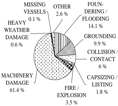
Figure 3.1: Relative occurrence of different classifications of accidents for UK
registered merchant vessels ... 25
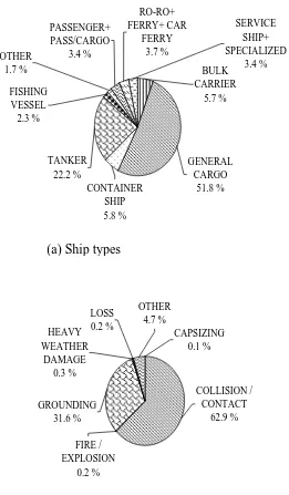
Figure 3.2: Relative occurrence of different classifications of accidents for UK registered fishing boats ... 27
Figure 3.3: Damage database (Lutzen (2002)) ... 29
Figure 3.4: Two main accidents from damage database (Lutzen (2002)) ... 31
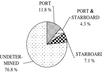
Figure 3.5: The representation of the location of the damage ... 32
Figure 3.6: Location of damage in collision incidents for different ship types ... 34
Figure 3.7: Location of damage in grounding incidents for different ship types ... 36
Figure 3.8: Damage properties in collision incidents for general cargo ships for the 3L/4-FP region ... 40
Figure 3.9: Damage properties in collision incidents for tankers for the 3L/4-FP region ... 43
Figure 3.10: Damage properties in collision incidents for containerships for the L/4-amidships region ... 46
Figure 3.11: Damage properties in collision incidents for containerships for the 3L/4-FP region ... 49
Figure 3.12: Damage properties in grounding incidents for general cargo ships for the amidships-3L/4 region ... 52
Figure 3.13: Damage properties in grounding incidents for tankers for the 3L/4-FP region ... 55
Figure 3.14: Damage properties in grounding incidents for bulk carriers for the 3L/4-FP region ... 58
Figure 4.1: The influence of permeability on the floodable length curve for a cargo/passenger vessel of 134m in length ... 69
Figure 4.2: Definition of the water head, ‘h’ (IMO (2002a)) ... 74
IX
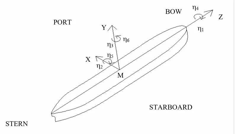
Figure 5.1: The motion-hydrodynamic Cartesian coordinate reference system ... 93
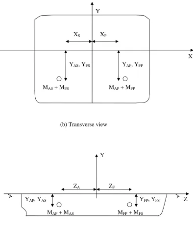
Figure 5.2: Total mass of the ship represented as four equivalent point masses ... 103
Figure 5.3: Description of the trim angle and parallel sinkage ... 110
Figure 5.4: Description of the heel angle ... 110
Figure 6.1: The parent hull form ... 117
Figure 6.2: The modified longitudinal mass distribution of the Derbyshire ... 118
Figure 6.3: The variation of the objective function and the calm water resistance with iteration number ... 122
Figure 6.4: The parent (continuous) and optimised (dashed) hull forms ... 123
Figure 6.5: Relative bow motion responses for the parent and optimised Derbyshire from Optistanbul Suite ... 124
Figure 6.6: The intact stability curves for the parent and for its optimised configuration ... 127
Figure 6.7: The presentation of the four point masses for the parent and optimised hull forms ... 130
Figure 6.8: The floodable length curves for the parent and optimised hull forms for different levels of permeability ... 132
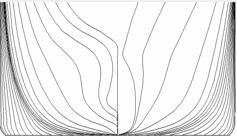
Figure 7.1: Discretisation of the intact Derbyshire ... 146
Figure 7.2: Discretisation of the intact optimised Derbyshire ... 147
Figure 7.3: Conditioning number for the intact Derbyshire ... 148
Figure 7.4: Sway-roll and roll-sway added mass and fluid damping coefficients for the intact Derbyshire ... 149
Figure 7.5: Surge wave excitation forces for the intact Derbyshire (in head seas) .... 150
Figure 7.6: Heave wave excitation forces for the intact Derbyshire (in head seas) ... 150
Figure 7.7: Pitch wave excitation moments for the Intact Derbyshire (in head seas) 151 Figure 7.8: Discretisation of the damaged Derbyshire scenario A. ... 152 Figure 7.9: Conditioning number for the damaged Derbyshire (scenario A) ... 152
X
Figure 7.11: Surge wave excitation forces for the damaged Derbyshire scenario A (in head seas) ... 154 Figure 7.12: Heave wave excitation forces for the damaged Derbyshire scenario A (in
head seas) ... 154 Figure 7.13: Pitch wave excitation moments for the damaged Derbyshire scenario A (in
head seas) ... 155 Figure 7.14: Pure surge added mass coefficient for intact and damaged hull
forms ... 156 Figure 7.15: Pure sway added mass coefficient for intact and damaged hull
forms ... 157 Figure 7.16: Pure heave added mass coefficient for intact and damaged hull
forms ... 157 Figure 7.17: Pure roll added mass coefficient for intact and damaged hull forms ... 158 Figure 7.18: Pure pitch added mass coefficient for intact and damaged hull
forms ... 158 Figure 7.19: Pure yaw added mass coefficient for intact and damaged hull forms ... 159 Figure 7.20: Pure surge fluid damping coefficient for intact and damaged hull
forms ... 159 Figure 7.21: Pure sway fluid damping coefficient for intact and damaged hull
forms ... 160 Figure 7.22: Pure heave fluid damping coefficient for intact and damaged hull
forms ... 160 Figure 7.23: Pure roll fluid damping coefficient for intact and damaged hull
forms ... 161 Figure 7.24: Pure pitch fluid damping coefficient for intact and damaged hull
forms ... 161 Figure 7.25: Pure yaw fluid damping coefficient for intact and damaged hull
forms ... 162 Figure 7.26: Heave induced surge added mass for the intact and damaged hull
XI
Figure 7.27: Pitch induced surge added mass for the intact and damaged hull forms ... 164 Figure 7.28: Roll induced sway added mass for the intact and damaged hull
forms ... 165 Figure 7.29: Yaw induced sway added mass for the intact and damaged hull
forms ... 165 Figure 7.30: Pitch induced heave added mass for the intact and damaged hull
forms ... 166 Figure 7.31: Yaw induced roll added mass for the intact and damaged hull
forms ... 166 Figure 7.32: Heave induced surge fluid damping for the intact and damaged hull
forms ... 167 Figure 7.33: Pitch induced surge fluid damping for the intact and damaged hull
forms ... 167 Figure 7.34: Roll induced sway fluid damping for the intact and damaged hull
forms ... 168 Figure 7.35: Yaw induced sway fluid damping for the intact and damaged hull
forms ... 168 Figure 7.36: Pitch induced heave fluid damping for the intact and damaged hull
forms ... 169 Figure 7.37: Yaw induced roll fluid damping for the intact and damaged hull
forms ... 169 Figure 8.1: Relative positions of the points of interest for the parent Derbyshire for
investigating vertical displacement ... 176 Figure 8.2: Heave motion for the intact and damaged parent and optimised hull forms of Derbyshire ... 181 Figure 8.3: Roll motion for the intact and damaged parent and optimised hull forms of
Derbyshire ... 181 Figure 8.4: Pitch motion for the intact and damaged parent and optimised hull forms of
XII
Figure 8.5: Relative vertical motion responses for the intact and damaged hull forms for point A (in head seas) ... 183 Figure 8.6: Relative vertical motion responses for the intact and damaged hull forms for
point B (in head seas) ... 184 Figure 8.7: Relative vertical motion responses for the intact and damaged hull forms for
point G (in head seas) ... 184 Figure 8.8: Relative vertical motion responses for the intact and damaged hull forms for
point C (in head seas) ... 187 Figure 8.9: Relative vertical motion responses for the intact and damaged hull forms for
point F (in head seas) ... 187 Figure 8.10: Relative vertical motion responses for the intact and damaged hull forms
for point D (in head seas) ... 188 Figure 8.11: Relative vertical motion responses for the intact and damaged hull forms
XIII
ACKNOWLEDGEMENTS
I would like to thank to all of the following people without whom this research could not have been undertaken.
In particular, I would like to thank to Dr. Ö. Belik, Professor P. Temarel and Professor P.A. Wilson, without their presence such a research could not have started. It was a great pleasure to work under the supervision of Professor G.E. Hearn. I am really grateful for his support and encouragement. In addition his and Jenny Hearn’s excellent hospitability is greatly appreciated. My thanks are also directed to the members of the Department of Ship Science, staff and students.
The opportunity to meet Dr. Lützen arose at just the right time. I greatly appreciate the discussions with her during this research.
I would like to acknowledge Özgür for his invaluable help, support and encouragement.
NOMENCLATURE
At the end of variable definitions a list of acronyms used within the text are defined.
a Distribution density of damage location along ship’s
length
wpc
a Waterplane area of compartment, that is, area between selected
bulkheads
A Attained survival probability index
[ ]
A Linear motions coefficient matrix including hydrodynamic,hydrostatic and mass distribution influences
kj
A
⎡ ⎤
⎣ ⎦
Added mass matrix for intact ship. Elements Akj denote addedmass coefficient for hydrodynamic reaction in kth direction arising from motion in the jth direction. The pure added mass coefficient for j, k = 1,2,3 is given in kg, whereas the pure added mass coefficient for j, k = 4,5,6 is presented in kg m2. Finally, the cross-coupled added mass coefficients are given in kg m
kj
A′ ⎡ ⎤
⎣ ⎦ Added mass matrix of damaged ship. A′kj is value of Akj for
damaged ship
max
A Required subdivision index associated with probabilistic
approach to damaged stability of a ship
wps
A Waterplane area of intact ship
wps
A′ Waterplane area of damaged ship
AP, FP Aft and forward perpendiculars of ship
AP, Subscripts indicating quantity associated with aft portion of ship
either to port or starboard AS
b Either penetration of damage (m) or base points for the objective
B Breadth (or moulded beam) of ship
kj
B ⎡ ⎤
⎣ ⎦ Fluid damping matrix of intact ship. Bkj denotes fluid damping
coefficient for hydrodynamic reaction in kth direction arising from motion in the jth direction. The pure fluid damping coefficient for j, k = 1,2,3 is given in kg rad/s, whereas the pure fluid damping coefficient for j, k = 4,5,6 is presented in kg m2 rad/s. Finally, the cross-coupled fluid damping coefficients are given in kg m rad/s
kj
B′ ⎡ ⎤
⎣ ⎦ Fluid damping matrix of damaged ship. B′kj is value of Bkj for
damaged ship
WL
B Breadth of ship at still waterline
B
C Block coefficient
kj
C
⎡⎣ ⎤⎦ Hydrostatic restoring matrix of intact ship. is hydrostatic coefficient for restoration in k
kj
C th
direction arising from motion in
the jth direction. The pure hydrostatic coefficient for j, k = 3 is
given in kg/s2, whereas the pure hydrostatic coefficient for j, k = 4,5 is presented in kg m2/s2. Finally, the cross-coupled
hydrostatic coefficients are given in kg m/s2
kj
C′ ⎡ ⎤
⎣ ⎦ Hydrostatic restoring matrix of damaged ship. is value of
for damaged ship
kj
C′
kj
C
N
C Conditioning number of hydrodynamic fluid structure
interaction influence matrix of ship being analysed
P
C Prismatic coefficient
WP
C Waterplane area coefficient
dm Elemental constituent mass for ship
dm′ Elemental constituent mass of ingressed water
D Depth of intact ship
F Factor of subdivision, assumed distribution function of damage location along ship’s length and wave exciting forces and
moments matrix.
k
F Time dependent wave exciting force/moment in kth direction
for intact ship. Fk used to form kth row of F. The wave exciting force for j, k = 1,2,3 is given in kg m/s2, whereas the wave exciting moment for j, k = 4,5,6 is presented in kg m2/s2
k
F′ Corresponding value of Fk for damaged ship
FP, Subscripts indicating quantity associated with forward portion of
ship either to port or starboard FS
g Acceleration due to gravity
( )
g x Objective function in Hooke-Jeeves optimisation method
GM Metacentric height
GZ Righting lever
max
GZ Maximum righting lever
h Either elevation of water on deck, measured with respect to
undisturbed free surface or height of damage (m) presented as a proportion of the ship depth D
( )
H ω Motion transfer function
S
H Catamaran demi-hull separation parameter
HJ Step length in Hooke-Jeeves optimisation method
i, j, k subscripts used singly or in pairs to denote a member of a group of values.
XX
I ,IYY,IZZ
or Pure moments of inertia of intact ship
55
I ,I66,I44
XX
I′ ,IYY′ ,IZZ′
or Pure moments of inertia of damaged ship
55
I′ ,I66′ ,I44′
XY
I ,IZX,IYZ
or Products of inertia for intact ship
56
I ,I54,I46
XY
I′ ,IZX′ ,IYZ′
or Products of inertia for damaged ship
56
I′ ,I54′ ,I46′
max
J Maximum non-dimensional damage length
XX
k ,kYY ,kZZ Radius of gyration with respect to X, Y and Z axis respectively
l Extent of damage (m)
, p r
l l Levers for pitch and roll motions
L Length of ship between perpendiculars
OA
L Overall length of ship
S
L Moulded length of ship
WL
L Length of vessel at still water waterline
LCB Longitudinal centre of buoyancy
LCF Longitudinal centre of flotation
LCG Longitudinal centre of gravity
w
m Total mass of ingressed water
M Ship mass
AP
M ,MAS,MFP,MFS Representative point masses for intact ship
AP
M′ ,MAS′ ,MFP′ ,MFS′ Representative point masses for damaged ship made up from intact ship point masses and ingressed water
kj
M ⎡ ⎤
⎣ ⎦ Generalised mass matrix of intact vessel
kj
M′ ⎡ ⎤
⎣ ⎦ Generalised mass matrix of damaged vessel
l
M Mass of liquid contained within a compartment of the intact ship
XYZ
M Earth-fixed right-handed Cartesian frame of axes (X, Y, Z) with
its origin, M, located at the intersection of the undistributed free-surface, the mid-ship section and the longitudinal central plane of symmetry of the ship in its intact position of static equilibrium.
n Iteration number
i
p Probability of damage of either the ith ship compartment or ith
group of ship compartments
R Required subdivision index, often used in stability regulations as
being an equivalent alternative designation for Amax
( )
R ω Response spectrum
( )
,RVM z x Amplitude of vertical relative displacement
i
s Probability of survival of either the ith ship compartment or ith
group of ship compartments
( )
S ω Wave spectrum
( )
,V
S z x Amplitude of vertical displacement
W
S Wetted surface of ship
t Time
T Draught of ship
V Service speed of ship
lost
w Structural mass loss due to ship damage
x Variables for the objective function in Hooke-Jeeves
optimisation method
1
x , x2 Distance from the aft terminal of to the foremost/ aftermost
portion of the aft/forward end of the compartment being considered
S
L
P
X ,XS Transverse distance of port and starboard specified point
masses with respect to MXYZ
AP
Y ,YAS, , Vertical distance of aft and forward located port and starboard
point masses
FP
Y YFS
B
Y Vertical centre of buoyancy for intact ship
B
Y′ Vertical centre of buoyancy for damaged ship
SINK
Y Measure of extent of parallel sinkage
z Vertical position of damage (m)
Z,X ,Y Distance of elemental ship mass coordinates with respect to the
MXYZ reference system
Z,X ,Y1 New location of X , Y, Z after ship experiences parallel
sinkage
A
Z ,ZF Longitudinal distance of aft and forward located point masses
A
Z′,XP′, YAP′ Location of MAP for the damaged ship
A
Z′′,XS′, YAS′ Location of MAS for the damaged ship
C
Z ,XC,YC Centre of flotation for intact ship
C
Z′,XC′,YC′ Centre of flotation for damaged ship
F
Z′ ,XP′′, YFP′ Location of MFP for the damaged ship
F
Z′′,XS′′, YFS′ Location of MFS for the damaged ship
G
Z ,XG,YG Centre of gravity for intact ship
G
Z′ ,XG′ ,YG′ Centre of gravity for damaged ship
m
Z ,Xm,Ym Location of elemental constituent mass for intact ship
m
Z′ ,Xm′ ,Ym′ Location of elemental constituent mass for damaged ship
w
Z ,Xw,Yw Location of elemental mass of water
1
Z ,X ,Y2 New location of X , Y , Z after ship heels
1
Z ,X1,Y3 New location of X , Y , Z after ship trims
α Angle to determine the position of bulkheads
∆ Displaced weight for intact ship
′
∆ Displaced weight for damaged ship
(
z x t, ,)
ζ Complex wave amplitude
η Six degree of freedom motion displacement column matrix
j
η Time dependent motion response of intact ship in jth degree of
freedom. The motion response amplitude for j=1,2,3 is given in metres, whereas the motion response amplitude for j=4,5,6 is
presented in radians.
j
η′ Time dependent motion response of damaged ship in jth degree
of freedom
j
η Velocity in jth degree of freedom for intact ship
j
η′ Velocity in jth degree of freedom for damaged ship
j
η Acceleration in jth degree of freedom for intact ship
j
η′ Acceleration in jth degree of freedom for damaged ship
ja
η Complex amplitude of jth degree of freedom motion response of
intact ship
ja
η′ Complex amplitude of jth degree of freedom motion response of
damaged ship
ji
η , ηjr Imaginary and real parts of ηja
ji
η′ , η′jr Imaginary and real parts of η′ja
k
η Generalised direction cosine in the kth direction
θ Heel angle
c
µ Volumetric permeability of the damaged compartment
2
µ Surface permeability of the damaged compartment
c
v Compartment volume
i
v Intact volume of ith compartment or ith grouping of
compartments
jn
v Normal velocity component of point on wetted surface of ship
due to oscillation in the jth degree of freedom
lost
v Lost buoyancy volume
ρ Associated material density
l
ρ Fluid density
s
ρ Sea water density
φ Either trim angle or time independent velocity potential
D
φ Diffraction velocity potential
j
φ Radiation velocity potential associated with motion in jth degree
of freedom
ji
φ , φjr Imaginary and real parts of j
th
radiation velocity potential
W
φ Velocity potential of incident wave
Φ Time dependent velocity potential defined
ω Wave frequency
∇ Displaced volume for intact ship
′
∇ Displaced volume for damaged ship
CEM Concept exploration model
CFD Computational fluid dynamics
HARDER Harmonization of rules and design rationale
IMCO Inter-governmental maritime consultative organisation
IMO International maritime organisation
ITTC International towing tank conference
MAIB Marine accident investigation branch
MARPOL The international convention for the prevention of pollution
from ships
. .
O B O Oil-bulk-ore
RAO Response amplitude operator
RBM Relative bow motion
RO-RO Roll on roll off
SEM Static equivalent method
SOLAS Safety of life at sea
UK United Kingdom
1
1. INTRODUCTION
This dissertation addresses the impact of damage upon the hydrodynamic and hydrostatic characteristics and the motion responses of a ship hull form optimised for seakeeping with no increase in calm water resistance. To appreciate how optimisation may assist the ship design process, a short overview of ship design approaches is provided in the next section. This is followed by a brief overview of what optimisation can achieve and this provides the identification of a possible shortcoming in existing optimisation tools for improved hydrodynamic performance. It is this possible defect and its consequences that drive the research.
1.1 The Ship Design Concept
Ship design is an interesting and demanding task. It provides the best opportunity of combining theoretical analysis, scientific knowledge of hydrostatics, hydrodynamics, dynamics, materials and structures, with the historical experience that include ‘perceived’ beneficial ratios of geometric dimensions and form factors.
Depending on the ship type a ‘volumetric’ or ‘deadweight’ design will be undertaken to identify the principal hull form characteristics for the required cargo capacity, ship speed and range. Volumetric design is used when the ship must provide a specific amount of cargo space. This approach is applied to passenger ships, containerships and most naval ships. Deadweight design is based on equating the sum of the lightship component masses and the cargo masses to the ship displacement. It is used mainly in the design of tankers and bulk carriers.
2
The preliminary design stage is generally carried out in three ways. The first method is known as the basis ship approach. This technique, which uses a particular existing hull form to lead the families of designs. This approach was very useful when the number of new ships being constructed was high, so that design can be optimised by small improvements from ship to ship and class to class. However, when the number of new ships constructed decreases, such as at the present time and single vessel classes become more common this method looses its effectiveness.
Another design method is to use the ‘trend curves’. This method is based on the plots of the data gathered from existing ships (see, for example, Watson (1962) and Watson & Gilfillan (1977)). This technique provides an interval of values for specific ship sizing parameters to be used. Consequently, the quality of new designs based on this approach depends on both the relevance and inappropriateness of previous designs included in the associated database. This aspect of design is also discussed by Sarioz (1993). Furthermore, this method limits the capability of the designer to create novel designs, as the new designs based on this method will have similar features.
The third option is the ‘parametric survey’ (see, for example, Murphy et al. (1965) and Gilfillan (1969)). This approach looks for the most advantageous combination of overall ship dimensions and form parameters within defined limits of the design study. This method tries to find the optimum hull form for the prescribed criteria but it does not look at different alternatives.
3
The indicated technical analyses are usually carried out when the design geometric characteristics are well established. Therefore, some required changes may not be accommodated due to the level of commitment to the design and the perceived costs in design re-development. The failure to reflect the results of the most accurate analysis in the design process limits the usefulness of empiricism and experience based design methods. An alternative approach is to apply rational computer-based searches or optimisation tools in the earlier design stages to improve the measures of merit for seakeeping, resistance, structural and economic qualities.
The complexity of the design relies on different features of the technical design, the construction of the ship and its operation. As the ship dimensions have a direct effect on material and construction cost the ship-builder requires a design with minimum dimensions to achieve the prerequisites of the ship owner. At the same time the operator of the ship restricts the design for the minimum operational and capital costs.
Because of these different objectives and its multidisciplinary nature the ship design process is developed iteratively. This iterative process can be expressed schematically as a design spiral (see, for example, Andrews (1981)). At the design spiral early estimates of the ship sizing parameters are made. As the design proceeds along the spiral these estimates are altered and developed as different levels of analysis of differing complexity are applied. This continuous evolution of the design is the result of the feedback provided at subsequent steps and increased information about the sensitivities of the design. The process continues until convergence and a final economic and technical feasible design is produced.
4
The internal subdivision of the ship by means of transverse and/or longitudinal watertight bulkheads or by horizontal subdivisions like double bottoms in commercial ships might add to the cost of the ship. This unavoidably involves a compromise between safety and cost. The more severe the standard adopted for subdivision and stability, the greater the probability that capital and operating costs will increase and the economic viability of the ship may be compromised. Therefore, the stability requirements are usually satisfied at the minimum level required by the Classification Authorities.
1.2 Optimisation
Tools
A design based optimisation tool generally determines a technically more advantageous set of design parameters. The parameters may be related through specific mathematical functions or defined by some empirical formulae. These parameters will be subject to physical, technical, legal and economic restrictions. If more than one combination of the design variables satisfies all these conditions, the algorithm within the optimisation tools determines that combination of design variables that optimises the hull form for some measure of merit specified by the designer (see, for example, Schneekluth & Bertram (1998)). This ability to iterate several hull form parameter changes at the design stage encourages the designer to carry out alternative modifications of the design parameters in a way that was not previously possible.
1.3 A Possible Shortcoming of Existing Optimisation Tools
5
et al. (1991)). However, it is not evident that damage stability is addressed at all in such optimisation tools. Therefore, it could be the case that the computer based optimisation programs, which are used for improving the behaviour of the ‘non-damaged’ hull form in terms of seakeeping, resistance, structural strength and economy may lead to ship designs that are less survivable when damaged. Essentially this is the question addressed in this research programme (see Saydan and Hearn (2004)).
1.4 Aims and Outline of the Research
The absence of damage stability considerations in an optimisation routine that addresses hydrodynamic performance subject to intact stability may be viewed as incomplete. To determine whether this is the case one must either include damage stability in the optimisation process and examine its impact on the computer programme outcomes, or, undertake hydrodynamic and motion analyses of an assumed non-optimised hull form and its optimised hull form to try and demonstrate a shortcoming in the optimisation process. At this stage there is no need to comment on the pros and cons of either possible approach since it is necessary to investigate all aspects of the posed problem and to identify a possible feasible way forward. Certainly it would be extremely perverse if one were to find that a damaged optimised hull form was less survivable than the associated damaged conceptual form.
Improving hydrodynamic performance requires appropriate modification of the geometric form of the basis hull. Modifying the hull form is not an easy task without an appropriate wealth of design/operational experience related to the ship type addressed. Hence a systematic process to try and identify the beneficial changes is required. This could be undertaken by using design charts, that is, plots of ship behaviour characteristics as a function of different design pairings. These pairings are designated primary or secondary parameter changes (‘L and B/T’ form the first set and CWP, LCB
6
Having perceived which changes are beneficial in terms of the vessel designed, the continuous iteration of the selected parameters should be undertaken by using a suitable algorithm in order to produce new hull forms. This could be achieved using so called ‘inverse analysis’ whereby hull form shapes have preferable seakeeping and resistance responses (compared to the initial designed ship) are sought by seeking out beneficial geometric changes. In Chapter 2 this inverse analysis is explained and the approach of different researchers is reviewed. Various researchers have used different objective functions (or drivers). The Hooke-Jeeves optimisation process (see, for example, Hooke & Jeeves (1961), Kowalik & Osborne (1968), Aoki (1971) and Walsh (1975)) is used to provide an optimised hull form.
Prior to attributing damage to any ship (optimised or otherwise) it is necessary to understand what damage is most likely together with most likely location and the expected extent of the damage. These aspects are discussed and appropriate statistical results presented in Chapter 3.
Chapter 4 reviews the development of ship regulations and stability analysis and identifies why certain developments have taken place over the past 76 years. Two possible methods of examining the stability of a ship when it is damaged are discussed. The first one is deterministic and is mandatory, whereas the second one is probabilistic approach and is used when the deterministic method is found unsatisfactory. An intense analysis of the two different stability methods provides their advantages and disadvantages for the intended damage research. Selection of the deterministic approach is justified in the care of general optimisation used with novel hull forms.
7
The hydrodynamic analysis of the optimised hull and basis hull for the intact and damage cases is carried out using the Matthew Diffraction Suite (Hearn (1978)). In Chapter 6 the Hooke-Jeeves optimisation process as built into the Optistanbul Suite (Sarioz (1993)) is applied to the selected Derbyshire hull form. The reasons for its selection and the objective function and constraints used are explained. Validation of the intact stability of both basis and optimised hull forms are provided together with approval of the bulkhead division in each case. The damage statistics of Chapter 3 are used to determine the orientation of the parent and optimised Derbyshire hull form for four distinct damage scenarios.
Chapter 7 then undertakes a three-dimensional hydrodynamic analysis of all selected ten hull forms and justifies the quality of the results prior to undertaken relative vertical motion response calculations in Chapter 8.
8
2.
THE OPTIMISATION PROCESS
The improvement of ship design using optimisation techniques requires selection of an appropriate optimisation tool, the selection of an objective function that reflects the improvements sought and appropriate supporting analysis to undertake evaluation of the parameters (variables) included in the selected objective function. The process is essentially iterative with the initial independent parameters (variables) being gradually modified so as to generate improvements in the selected metric or metrics of interest. Optimisation can be misleading if one aspect of the design is improved with little or no consideration of other equally important aspects. The quality of the outcomes can also depend upon the ability of the analysis tools to properly reflect the impact of changes in the governing design parameters selected. The governing parameters selected, if inappropriate may limit the capability of the optimisation process to identify a true global optimal solution.
Thus optimisation tools may provide a large number of alternative designs within a relatively short time with better characteristics than the parent design. In many cases important constraints will have influenced the outcome. In this chapter previously applied optimisation tools, applied in the context of improved hydrodynamic and motion characteristics, will be reviewed and assessed in terms of their strengths and weaknesses and their potential to include damage stability assessments.
9
2.1 Background
2.1.1 A Specific Motion and Resistance Driven Optimisation Research Programme
In the late 1980s, Hearn et al. (1988) developed a Frank close-fit (see Frank (1967)) velocity potential based strip theory for in-house seakeeping analysis within the design offices of British Shipbuilders. Since there was little familiarity (within the design offices) with the mathematical formulation and solution of either the ship motions & the dynamic shear force/bending moment characteristics or the associated fluid structure interaction analysis the computer system developed ‘Lynette Suite (Hearn et al. (1988))’ required many self correcting and automatic recovery processes. Because the designers in British Shipbuilders would not agree to geometric data being provided in a preferred form, automatic spline fitting through arbitrary defined waterplanes and transverse sections was necessary to generate required geometric data at the usual 21 stations. This in turn also required automatic discretisation of the stations to allow the necessary hydrodynamic analysis. Availability of robust friendly software with error detection and recovery was thought by the authors to be a necessary tool to allow improved initial designs within British Shipbuilders. It was soon evident that the designers could not control the development of the hull forms using fully automated analysis. A search methodology was required to indicate what level of changes was needed to achieve the desired performance improvements. Thus the need for seeking an optimisation process was industry based not research driven within the academic environment.
10
influential in affecting the design and the sensitivity of the different hydrodynamic characteristics to different level of changes in different hull form parameters. Having gained some insight through the ‘Forward technique’, a fully automated optimisation approach the ‘Inverse technique’ was developed since it used the analysis to identify the hull form design parameter values. Both techniques seek cause and effect information regarding the hydrodynamic characteristics dependence upon hull form parameters.
The forward technique simply analyses the required engineering responses for defined variations of the selected hull form parameters. The literature search undertaken by Hearn et al. (1990) indicated the dependence of ship motions upon the secondary parameters of CWP, LCB and LCF. Consequently, these secondary parameters were
investigated on the basis they influenced seakeeping and related quantities, but were not present in standard empirical resistance calculation formulae. Hence it was argued that seakeeping could be influenced without significantly influencing resistance characteristic. This information is used to generate so called ‘design charts’ that provide a three-dimensional graphical representation of the ‘cause and effect’ relationship for different engineering responses as a function of different pairs of hull form parameters. In theory one could use the resulting surface plots to try and identify beneficial changes of the ‘initial’ hull. Secondary parameters are investigated using the Lackenby transformation (see Lackenby (1950)) to change the sectional area curve (to change LCB) and the waterline curve (to change LCF and CWP). Each parameter can be
modified without influencing the other two parameters. A year later, Hearn et al. (1991) included the effect of altering the primary parameters of L and B/T. The primary parameters are modified by using linear distortion methods in which the displacement of the ship and its block coefficient remain fixed. Thus any proportional change in ship length is balanced by appropriate adjustments of the value of the product of beam and draught subject to B/T remaining invariant.
changes that provide improved engineering responses per se. In each step a hull form is generated and analysed. Initially, the Landweber-Macagno three parameter conformal mapping procedure (see Landweber & Macagno (1959)) was used to develop each modified transverse section. The hydrodynamic characteristics of these sections are then determined using a Frank close-fit method. A year later, the generation of alternative hull forms is produced using the Lackenby transformation by Hearn et al. (1991).
In the inverse approach the optimisation technique of Hooke-Jeeves (see Appendix A) was employed. The responses investigated were seakeeping responses selected from a menu of possibilities, the wave making resistance and the frictional resistance subject to the intact stability characteristics complying with the IMO requirements (outlined in Section 6.4 of this dissertation). The objective function was a linear combination of the selected hydrodynamic responses, each scaled with respect to the response of the parent (initial) design. Initially the objective function has a value of unity. The parameter changes allowed were specified as part of the input data on the basis it should be the designer who stipulates no-change or specifies permissible levels of change for each parameter. Similarly the selection of those responses that are considered more critical for the efficient operation of the ship operating on a specific route should be specified by the designer prior to applying either the ‘forward’ or ‘inverse’ analyses.
Ship responses in random waves are modelled by Hearn et al. (1990 and 1991) using the linear spectral analysis (see, for example, Lloyd (1998) and Saydan (1999)), that is, irregular waves are assumed to correspond to the superposition of regular waves having different wave lengths, wave amplitudes and directions. Having selected a wave spectrum, S
( )
ω , representation of the operational area of the sea and calculated the motion transfer functions, H( )
ω , of the ship (and its variants resulting from the optimisation search) the response spectrum or spectra can be calculated using( )
( ) ( )
2R ω = H ω S ω .
The term H
( )
ω 2 is often referred to as the response amplitude operator (RAO). Various statistical parameters of the response may be determined such as probability of slamming, acceleration thresholds being exceeded, deck wetnesses et cetera.The area under the response spectrum defines the variance of the ship responses to the selected sea-state. Firstly this area is minimised for all sea states. In practice, Hearn et al. (1992) and Sarioz et al. (1992) found it more suitable to reduce the peak value of the response amplitude operator of selected response(s). This approach required less computational effort and produced the same optimised hull form parameter values given by the initial computationally intensive approach. The reduction of peak values leads to a general reduction in the response amplitude operator amplitudes and the response motion spectrum values are automatically decreased for all sea-states.
Sarioz et al. (1992) found that application of other researchers’ optimisation techniques such as that of Lloyd (1991) based on optimising in a specific sea-state often meant the optimised form was better in the selected sea-state but not all sea-states. Hearn et al. (1990, 1991 and 1992) and Sarioz et al. (1992)’s approach does not exhibit this characteristic. Their optimisation method produced new hull forms which showed better hydrodynamic characteristics for all sea-states. In these mono-hull studies strip theory (see, for example, Salvesen et al. (1970)) is implemented for the seakeeping analysis; whereas a selection of resistance prediction techniques were included such as the method of Holtrop & Mennen (see Holtrop & Mennen (1982) and Holtrop (1984)) together with thin-ship wave-making resistance of Michell (1898) and International Towing Tank Conference (ITTC) 1957 frictional resistance correlation curve, see, for example, Hearn & Wright (1999). Intact stability is usually checked against the International Maritime Organisation’s criteria contained within IMO A-749 (see Section 6.4). Manoeuvring analysis was added to the forward technique by Furukawa & Hearn (2000). It is based on IMO manoeuvring requirements see, IMO (1993). Hearn et al. (2000) added manoeuvring analysis to the inverse part of the optimisation process.
13
The mono-hull studies by Hearn et al. (1990, 1991 and 1992) and Sarioz et al. (1992) were restricted to vertical motions in head waves such as heave, pitch, relative bow motion (RBM) and slamming. This was because the authors, like Lloyd (1991), believed that if a ship is optimised for vertical motions in head seas, it will generally show better characteristics in other motions. In the study of multi-hull vessels by Hearn et al. (1994, 1995a and 1995b) the same motion characteristics are analysed in head seas with the inclusion of roll in bow and quartering seas; whereas again only the vertical motions are analysed in head waves in Hearn et al. (1995c) and Hearn & Wright (1997, 1998a and 1998b).
For the twin-hull vessels the demi-hull separation parameter ‘HS’ is added to the
primary parameters because the graphs of hydrodynamic coefficients of the twin hulls plotted by Hearn et al. (1994) were significantly different for variations of this demi-hull separation parameter. The wave-making resistance is calculated in these twin-demi-hull studies using a modified Michell thin-ship theory (see Lunde (1951)) so that interaction between demi-hulls is included as necessary, this is dependent upon demi-hull separation and forward speed of advance (see, for example, Hearn & Wright (1997) and Tuck (1987)). The Michell thin-ship theory is chosen because it has the advantage of consistency of treatment regarding seakeeping and wave resistance in the sense that both analysis methods use actual hull form shape rather than global hull form parameters. In order to facilitate a wider range of hull parameter combinations, the secondary parameters were extended to include ‘CP’ in Hearn & Wright (1998a and
1999). CP does not directly influence the optimisation results, but facilitates seakeeping
and resistance conflict resolution through greater variation of the other parameters with practical ship forms maintained.
14
for efficient and accurate motion analysis without real-time calculation of required hydrodynamic coefficients using Frank close-fit in-line. However, once the database is provided the hydrodynamic coefficients for several alternative hull forms are generated within a small amount of time. Then as in mono-hull studies, linear distortion methods and the Landweber-Macagno three parameter conformal mapping procedure or Lackenby transformation techniques are used in order to generate new hull forms.
For mono-hulls, in order to minimise a selected response of the ship, standard optimisation techniques such as Hooke-Jeeves can be used. This is possible because the objective function associated with the selected response of the ship has only one minimum. However, the hydrodynamic coefficients of twin hulls plotted for heave motion by Hearn et al. (1994) for two different non-dimensional hull separation coefficients show the highly nonlinear variation of the catamaran responses with hull geometry variations. Thus, whilst linear analyses were used in the calculation it was found that the responses were very nonlinear with respect to the hull form design parameter changes and so the Hooke-Jeeves approach was not appropriate. So a new ‘evolutionary programming’ based search strategy was proposed by Hearn et al. (1995a and 1995b) to cope with the nonlinear nature of the catamaran objective function. This ‘Genetic Algorithm’ (see Hearn et al. (1995a and 1995b) and Bertram (2003)) made it possible to converge to the global minimum despite the design charts being full of local minima.
2.1.2 Ship Design Optimisation with Different Design Drivers
15
design process starts by the assumption of three ship lengths, then by using the plots and relations provided in Watson (1962) and Watson & Gilfillan (1977) it is possible to determine beam, draught and block coefficient and hence obtain a displacement. Once the lightship weight for each ship is calculated through the plots and relations of Watson (1962) and Watson & Gilfillan (1977), it is subtracted from the displacement to obtain deadweight values for three different ships. The three deadweight values plotted versus length gives the possibility to identify the required ship length for the deadweight specified at the beginning of the design. This procedure used historical data. Thus it is possible that new designs generated, using this data, may be influenced by both relevant and inappropriate previous designs. Another disadvantage of the method lies in the fact that the use of historical data limits the capability of the designer to create novel designs, as the new designs will have features similar to those of the database.
Over the period 1965-1985 several attempts were undertaken to solve the problem of identifying ship sizing parameters by computer algorithms. They were developed by Murphy et al. (1965), Mandel & Leopold (1966), Gilfillan (1969), Nowacki et al. (1970), Fisher (1972) and Lyon & Mistree (1985). There were two basic optimisation methods used in these cited papers.
16
and T) were expressed as functions of ship length. Then all calculations regarding the power, weight, stability and cost were carried out by the computer code for each trial length. Again the desired design was not available directly, but it was selected by examination of the output of the computer code.
However, in the second method mathematical programming is employed to achieve optimum solutions. The final result arrived at the computer algorithm is the desired result sought by the designer, whereas in the first approach the output from graphical manipulation or the computer code does not lead directly to an optimum. There is always some further refinement of the process. In the computer oriented optimisation techniques either direct or random search techniques (see, for example, Fisher (1972) and Mandel & Leopold (1966)) or nonlinear programming (see, for example, Nowacki et al. (1970) and Lyon & Mistree (1985)) are applied.
The preliminary ship design stage has frequently been viewed as an economic optimisation problem with the physical, technical and legal aspects treated as restrictions or constraints. Consequently, the design process becomes a multi-criteria optimisation problem as demonstrated by Sen (1992) and Ravn (2002). In the earlier cited papers, Murphy et al. (1965) used only the ship construction cost in their economic criteria; whereas Fisher et al. (1972) considers it better to render some approximation to all factors rather than disregard some of them entirely. Therefore Fisher et al. (1972) include impact of taxes, bank interest and borrowed capital to owner’s capital ratio. The optimisation problem is that of seeking minimum cost of each ton of cargo each year as a function of fleet size.
17
An investigation of the seakeeping performance of the British Ship Research Association merchant series is carried out by Wilson (1986). By his method it is possible to consider large number of different designs at early design stage at a small cost penalty which is only a function of the speed of the processor in the computer used. The need of a philosophy, which uses recent advances in computer graphics to understand the nature of the design process and to create radically new ship design synthesis, is extensively discussed in Andrews (1981, 1986 and 2003).
Different optimisation techniques (random and direct) are compared by Keane et al. (1991) for the minimum resistance of a frigate of 3300 tonnes displacement. Such an optimisation process requires generation of the mathematical hull forms see Keane (1988).
Doctors & Day (1995) introduced the genetic algorithm into their research to improve catamaran ferries in terms of wave resistance so as to reduce the erosions of river banks by wash. Later, their analysis was extended to include also vertical acceleration in head seas (Day & Doctors (1997)). The wave resistance is calculated by either Holtrop & Mennen in Keane et al. (1991) or Michell thin-ship theory in Doctors & Day (1995) and Day & Doctors (1997). The first method has the advantage of covering a wide range of ship types of varying sizes; whereas the thin-ship theory of Michell is more sensitive to the change of hull form parameters, since it uses the actual hull form shape rather than global hull form parameters to determine the wave resistance. The Michell thin-ship theory has also been used extensively by Tuck & Lazauskas (1998) for predicting the wave resistance for multi-hulls.
18
(1997) by investigating the influence of prismatic coefficient on catamaran resistance. Whilst all these works have been performed in calm water, Molland et al. (2001) examined the performance characteristics of catamarans in head and oblique waves. Finally, Ghani (2003) investigated the influence of bulbous bows on the high speed displacement catamaran performance in shallow water condition.
Keane & Robinson (1999) suggested that research in the conceptual design of ships should not focus only on dealing with different hull form ‘innovation’, but also should seek to find better search techniques in optimisation. Different optimisation techniques in the sense of Keane & Robinson (1999) are provided by Schneekluth & Bertram (1998) and Holden et al. (2002).
In automatic optimisation designer interaction is not needed (see, for example, Janson & Larsson (1996)). However, such an approach risks the optimum design not being practical. Therefore an interactive optimisation that does not leave the designer out of the design process, but supports him with his decision making is more preferred. However, the designer should be clear with respect to what his/her objectives are as the computer program cannot automatically perform the optimisation without a clear framework.
19
In the use of expert systems (see, for example, Dai et al. (1994) and Bertram (2003)) a knowledge database is built up from the knowledge of experts within a particular specialisation. In this technique the designer may specify the appropriate inputs but the outputs are purely a function of the inbuilt expertise, there is usually little scope for the designer to strongly influence the process outputs. This method has the disadvantage of producing similar ships to those of an experienced designer. The need for a full automatic or an interactive optimisation procedure is considered by Schneekluth & Bertram (1998), Liu et al. (1981) and Keane & Robinson (1999). It is suggested that an efficient optimisation technique coupled with the interaction of the ship designer is more suitable for the optimisation process. In the papers of Hearn et al. (1990, 1991 and 1992) it is also assumed that constraints on parameter variation and objective function context are the responsibility of the designer. That is, the final range of ship dimensions should be selected by a naval architect who understands the relationships between different design parameters and the information presented by optimisation tools. Therefore, an optimisation procedure should not absolve the designer of his responsibility, but assist him with his decisions.
20
variation of the design parameters systematically and this omits the evaluation of the effect of changes of design parameters on the hydrodynamic responses.
Pawlowski et al. (2004) proposed a way to use the floodable length curve as a function of s, conditional survival probability of a ship following the flooding of each compartment in turn. This method presents a novel approach for effective subdivision at the early stages of the design. However, their technique suffers from some numerical instability that presents different solutions for the same initial conditions and case.
2.2 Discussion on Past Optimisation Studies
The discussed optimisation tools could be considered incomplete, from a safety point of view, as they are only concerned about the intact stability of ships and they do not address damage stability. To assess the significance, or otherwise, of this omission it was decided to carry out the hydrodynamic analysis and hence dynamic motion responses of hull forms in the intact and damage case for the ship as ‘designed’ and ‘when optimised’, to try and understand the influence of damage upon optimised hull forms. In particular, the work carried out at the University of Newcastle has demonstrated that for different ship types (trawlers, containerships, warships and catamarans) it is possible to improve seakeeping, wave-making resistance and added resistance whilst satisfying the IMO intact stability conditions imposed. Since no apparent obvious disadvantage (in terms of the metrics used) exist with the intact ship it might be the case (however perverse) that the disadvantages show themselves when studying the damaged ship.
21
example, Keane et al. (1991). In the next section the optimisation method applied in this research programme will be described in greater detail.
2.3 Statement of the Optimisation Process
22
The Optistanbul Suite (see Sarioz (1993)) is used in this study in order to optimise the selected basis hull form (see Section 6.2). This software represents an extension of the method originally developed at the University of Newcastle upon Tyne. As before, a database of hydrodynamic coefficients (added mass and fluid damping) for a suitable representative set of transverse sections is used for the hydrodynamic analysis. The optimisation of a hull form is provided using the Hooke-Jeeves algorithm. The primary parameters within the optimisation process are modified by using linear distortion methods and the secondary parameters are varied by using Lackenby transformation to change the sectional area curve or the waterline curve. The generation of alternative hull forms is produced by linear distortion or, in the case of Sarioz (1993) by the Lackenby transformation. Having edited the software to provide some of the omitted main and print algorithms, optimisation of the basis hull form was undertaken for an objective function based on minimisation of the peak relative bow motion (RBM) in head seas subject to the constraint that calm water resistance is not increased. RBM is selected as an objective function since it includes the amplitude and phase information of both the heave and pitch motions, which in turn are coupled to surge for the intact ship and coupled to all other motions in the case of a damaged ship.
2.4 Summary
Having reviewed optimisation process in a specific hydrodynamic/motion context and also reviewed more general aspects of optimisation, it is noted that safety aspects rarely provide the driver of the process, but may occur in the context of a constraint. Therefore, a way ahead has been suggested that permits a suitable combination of two-dimensional hydrodynamic optimisation and three-two-dimensional post damage hydrodynamic analysis.
23
3.
ANALYSIS OF DAMAGE DATA
In this chapter the damage statistics are investigated in order to provide a general appreciation of those accidents that have led to capsize or to the loss of a ship. These damage statistics are prepared by the Marine Accident Investigation Branch (MAIB). When analysing the damage statistics, this organisation treats fishing boats and merchant vessels as two distinct industries. Hence, these two vessel types will be examined separately. In addition to the damage statistics prepared by MAIB, the ‘Lutzen 2002’ damage database is analysed to provide a general understanding of the damage location and the extent of the damage. These studies will influence the selection of the ship to be analysed and the location and extent of damage to be investigated on such a ship.
3.1 Damage
Statistics
The MAIB investigates marine accidents involving UK registered ships in world-wide waters and non-UK registered ships in UK territorial waters. The gathered information is published as a collection of short reports and accidents statistics only for the UK registered ships. The statistics extracted are presented here as pie-charts for merchant vessels in Figures 3.1(a), 3.1(b) & 3.1(c) and for fishing boats in Figures 3.2(a), 3.2(b) & 3.2(c) respectively.