Rochester Institute of Technology
RIT Scholar Works
Theses
Thesis/Dissertation Collections
5-19-2017
Assembly Language
Joe S. Lee
Follow this and additional works at:
https://scholarworks.rit.edu/theses
This Thesis is brought to you for free and open access by the Thesis/Dissertation Collections at RIT Scholar Works. It has been accepted for inclusion in Theses by an authorized administrator of RIT Scholar Works. For more information, please [email protected].
Recommended Citation
Assembly Language
byJoe S. Lee
A Thesis submitted to the Faculty of
Rochester Institute of Technology
College of Imaging Arts and Sciences
School of American Crafts
In Candidacy for the Degree of
MASTER OF FINE ARTS in Ceramics
Abstract:
“Assembly Language” is a culmination of an exploration, through the medium of ceramics, in understanding complexity that arises through the interactions between simple
components.
In the realm of computer science, the term “Assembly Language” refers to a low-level programming language for any programmable digital device. It is typically just one step above writing in the raw ones and zeros of binary. Every program at some point needs to be translated into assembly language so that it can be understood by the device, and every program that has ever been written for a digital device is essentially composed of a series of these simple
assembly language instructions.
In this body of work, I use the metaphor of the role of assembly language in computer science to explore a similar process of breaking down complex systems into simple components and then using those simple components to construct new complex systems.
The starting point for this investigation is the design of a root component that would have common physical interface points with other instances of that component. My choice of a root component is a five-degree tapered column with a height that is four times the length of one of the sides of its largest hexagonal end. I created a synthetic phylogeny of the components used in the creation of works for this show. A component’s ancestor within this phylogeny is the one with the most influence on the revisions to create the new component.
Thesis Committee Signatures:
Thesis Title: Assembly Language
Thesis Author: Joe S. Lee
Thesis Committee Final Approvals:
Chief Advisor: Jane Shellenbarger
Date:
Associate Advisor: Peter Pincus
Date:
Associate Advisor: David Schnuckel
Date:
Department Chairperson: Glen Hintz
Contents:
Abstract:
...
2
Thesis Committee Signatures:
...
3
Contents:
...
4
List of Works:
...
6
Introduction:
...
7
1 Foundations for Investigation:
...
7
1.1 Personal Context and Motivations...7
1.2 Foundational Concepts...8
1.3 Hypothesis and Methods...9
1.4 The Introduction of Fused Deposition Modeling (FDM) Technology...10
2.1 Design Details of Components...12
Images of Synthetic Phylogeny...13
2.2 Production Details of Components...14
2.3 Methodologies for the Interfacing of Components...14
3 Documentation of the Work:
...
15
Focal Pieces:...15
Colonies:...20
Spires:...26
Sequences:...30
Frameworks:...37
4 Analysis of Results:
...
41
4.1 Thoughts on the Implications of Using FDM Technology...41
4.2 Thoughts on the Analytical Methodology Used in the Making of Sculpture ...42
4.3 The Emergence of Four Categories of Organization...42
Frameworks:...42
Sequences:...43
Spires:...43
Colonies:...43
4.4 Thoughts on the Themes of Modularity...44
4.5 Relationship to Existing Work...45
3D Printing in Ceramics...45
The Nature of the Digital in Art...46
4.6 The Role of Aesthetic Evaluation in the Work...47
Conceptual Explorations on the Nature of the Individual...49
Technical Explorations...50
5 Technical Appendices
...
51
5.1 Clay Body and Glaze Formulations and Details...51
Cone 10 Translucent Porcelain for Printing...51
33COE Compatible Clay for Printing...51
Yixing Inspired Printing Clay...52
SG-4 Clear “Joining” glaze...52
5.2 Notes on Calibrating Auger Based 3D Printer Extruders...53
List of Works:
Atlas Spire
...
16
Hex Fractal
...
17
For my $n(1..4)
...
18
Diversity Colony
...
19
Colony 001
...
21
Hex Coupler Core Colony
...
22
Radial Hex Shell Colony
...
23
Elevated Colony
...
24
4 Hex Composite Colony
...
25
4 Hex Radial Centralized Spire
...
27
4 Hex Radial Offset Spire 60 Degree Rotation
...
28
4 Hex Radial Offset Spire 120 Degree Rotation
...
29
3 Hex Cell Stack
...
31
4 Hex Cell Spiral (Black)
...
32
4 Hex Cell Stack
...
33
4 Hex Cell Spiral (Buff)
...
34
4 Hex Honeycomb Cell Stack
...
35
4 Hex Cell Spiral (White)
...
36
Chirality
...
38
4 Hex Radial Framework
...
39
Introduction:
My work is rooted in the spirit of discovery through experimentation. Having been educated as an engineer and having worked for over a decade in the semiconductor industry, my instincts have been honed to strive for understanding of the root causes and effects behind the workings of systems. In transitioning into studying ceramics, I have redirected these instincts to use the format of sculptural ceramics in exploring the nature of interconnectedness in the world.
The sculptures that I create present themselves as compelling visual structures that draw the viewer in for closer examination. There are opportunities, upon closer examination, for the viewer to observe for themselves that the whole of the sculpture is composed of individual components. These components are each unique characters in their own right. However, when systematically and methodically organized, they form a whole that is greater, in both tangible properties like size and intangible properties like complexity and conceptual depth, than what could be achieved individually. Although this organization may appear similar to design, the methodology used in this body of work extends beyond the limitations of design techniques when dealing with issues of complexity.
In my explorations of the modular format, I am framing my work as a metaphor for social interactions between individuals who come together to form societies and civilizations. I am especially interested in the themes of what individuality can contribute when working within a much larger group with distinctly diverse members. By creating symbolic vignettes of the interactions between elements of diversity and conformity, my work invites viewers to be more mindful in their considerations to the complex interactions found in life.
1 Foundations for Investigation:
1.1 Personal Context and Motivations
The most influential theme in my creative work is the challenge in understanding the difficult to predict ways that interactions influence the functions and states of individual components within complex systems. In my case, I have an existential requirement in being able to accomplish this task quickly and effectively. Being the child of first generation Chinese immigrants to the United States, I had very little guidance in navigating western society. Throughout my entire life, I have had to be able to quickly evaluate a social situation with its intricacies in values, traditions, customs, and biases in order to act in a way that was deemed appropriate by the majority of people around me on a daily basis. My visible differences in physical appearance afforded me little room for error. When I inevitably failed at this task, the response of those around me would vary from a light teasing to physical violence, but there is always some kind of response. To this day, this remains a constant exercise. Because of this, my skills at quickly breaking down and isolating the essential elements in order to formulate an effective solution or response has become acutely honed. The methodology I found to be most effective in tackling this is the scientific method where a hypothesis is formulated using the best information available at the time and then tested trough application. The information gathered from the test, regardless of whether it was successful or not, is then used to refine the
hypothesis to start the process again.
solutions to the potential number of problems that may occur has become an ever-vigilant instinct even when there are no problems to solve or data to analyze. When I was working as an engineer, any spare processing instinct was filled by the technical challenges of my job. Now, I have chosen to direct this set of skills towards my creative practice. I cannot stop this drive to understand the world and to synthesize that knowledge into something to construct my
internalized model of understanding. Everything that I researched and learned has helped in my mental understanding of the universe, which in turn has helped to improve my ability to navigate the intrinsically biased society I have to contend with on a daily basis. The consequences of failure at this task are still very real, especially given the current political climate in the western world.
In redirecting my focus to the more creative field of ceramics, I have taken on a new form of this challenge of systems analysis. Once again, I find myself as on outsider, this time because of my training and background, and I must work to properly interact with those who are rooted in a different background and perspective. However, my goals this time are not just to be accepted, but to become a bridge between fields that can greatly benefit from increased
interaction and collaboration. From straddling the worlds of the scientific and the creative, I can see numerous opportunities for furthering both fields through communication and cooperation.
I have found myself drawn to especially difficult problems and complex systems because my experience has been that they provide the most rigorous tests of my abilities and offer the best chances for me to improve them. Among the most complex systems I have encountered are social dynamics and the influence of creative works upon them. In approaching this task I’ve attempted to break down seemingly overwhelming complexity into smaller components and then to distill those components down into essential qualities. “Assembly Language” is a culmination of my exploration of these systems through the medium of ceramics. It is also a demonstration of the possibilities within the intersection of modern science and contemporary craft. This body of sculptural work was approached from the perspective of a scientific exploration, but my goal was not for it to be just a body of sculptural work or just a scientific exploration. Instead, my intention is for “Assembly Language” to be a combination of the two that becomes more than what a scientific exploration, or an exhibition of sculptural work, can be on its own.
1.2 Foundational Concepts
As a guide for this, I have drawn upon a number of areas under current scientific and mathematical research around complexity as case studies for approaching my own explorations through the medium of ceramics. These areas include fractal geometry, procedural generation, emergent behaviors, and chaos theory.
My interest in fractal geometry started when I first discovered the field as a teenager. Although I had encountered fractal geometry through its ties to the field of chaos theory, my initial interest was rooted in the graphs that resulted from chaotic processes rather than those processes themselves. I was drawn to the infinite complexity of these graphs, which were often quite visually beautiful. Finding out that they were also mathematically elegant only increased their beauty for me. I was fascinated with the paradox that these images were both extremely simple in their foundations, but unfathomably complex in their final manifestations. I was also excited by these geometries because if infinite complexity could arise from something that could be expressed so simply, there might be a possibility that immensely complex things may be reduced to something simple enough for a person to understand.
engineer. My job was to test and debug server class microprocessor designs. The exponentially increasing complexity of their design made testing them to be a seemingly impossible task, since it quickly became physically impossible to write and execute any set of tests that would ensure absolute correctness. Instead of relying on writing individual tests, the field depended on writing programs that would generate tests with the hope that an algorithm, if pointed in the right direction, would generate tests that would expose a weakness or a flaw so that it could
subsequently be fixed before the design went into production. This technique opened up a number of paths in my thinking because it offered a way to mitigate dealing with an
overwhelming number of interconnected relationships by designing tools that would generate inputs that would explore those interconnected components in ways that would be difficult for a human to design, and thus offered a way to tackle the difficulties of complexity with my own controlled complexity.
I had observed emergent properties long before I knew there was a field of study around them. Like many others, I marveled at the sight of bird flocks, fish schools, and insect swarms where each group appeared to have a higher level of organization dictating the group’s motions. The field of study around emergent behaviors examines how these complex higher level actions are the result of the interactions between the simpler acts of individual agents that make up that group. This field became an essential inspiration in showing me that complexity can arise out of interactions of multiple simple components which interact and organize across different scales.
Finally, although I did not directly study chaos theory deeply until after encountering my other topics, its tendrils are intertwined with all of the mentioned areas. For example, the graphs of many chaotic processes turn out to be fractals, procedural generation techniques can be better understood and more effectively designed when considering “the butterfly effect1,” and emergent properties are especially spectacular when examining chaotic systems. The concepts of chaos theory are at the core of my investigations into complex systems, since at its core, chaos theory was essentially conceived by mathematicians for the express purpose of analyzing and understanding complexity.
1.3 Hypothesis and Methods
In synthesizing this research, my formulated hypothesis was to examine whether visually compelling complex three dimensional objects could be achieved through interactions of
relatively simple three-dimensional components. To test this hypothesis, the experiment would be to distill down a handful of particularly adaptable physical interfaces, such as matching surfaces, angles, and positive and negative spaces, and to incorporate them into simple modular component “building blocks.” I would then attempt to create visually compelling sculpture through only using multiples of these simple modular objects.
The starting point for this investigation is the design of a root component that would have common physical interface points where other instances of that component could attach. My choice of a root component is a five-degree tapered column with a height that is four times the length of one of the sides of its largest hexagonal end. As I explored the possible interactions between multiples of this base component, I noted how some interactions worked well, such as when the combination of multiple components created an angle or a negative space that provided an opportunity where other components or combinations of components could attach, while others were forced or not possible. These learnings were used to create subsequent
A concept invented by the American meteorologist Edward N. Lorenz to highlight the the effect 1
components that would be available for use in future pieces. This iterative design cycle was repeated when enough data became available from experimentation to formulate a new component design.
1.4 The Introduction of Fused Deposition Modeling (FDM) Technology
Early on in this process, I relied on making plaster molds for slip casting off of a plastic FDM 3D printed positive of the designed components. This process provided a way to quickly produce a significant number of components, but the front-end cost of creating these plaster molds limited the amount of variation that could be introduced into the component designs.
Relying heavily on the information published by Bryan Czibesz on his work on
constructing an extruded ceramic 3D printer I built a 3D printer specifically to help me create this body of work2. My motivations to explore adapting FDM 3D printing techniques to use extruded ceramic paste were that it would allow for a more direct realization of my digitally designed components. Building my own ceramics 3D printer allowed me to quickly explore variations in the design of components without having to invest time and effort in making a complex mold system in order to have physical components to test. In the time it takes to print my root
component, the print time (~30 minutes) was comparable to the time it takes for me to slip cast one component using a plaster mold (~15 minutes for slip to set, and ~15 minutes until I can remove the component from the mold). For this investigation, the benefits of rapid design turn-around time in being able to have physical components of potential new components to test outweighed the benefits of the ability to rapidly produce large numbers of parts.
Additionally, my experimentation with incremental improvements of extruded ceramic 3D printing opened up a number of capabilities in using the technology that would be difficult to achieve using other existing ceramic techniques. These capabilities influenced the choices made in designing the next generation of components to use in the works. They also allowed for improvements and innovations in producing instances of all existing designs.
The first advantage of note was the ability to more finely control wall thicknesses of ceramic pieces. Because the 3D printer builds pieces as a series of horizontal slices, it can lay down specific wall thicknesses by increasing or decreasing the number of passes that it uses to construct a wall. This allows for a range of possibilities from a constant thickness throughout the entire piece to a specific thickness per layer. Currently, through careful calibration, the finest resolution I can achieve a 0.5mm layer height with a line thickness of 1.03mm.
In digitally modeling each component3, the virtual object is essentially represented as a series of surfaces defined as coplanar points. These surface representations are then imported into a piece of software, called a slicer4, that would translate the computer modeled object into a series of instructions that drive the 3D printer.
The slicer is configurable with a number of parameters that affect the physical object produced by the 3D printer. For example, the surfaces in the digital model do not carry any notion of thickness. In order to make a physical version of the model those surfaces would have
I named it “Padawan” 2
to be given a thickness, and this is something that could be adjusted in the slicing software. The ability to control wall thicknesses through the 3D printing process, opened up the interior of components to interfacing with other components. Also, the slicer treats the top and bottom surfaces as special, with the ability to adjust the thickness of both independent of any other surface thicknesses.
Other key variables that are accessible within the slicer are around the application of patterned infill within enclosed volumes. In FDM 3D printing, infill is used to save material and time by using a pattern to provide structural support without having to completely fill a volume with printing material. The density and pattern are adjusted within the slicer program through a number of user settings. This allowed me to produce seemingly solid ceramic versions of some of my components without incurring some of the physical limits of having the object be made of solid ceramic, such as issues with increased weight, issues with uneven drying, and special kiln firing requirements.
2 Implementation Details:
2.1 Design Details of Components
The root of the series of components used in my investigations is a five-degree tapered column with a height that is four times the length of one of the sides of its largest hexagonal end. A hexagon was chosen because of its ability to form perfect tessellations, and its
prevalence in the surfaces of special polyhedrons. These properties suggest many interfacing possibilities. The five-degree taper was chosen primarily because of its even sectioning of a 360 degree circle.
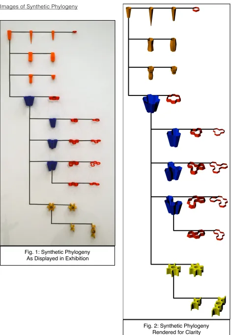
The first variations upon this root component explore forms that are composed of multiples of this root component (see the components in blue in the “phylogeny” in Fig. 2). These multiples allowed exploration of the unique nature of the structures made possible by a solid union of sets of the original components. Composite components using three and seven were made first with variations using four components produced after experimentation with the original composites. This also opened up some possibilities not available when making these combined forms using individual root components, because some of the internal structure of the monolithic combined component are removed allowing for hollow shell versions of these
composites and exposing the interior as possible interfaces.
Another avenue explored in producing new components was in varying the silhouette of the root component to create negative space which created interfacing opportunities for
components that had not been present in the previously designed components (see the components in orange in the “phylogeny” in Fig. 2). The first variation created was done by sectioning the root component into quarters. The middle two sections were removed and replaced by copies of the top component. A further variant was created by cutting this new component in half to produce a component that was essentially the root component with the middle two quarters removed and the two end quarters combined. Upon investigating the interplay of these components with the other components, I noticed another unique interfacing possibility when connecting the tapered quarter that was adjacent to the widest tapered quarter. This prompted the creation of components which took the root component, cut it in half, and then used two instances of half of the root attached by matching hexagonal surfaces to make convex and concave variants (see the components in the third row of the “phylogeny” in Fig. 2).
Images of Synthetic Phylogeny
[image:14.612.308.536.50.737.2]Fig. 1: Synthetic Phylogeny As Displayed in Exhibition
2.2 Production Details of Components
The previous section described the process of generating the design of the components, but the details in how the components are produced have direct influences on their nature and visual impact. Initially, molds were made from 3D printed plastic positives to slip cast the components. A small number of components cast from the RIT studio casting slip recipe were used in the final pieces, but in realizing the advantages of using FDM for production, I switched to 3D printing to produce the majority of components used in this body of work.
3D printed components were produced in a limited number of clay bodies designed to create a variety of surface characteristics using minimal glazing. I also worked to optimize the physical properties of these clay bodies for extrusion by the 3D printer. I chose to leave most of the components unglazed and relied on varying the atmosphere in the kiln firings to achieve the variety of surfaces in the work. Additional coloring is achieved through the application of oxide washes and underglazes. Glazes are used only for joining components in the firing, and the glaze chosen is a thin clear glaze so that it would have a minimal impact on the surface textures that result naturally from the 3D printing process.
One key ability leveraged heavily for this body of work is the ability to quickly vary the scale of the designed components. When primarily using slip casting to produce components, the only variation in scale came from using slip formulas with varying shrinkage rates and from differing the final firing temperatures. These variations were comparatively minor, with a range of up to 10% at most and typically only varying by 3%-5%. By using the 3D printer, I was able to achieve scales that ranged from 10% up to 210% of the original designed piece.
2.3 Methodologies for the Interfacing of Components
As components became available during the continual fabrication process, investigations began on the possibilities in joining them. Following the themes of modularization, I explored combining sets of components into formations containing novel structures of combinations of components that could be replicated and used as modular parts in larger designs. I explored forming these secondary composite components using both homogeneous and heterogeneous groups of components. I also paid attention to emergent interfacing possibilities that arose from the combination of components.
In viewing potential connections between components, I noticed another trend in my thinking about components. As I tested out how pieces fit together my mind would think about the interface between them as either symmetrical or asymmetrical. A symmetrical interfacing would be an interface between peers, with their interaction being similar to all components involved in that interaction. Symmetrical interfacing is typically between two components of similar design that are interacting with similar interfaces. In asymmetrical interfacing, I perceived that the interactions were different from the point of view of each interacting component. In these cases, each party in the interaction could be seen as the one providing an interface to the other that could not be taken advantage of by another instance of a similar component. For example, in the case of a nut and a bolt, they can both interact, but that interface could not form between two nuts or two bolts. Each of these types of interactions produced their own unique results. Symmetrical interfacing tends to join similar pieces together into more complex
3 Documentation of the Work:
Focal Pieces:
These pieces are presented on their own pedestal because they either embody more than one of the themes of the four categories of organization, or they embody an especially notable instance of a theme.
Atlas Spire
3D printed ceramic on acrylic base 10” x 10” x 12”
This piece combines the formation themes of a Framework in suggesting a spherical volume that is then uplifted by a spike like the Spire pieces
Hex Fractal
3D Printed Ceramics 11” x 6” x 3”
This piece was my initial exploration into the possibilities of having the same component produced in varying scales interacting with each other.
By exploring a basic fractal formation using the root form, this is a successful test case for
achieving complexity using only the root component and leveraging the possibilities enabled by using FDM technologies. Such structures require a
For my $n(1..4)
3D Printed Ceramics 12” x 12” x 4” as displayedTop Image is as photographed. Bottom Image is as presented in the Show
Diversity Colony
3D Printed Ceramics and Flameworked Glass 8” x 8” x 7”This specimen from the Colonies grouping is presented on its own because it exemplifies the potential of using diversity. It is the only piece in this body of work that uses glass in addition to ceramics.
The glass component was created from a press mold
designed from the seven-hex composite component specifically scaled and produced for use in the flame working process in forming borosilicate glass.
Colonies:
The image above shows how the pieces in categorized as “Colonies” were displayed for the show. These works were selected for exhibition because they each displayed novel
Colony 001
Slip Cast and 3D Printed Ceramic 12” x 12” x 3.5”This was the first colony created. The main motivation in the creation of this piece was to judge the feasibility of using the preexisting slip cast components with the newly created 3D printed components.
Also of note is that the 3D printed
components used in this work were early versions where I was still
Hex Coupler Core Colony
3D Printed Ceramics6” x 6” x 3.5”
At the core of this colony are a two layers of the hex coupler components that are based around the negative space between arrays of the root component. The use of these coupler components created opportunities for components to interact with the negative space that defines the couplers.
Radial Hex Shell Colony
3D Printed Ceramics12” x 12” x 2.5”
Elevated Colony
3D Printed Ceramic 11” x 11” x 5”4 Hex Composite Colony
3D Printed Ceramics6” x 7” x 3”
Spires:
4 Hex Radial Centralized Spire
3D Printed Ceramics8” x 8” x 12”
This piece was the first Spire formation produced. The spike is interfaced to the central cell of the 4 hex radially symmetric composite components.
With the components in this configuration, this spire is
4 Hex Radial Offset Spire
60 Degree Rotation
3D Printed Ceramics 9” x 9” x 9”
For this piece, the spike is interfaced with one of the outer hexagonal cells of the 4-cell composite
component, and the next component up is rotated by 60 degrees
4 Hex Radial Offset Spire
120 Degree Rotation
3D Printed Ceramics 10” x 10” x 12”For this piece, the spire is interfaced with one of the outer hexagonal cells of the 4-cell composite
component, and the next component up is rotated by 120 degrees.
The increased rotation makes it so that the layers immediately on top and below a component no longer overlap. This
decreases the perception of a helical structure. This piece, like the first piece in this category, is reminiscent of trees because the
Sequences:
3 Hex Cell Stack
3D Printed Ceramics 4” x 4” x 5”This formation, while being a stack of a scaled series, can also be viewed as a variant of the root
component that has been carved away.
4 Hex Cell Spiral (Black)
3D Printed Ceramics7” x 7” x 4.5”
This piece is the result of the joining of a series of radially symmetric four component composite of the root component. It shows one possible spiral progression for a scaled sequence of this component.
4 Hex Cell Stack
3D Printed Ceramics 7” x 7” x 3.5”4 Hex Cell Spiral (Buff)
3D Printed Ceramics 5” x 5” x 3”4 Hex Honeycomb Cell Stack
3D Printed Ceramics6” x 6” x 3”
This piece is another stack involving a progression of the four-component composite. In this stack, the components have a different scale rate and the components are infilled with a tessellation of hexagons.
4 Hex Cell Spiral (White)
3D Printed Ceramics6” x 6” x 3”
Frameworks:
Chirality
3D Printed Ceramics 14” x 8” x 1.5”
The term chirality is used in chemistry to denote differences between asymmetric molecules with similar compositions. “A chiral molecule/ion is non-superimposable on its mirror image.”
In this work, two pieces are compositionally similar, but their formation is notably
4 Hex Radial Framework
3D Printed Ceramics10” x 8” x 7”
4 Hex Offset Framework
3D Printed Ceramics11” x 6” x 6”
4 Analysis of Results:
4.1 Thoughts on the Implications of Using FDM Technology
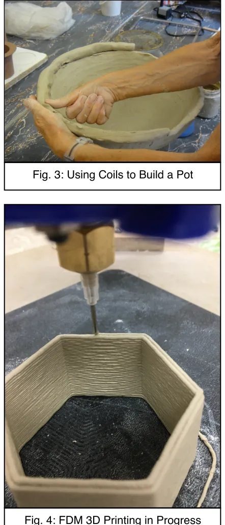
In watching the FDM 3D printing process, there are obvious parallels in the process of having a precisely controlled robot laying down a line of clay and the traditional process of coil potting (See Fig 3)5, which is one of the most basic techniques used in working with clay. This seemed
appropriately symbolic for the ceramics field given that its advancement has been rooted in a tradition of inventing and innovating new tools and
techniques.
While some have viewed the use of a 3D printer, which is essentially a robot, to make ceramic works as a travesty of a tradition of “handmade” ceramics, I see it as the latest tool in the field, that can track its lineage back through automated kiln controllers, mold based production, and the potter’s wheel all the way back to coil potting and making pinch pots. To prejudicially dismiss any 3D printed ceramics due to the way it was produced would be similar to dismissing any slip cast ceramics, any ceramics fired in a
programmable electric kiln, or any wheel thrown
ceramics purely based on the use of a tool or technique.
The frontier of using FDM technology is not
in using it to replicate what is possible with existing
techniques. This technology opens up the field of ceramics to possibilities that are impossible without it, just like advancements in kiln building and mold making made many once impossible things
possible. This body of work is just a beginning. This technology is still mostly terra incognita to many inside and outside the field of ceramics.
Pioneers and trailblazers in these areas deserve to be supported just as much as those who preserve and pass on the traditions of our field because all of those traditions were once frontiers, just as these cutting-edge techniques will one day become traditions.
Image by Image by Poupou l’quourouce. Usage under Creative Commons Attribution 3.0 5
[image:42.612.335.550.112.284.2]Unported License
[image:42.612.331.552.113.628.2]Fig. 3: Using Coils to Build a Pot
4.2 Thoughts on the Analytical Methodology Used in the Making of Sculpture
Similar to the questions raised by the use of FDM as a forming technique discussed above, the methodology of following the systematic analytical cycle used in making this body of
work, have some people questioning whether, conceptually, these pieces are better classified as
specimens rather than sculpture. The questions around which designation is most appropriate for the pieces in this body of work are curiously similar to the issues encountered by biological
taxonomists in classifying organisms in the natural world, a field which I have actively drawn
from for conceptual context in this body of work.
The field of taxonomy arose from a desire to classify the natural world, and I have incorporated themes from this field into my works. The synthetic “phylogeny” is a direct result of adapting taxonomic ideas into the creation of this exhibition. The exhibition is also presented in a format where the majority of the works are grouped by categories based upon their formation, which is also thematically similar to how taxonomists organize their specimens. Given this, it would be appropriate to designate the works in this exhibition as specimens, or even to draw further from taxonomic conventions and call the individual works “holotypes,” and the groupings “taxa.”
However, the scope of this work is not limited to the taxonomic, or even to the scientific. As with all organisms within the study of taxonomy, there are other terms and classifications that
are just as valid. I view the application of the more colloquial term of “sculpture” to my works as
a more accessible way for people to approach my works. If they wish to inquire further, they can
still access the more technical terminology, just like people who would seek further information
on a “monarch butterfly” can easily find that it is also known as “Danaus plexippus.”
4.3 The Emergence of Four Categories of Organization
While working on pieces for this show, four groupings emerged based upon the main interactions that most influenced and facilitated the creation of a piece. These groupings were used in organizing the works for exhibition, with each presenting a unique set of possibilities for
conceptual interpretation. Within the exhibition, works of the same grouping were placed next to each other on the same pedestal.
Frameworks:
These works were constructed by taking advantage of the dihedral angle formed by interfacing the tapered sides of each component. The five-degree taper present in the root component, and propagated to all subsequent components, encourages a natural curve in joints formed by connecting side faces. The manifestation of an implied spherical volume depends on
which faces are matched when two components are joined.
Works in this category are mainly formed from a core of symmetrical interfaces. The asymmetrical interfaces that do appear in these pieces are from components taking advantage of the emergence of interfaces in the formation made from the symmetrical interfacing of similar components.
Sequences:
These works explore what happens when instances of the same component are varied
in scale and combined. The scaling is similar to what happens in natural growth systems, so
many of these works resemble organic structures.
All the works in this category are formed from scaled versions of only one component. Similar to the works classified as frameworks, these works are formed by components that are peers, but unlike within the frameworks, there is variation in size between these peer
components.
I view the sequences as the result of organization within a set of individuals. These
pieces rely on their constituents to be ordered. These pieces also highlight that differences and variations within a group can be leveraged for the benefit of the group. And, it demonstrates that
these differences open up possibilities that are not available if all individuals were more homogeneous.
Spires:
These works focus on how a single component can provide a focus around which other components can coalesce. Although all components are essential to the work, these sculptures would not be possible without the unifying component at their center which serves as the interface point to the piece as a whole.
The unifying force of the central spike is from it providing asymmetrical interface points to each of the other components. It is the only component that touches every other component. Even though all the other components are related in their design, they do not directly interface with each other.
Because of this detachment between the scaled components, I think about whether the central component is exploitative in its relationships with the other components. However, if you were to separate the two classes of components, the spike alone would seem unexceptional, but the other components would form a sequence. It could be argued that the sequence formed would not be as compelling as the original spire, but it indicates that although the central spike has a lot to contribute to the spire, it seemingly needs the other components more than they need it. However, it is better for all involved that they work together.
Colonies:
This group of works explores the role of diversity in systems. Unlike the other groups, where there is a focus on one or two component designs that interact to form most of the work, these pieces focus on patterns that arise when all component types are available, and their use encouraged. These works showcase the many novel connections that can be formed through the interactions of diverse individuals coming together.
These works are the most complex to arise out of my investigations. They involve both
These works are also the most conceptually satisfying for me in that they show that diversity is a strength, and that within diversity, opportunities will arise for different types of components to contribute to something greater. There are components that are only found within colonies, and where they do appear, they play a key role in the work.
4.4 Thoughts on the Themes of Modularity
The motivations for pursuing modularity in the design and implementation of the work are intertwined with the methodologies and concepts upon which this body of work is built. Modularity in a design implicitly communicates the expectation of interactions with other modules. That intention is also reflected in the choice to use tools and techniques that are designed to produce multiples with great precision. These deliberate choices serve to facilitate the metaphor of social interactions between entities that are inherently social.
Great minds, both creative and scientific, have echoed this sentiment throughout the ages. From John Donne’s “No man is an island” to Carl Sagan’s “we are made of starstuff,” the truth of the universe is that everything is connected and is made from groupings. Everything is modular at some level and intended to interact, or has come about through interactions.
In focusing on a modular format, the work is an artistic attempt at reproducing results of the natural world in exploring the variety of possible formations that can arise from a simplified set of modules. The results are a validation of the magnitude of complexity that can arise from a controlled initial condition of limited interfaces. This abstraction also allows for the examination and analysis of emergent structures in these simplified systems to gain insights into the
emergent properties and behaviors of more complex natural systems.
There are conceptual implications related to the themes of the identity of the individual within a group that arise from my implementation choices. The impact and nature of these implications are at the heart of my explorations in this body of work. Does my choice to prioritize
dimensional precision in the production of “individuals” present a value judgement of conformity
versus uniqueness? How does diversity affect the success or failure of groups? From my own perspective as a person that has been an “other” in many aspects of my life, I am interested in whether certain conceptual metaphors would arise from this body of work.
nature. Ecosystems are composed of organisms that find a place where they can fit and thrive. In doing so, they transform their environment, and in doing so provide opportunities for other organisms to do the same. This is conceptually reassuring in that it illustrates that diversity has its strengths and that those strengths can be arrived at through the methodologies used and that those strengths also arise within natural systems.
4.5 Relationship to Existing Work
3D Printing in Ceramics
The technology for FDM using ceramics is still relatively new to the field of ceramic arts in that access to the technology is limited to those who can either construct their own equipment or to those who can afford one of the handful of commercially available printers.
Additionally, there is a
knowledge requirement where one must possess some specialized training in order to use the
equipment and the software that drives the equipment effectively.
Of those that have access to this equipment and expertise, there is a tendency to focus on forms enclosed by walls since the extrusion of the material lends itself most readily to enclosing volumes by building
vertical walls one thin layer on top of another. Much of the work of early adopters
of this technology to
ceramic work is made using this technique focuses on making vessels. Two notable people taking this
approach are Olivier van
Herpt in the Netherlands, and Bre Pettis who was
Overview of 3D printed work by Oliver Van Herpt
Image credits: Olivier van Herpt Year: 2014
Folded Bud Vase by Bre Pettis’ Bre&Co.
one of the original founders of MakerBot. Both produce works that
are recognizable as variations of traditional
functional ceramic vessels, and leverage the
capabilities of the
technology to explore new surfaces and forms.
Taking this a step further Bryan Czibesz and Shawn Spangler have
collaborated to incorporate 3D printed ceramic forms
with traditionally
constructed ceramic forms to make work that
references functional
ceramic forms, but makes a departure from some of the traditional functional values in ceramic vessels.
In my exploration of using FDM techniques, I have moved away from referencing ceramic vessels entirely. The forms in this body of work cannot easily be viewed as acting to contain any volume. Although some components on their own may suggest the form of a dish or a tray, their interactions within the whole of the combined piece counter their being perceived as
a functional container.
As the technology becomes more available and refined, artists who use it will find more opportunities to depart further from what is familiar. In a similar way to how slip casting started
out in the production of functional wares before moving on to find
sculptural applications, so too will FDM techniques slowly be adapted to newer areas once it is
better understood by
artists.
The Nature of the Digital in Art
With the scaling of digital processing power to a point where traditionally analog sensory data can be quantized to a digital representation in a
Bryan Czibesz and Shawn Spangler, Precis (Objects 38, 2, 3) 2015, from Re / Charting
Krater V.2 2017 by Michael Eden
developed the capability to convert what was once exclusively physical into a number. This has already happened to images and sound. With the advances in 3D scanning and printing, this is currently happening to the tactile physical object. This digitization is opening up a completely new set of tools for working with physical objects in the digital world.
In transforming a physical object into a number, we have opened up the full potential of digital processing to acting upon that object. The entirety of mathematical techniques computed at a speed limited only by the capacity of digital microprocessor technology is at the fingertips of anyone with the knowledge and drive to use it. Objects can be digitized and manipulated, or even constructed from scratch purely in the digital world, and then fabricated using rapid prototyping techniques.
One artist who is taking the most advantage of this has been Michael Eden, who digitizes traditional ceramic forms and alters them digitally before outputting them again as a changed physical object. His work showcases the possibilities of using technology to infuse objects with other data streams.
The work in this exhibition begins to take advantage of using digital processing to create and alter objects. Each component is created purely in the digital realm. The application of a scaling function to component designs is a basic mathematical function that would be difficult to perform on objects in the physical realm. Some of the components were mixed with other data streams to generate patterned infill, but those were very basic steps in mixing objects with other forms of data.
Currently, one of the greatest limitations to working digitally to produce physical objects is translating the object from the digital back to the physical. In order to produce the components for this body of work, I made innovations in the mechanics, the software, and the formulation of the clay that increased the accuracy and precision of the printed objects. The technical work in improving and refining the capabilities of ceramic FDM processes and materials will work to improve the process of translating digital designs into physical objects.
4.6 The Role of Aesthetic Evaluation in the Work
One goal of this exploration is to create compelling visual structures that draw the viewer in for closer examination. The question of whether the results of the methodology laid out for this examination can produce compelling visual structures is at the core of the investigation. Although, ultimately the judgment of whether I was successful or not is in the hands of the viewers, I used the following aesthetic guidelines when constructing and evaluating the work for exhibition.
Another guiding aesthetic principle for my evaluation was the search for the uncanny or the unexpected. This motivation balances our the motivations listed above in valuing the
emergence of familiar things. Sigmund Freud, in “Das Unheimliche” wrote about the uncanny as “the class of frightening things that leads us back to what is known and familiar.” This is shown in the tendency of drawings or models of people that approach realism too closely but not close enough to be completely accurate to fall into what is commonly known as the “uncanny valley.” Although I don’t believe that anything in this body of work falls into the uncanny valley, there are some aspects to applying digital technology to the traditions of ceramics some people find troubling, especially as the capabilities of technology move closer and closer to the ability of humans. Because of this, I found compelling anything that would take what is unexpected in the potentially troubling nature of digitally produced ceramics and lead the viewer back to the known in terms of aesthetic qualities. Due to the process in which they are created, digital objects are imbued with a set of expectations in the way they look and the way they act. Digital components are viewed as being discrete and quantized. They are also viewed as being rigid, which is also encouraged by the perceptions of the nature of ceramic objects. Ceramic objects are also seen as having weight and substance. I sought out properties in works that go against these
expectations. Of note, I pursued works that had a sense of lightness that goes against the perceptions of weight. I also pursued works that blended and flowed as they were counter to the perceptions of the discretization of digital objects. Finally, I favored works that had a tight sense of integration, where the gravitas of a piece as a whole countered the nature of the work being made of pieces as well as to counter the nature of the components making it up as being discrete in nature.
In both scientific and artistic perspectives, there is an appreciation to elegance that arises through simplicity. In math and physics, the admiration of the succinct and easy to follow proof of a seemingly complex phenomenon is like the admiration of a verse of poetry that can convey more emotion than a chapter of prose. This elegance is the motivation behind the works in the “Spires” and “Sequences” groupings and in the piece “Hex Fractal”. These works present a structure of form that is intricate and voluminous but still easily understandable upon closer examination. They are reminiscent of a poem in terms of their similar components which are suggestive of rhyming stanzas and also literally representative of a simply stated mathematical function.
When I am looking at artwork, I am especially drawn to what is new, novel, and unexpected. This is due to those properties being of indicative of potential research and
exploration in the scientific community, but in evaluating artwork, these properties become more subjective because, unlike science where the frontiers between what is known and what is being researched are recognized, artistic works and themes are so diverse that what might be familiar to one person may be completely new for another. This emphasis on the new and novel
is tempered by a tendency to avoid the overwhelming, which also depends on an individual’s
personal experiences. My own motivations to pursue the new and novel tend to lead me towards physical structures and conceptual themes that are especially complex, and are
teetering on the borderline of overwhelming for me. My liking of such works comes from a sense of delight that arises when I realize that I intrinsically understand these seemingly overwhelming
structures because I formulated the methods used in their construction. These works will potentially fall beyond the line of overwhelming for some, and I find myself debating whether I
value accessibility or personal appeal more. This dichotomy was at the forefront for the
aesthetically interesting in terms of their scale, structure, and organization, as well as most
conceptually compelling in what the unbridled diversity and symbiotic complexity synergistically
produces.
4.7 Areas For Further Research
Conceptual Explorations on Component Variation and Themes of Diversity
This body of work focuses on breaking down the complexities of group interactions down to simpler, more understandable components. As with most scientific pursuits, this initial
exploration involves making some assumptions of an ideal to make the testing and analysis more manageable. During the production of the components used in this show, imperfections
would arise due to various reasons such as loose mechanisms, material inconsistencies, air
pockets, controller glitches, etc. Because ceramics is naturally a medium that tends to display variations, most of these pieces were “within tolerances” to be used in this body of work.
However, there were many pieces that deviated outside of this range. They were “flawed” in that they did not accurately form the design that they were intended, but they were beautiful and visually captivating on their own.
Given that this body of work was an initial investigation, reconciling the implications of such deviations were outside of the scope of the work. However, furthering the investigation of the complexities of group dynamics, these pieces would make interesting conceptual additions. I hope to investigate further what these “out of spec.” pieces have to offer as components in larger works.
In addition to this, I see potential in finding a way to manage these variations. Many of the components that are “out of spec.” are difficult or impossible to reproduce because they are the result of an unforeseen failure, or series of failures, of material or equipment at precise times during their production. It isn’t necessary to have precise control of these conditions, but in order to pursue this line of investigation, one needs to increase the probability of such events
happening during production. There are interesting possibilities for developing and applying techniques that encourage different types of spontaneity and diversity in future works.
Another potential source of variation is utilizing alternate data streams while designing and fabricating components. It is possible to either alter a component design using another source of data, or to fit another source of data into a format that could interface with the existing components.
Continuing down the idea of exploring more variations, each component is the result of a number of influencing factors during its production. In this sense, each component is a product of the experiences that it goes through during its lifetime. I wish to explore this concept more by varying more of the conditions under which components are produced. Varying clay bodies, using different firings, applying different surface treatments, and even introducing different materials would have conceptual implications on the works, especially from the perspective of the role of experience in shaping an individual.
Conceptual Explorations on the Nature of the Individual
As mentioned above, a number of objects were created that were not appropriate for use
conceptually motivating, there is interesting research around treating and presenting these objects on their own in an appropriate context.
Also of interest is the exploration of potentially decreased opportunism when components are too similar and rigid. During the assembly of components, I noticed that variations that arose from the ceramic process, such as warpage or shrinkage, actually proved to be beneficial when attaching components. Sometimes, a slight warpage, or a slight shrinkage in individual components would combine in ways that benefited the larger work. Because of this, there are conceptual implications to the value of conformity and rigidity. One exploration to pursue is to find out what an optimal amount of variation may be and to examine what
conceptual implications that might have on the balance of the desires of individuals to be unique versus the desires to fit in.
Technical Explorations
When constructing and improving my ceramic extrusion 3D printer, my goal was to increase accuracy and precision, which is similar to many other people in designing and constructing such tools. The field is focused on making these tools simple and reliable. However, simple and reliable are not always interesting.
I have an idea for a mechanism to make it possible to introduce some spontaneous chaos to the system. Although it may seem like an oxymoron or a paradox, it is possible to build in a supplemental control panel that will allow an operator to influence certain behaviors of the printer in real-time during the printing process. This could potentially allow for the thoughtful exploration of a variation in the creation of 3D printed works.
There is also a lot of potential in the material being extruded. Since the construction
process is so different from other ceramic production processes, the physical requirements for
successfully 3D printed ceramics is different enough that clay bodies that would be difficult or
problematic for other forming processes could potentially be used in this process. Material
5 Technical Appendices
5.1 Clay Body and Glaze Formulations and Details
Cone 10 Translucent Porcelain for Printing
Mix 36g water for every 100g dry mix of above materials
This was adapted from a casting slip formula from Bryan Hopkins. The addition of the calcined Grolleg kaolin was to try and counteract some of the shrinkage encountered with this clay body. However, I believe this also increased the thixotropic nature of the clay to make it problematic for extrusion since it caused the water distribution within the clay to become inconsistent.
33COE Compatible Clay for Printing
Mix 36.5g water for every 100g dry mix of above materials
I had previously engineered a clay body that had a Coefficient of Expansion of 33 x 10 -7 / oC to be compatible with borosilicate lab glass. This formula is a variant of that formula that has been tuned for use in 3D printing. This clay extrudes beautifully when the water ratio is mixed just right. This clay formula was my workhorse for this project.
If designing for use in flame working glass, printing with infill provides a surprising amount of tolerance for thermal shock. Even if portions crack from shock, the larger piece will still likely hold together because of the internal structure.
I have fired this clay body up to cone 10. Pieces fired between cone 04 and cone 10 are suitable for joining with 33COE borosilicate glass. The body is mature when fired to cone 6.
Note, because of the low COE of this body, it does not perform well in salt/soda firings as the added sodium during the firing will flux the surface and greatly raise the COE of any exposed surface. This causes strain with the unexposed sections and will likely cause the piece to dunt.
NZ Monarch Kaolin 30
Calcined Grolleg 15
Minspar 20
Silica 25
Spodumene 22
Frit 3124 10
Grolleg 50
Yixing Inspired Printing Clay
Mix 42g water for every 100g dry mix of above materials
I created this clay body after researching recipes for Yixing clays. I wanted a darker clay body to contrast with the porcelain body and the 33COE body which both fire relatively white.
This clay body also prints beautifully when the water to dry materials ratio is mixed properly. The work for this show was fired between cone 6 and cone 10. Although the clay darkens to a rich color when reduced, firing this in electric oxidation will produce acceptable results. This clay also works well in soda firings.
SG-4 Clear “Joining” glaze
I got this formula from Peter Pincus and I mainly used this glaze to join pieces together. This glaze matures at cone 6 and does well in both oxidation and reduction.
Tile 6 20
OM 4 35
Redart 15
Barnard 10
Custer Feldspar 12
Silica 8
Frit 3195 22
Wollastonite 26.6
Nepheline Syenite 4
EPK 26.6
Silica 16
5.2 Notes on Calibrating Auger Based 3D Printer Extruders
One often overlooked aspect of ceramic based extrusion 3D printing is the calibration of
the clay feed rate of any stepper controlled extruder. Careful calibration of this feed rate was essential in being able to create the forms for this show. To understand how to properly calibrate
the extruder, one must first understand how all the parts of the process work in determining how
to drive the stepper that controls the extrusion of the clay.
In order for a design to be 3D printed, something has to translate the modeled design into a set of instructions for the printer. This task is performed by a program called the slicer, which takes in the modeled object as an STL file and turns that into a set of instructions for how the printer should move its stepper motors. Those instructions are usually referencing units defined in millimeters. In terms of moving the extruder head around, these instructions are specified in a cartesian coordinate system defined in millimeters.
This gets more complicated when generating the code to control the motor for extruding the build medium. The most commonly used slicer programs have been written with the
assumption that it is controlling a plastic filament FDM printer, where the user specifies the diameter of the filament. The slicer takes this information to calculate how much material is needed for a given distance traveled by the print head and translates that into an instruction to the extruder stepper motor to feed the proper length of filament, in millimeters, at the proper rate needed to provide the volume of material needed to build that segment of the model.
Within the printer’s “brain” is the information the printer needs to know to move the distance of the instructions generated by the slicer. It is the printer’s job to know how much to turn the individual motors to accurately follow the instructions generated by the slicer. This information is specific from printer to printer because it depends on how the drive mechanisms are engineered, but essentially the printer needs to know how many “steps” to move the motor in order to move it the distance that the slicer specified. From the perspective of controlling the extruder, the printer is translating motor “steps” to provide the specified length of material to lay down the correct volume of build material.
When dealing with an auger based extruder, this doesn’t match up exactly. We need to do some interesting translations to make sure the right amount of material gets placed to generate the object being printed. This is where calibration comes into play.
From here on out, I’m going to speak specifically about calibrating a printer running RepRap Marlin firmware, running off of GCODE generated from Slic3r, but the concepts should be applicable to other 3D printing setups.
Within the Marlin Configuration.h file, there is a section of definitions around stepper motor movements. The key setting for calibrating the stepper movements is
DEFAULT_AXIS_STEPS_PER_UNIT. This defines how many steps are required to move the stepper one unit, which is typically a millimeter. This setting is an array with the numbers corresponding to the steps needed for the x, y, z, extruder1, extruder2… motors respectively.
with a diameter of 1.75mm, the volume of material is ~2.4mm3. Ideally, one would calculate based upon thread pitch how many turns of the auger it takes to feed that volume of clay and then use that to determine how many steps it takes and enter that into the
DEFAULT_AXIS_STEPS_PER_UNIT spot for the extruder motor in the Marlin Config.h file. If this is calculated exactly, then you can enter 1.75mm into Slic3r as the filament diameter, and the generated GCODE will have the proper feed rates for building the desired object.
Alternately, you can “guess” at a number and put that into the Config.h file, then compensate by varying the filament diameter value in the Slic3r program.
The reality is likely that you will do a combination of these two techniques. You can do some basic math to get a ballpark number to put into DEFAULT_AXIS_STEPS_PER_UNIT and then tune the behavior of the extruder by tweaking the filament diameter parameter in Slic3r.
In my practical experience, reliable feed rate behavior varies with the tip size that I use. I
speculate that for finer gauge nozzles, the pressure needed to feed the material requires a
slightly increased feed rate. This can be done by either altering the filament diameter or the feed
multiplier parameter to compensate.
6 Bibliography
Aho, Alfred V., Ravi Sethi, and Jeffrey D. Ullman. Compilers, Principles, Techniques, and Tools. Reading, MA: Addison-Wesley Pub., 1986. Print.
Boorstin, Daniel J. The Discoverers. New York: Abrams, 1991. Print.
Feynman, Richard P., Ralph Leighton, and Edward Hutchings. "Surely You're Joking, Mr.
Feynman!": Adventures of a Curious Character. Place of Publication Not Identified: Sagebrush Bound, 1997. Print.
Gleick, James. Chaos: Making a New Science. London: Folio Society, 2015. Print.
Gonick, Larry, and Craig Criddle. The Cartoon Guide to Chemistry. New York: Harper Collins,
2008. Print.
John L. Hennessy and David A. Patterson. Computer Organization and Design. 1994. Print.
Lawrence, W. G., and R. R. West. Ceramic Science for the Potter. Oviedo, Fl.: Gentle Breeze Pub., 2001. Print.
Munroe, Randall. What If?: Serious Scientific Answers to Absurd Hypothetical Questions. London: John Murray, 2015. Print.
Padua, Sydney. The Thrilling Adventures of Lovelace and Babbage: The (mostly) True Story of