Civil Engineering Journal
Vol. 5, No. 10, October, 2019
Experimental Study of a Gas Engine-driven Heat Pump System for
Space Heating and Cooling
Wei Zhang
a, Xianzhao Yang
a, Tao Wang
a, Xueyuan Peng
a, Xiaolin Wang
b*a School of Energy and Power Engineering, Xi’an Jiaotong University, Xi’an 710049, China. b School of Engineering, University of Tasmania, Hobart, TAS 7001, Australia.
Received 10 July 2019; Accepted 14 September 2019
Abstract
In this paper, the performance of a gas engine-driven heat pump (GEHP) was experimentally studied for space heating and cooling. An experimental test facility was developed for this purpose. The effect of key parameters on system performance was investigated under both cooling and heating modes. The results showed that as the engine speed increased from 1400 to 2000 rpm, the cooling and heating capacities increased by 23% and 28.5%, respectively while the GEHP system Primary Energy Ratio (PER) decreased by 13.5% and 11.7% in the cooling and heating modes, respectively. The system PER in the cooling mode was found lower than that in the heating mode. This indicated that heat recovery from the engine cylinder and exhaust gas was very important for improving the GEHP system performance. In the heating mode, the ambient temperature and condenser water flow rate had a large effect on the system heating capacity and PER, and insignificant effect on the gas energy input. In the cooling mode, the chilled water inlet temperature showed a large effect on both cooling capacity and gas energy input while the chilled water flow rate had a large effect on cooling capacity and insignificant effect on the gas energy input.
Keywords: Gas Engine-Driven Heat Pump; Pace Cooling; Space Heating; PER; Heat Recovery.
1.
Introduction
Space cooling and heating are one of the largest energy consumptions in building sectors. Improving energy utilization efficiency of heating and cooling systems is one of the important ways to effectively utilize energy and reduce environmental pollution in this sector. Heat pump technology has been considered as a natural choice for space heating and cooling since it improves energy utilization efficiency and is environmentally friendly. Gas Engine-driven Heat Pump (GEHP) System has recently received much attention due to its high energy efficiency, especially for space heating [1].
Much research has focused on the study of the performance of GEHP systems for space heating. Zhang et al. [2] developed a steady-state model to investigate the performance of a GEHP system in heating mode. Results showed that engine waste heat provided about 1/3 of the total heating capacity. Engine speed largely affected the GEHP system performance while ambient temperature had little influence. Brenn et al. [3] compared the GEHP system performance with an electrically driven heat pump at hot water flow temperatures of 40 and 60 °C. The results showed that the GEHP system had almost the same efficiency and CO2 emissions as the electrically driven heat pump powered with electricity from the most modern natural gas-fired combined cycle power plants. Elgendy et al. [4] performed an experimental
* Corresponding author: [email protected]
http://dx.doi.org/10.28991/cej-2019-03091411
study on the GEHP performance for hot water supply. The system Primary Energy Ratio (PER) decreased as the hot water inlet temperature decreased, and engine speed increased. Yang et al. [5] studied the performance of a GEHP system working as a water heater in winter using a thermal model. The system PER and COP were found to increase with increasing the water flow rate and decrease with increasing the rotary speed and hot water temperature. The waste heat was effectively used in the defrost. Zhang et al. [6] experimentally studied a GEHP system with engine heat recovery and reported that the GEHP system PER and COP were largely affected by the engine speed and outdoor air temperature. The same finding was reported by Hu et al. [7].
Some researchers focus on the study of the GEHP system performance under cooling mode. Shin et al. [8] conducted dynamic modelling of a GEHP system during start-up in cooling mode. Variation of evaporator and condenser temperatures, shaft power consumption, engine fuel consumption and primary energy ratio of the system were evaluated. The comparison results showed that the proposed model could accurately predict system performance. Elgendy et al. [9] experimentally investigated the operating characteristics of a GEHP system used in water cooling without heat recovery. The effect of key parameters (e.g. evaporator water inlet temperature and flow rate, ambient air temperature, and engine speed) on the system performance was evaluated. A PER value of two was found for a wide range of operating conditions.
Many researchers investigated the performance of GEHP systems under both cooling and heating modes. Yang et al. [10] experimentally investigated the operating characteristics of a GEHP system under different working conditions. It showed that the GEHP saved energy, and the system PER was as high as 1.42. Xu and Yang [11] investigated the influence of various factors, including outdoor air temperature and humidity in winter and summer on the GEHP system performance. Results showed that the GEHP system could save more energy than the electrically driven heat pump. The system PER was higher in winter than that in summer. Sanaye and Chahartaghi [12] studied thermal modelling of a GEHP system and evaluated the heat pump and engine performances under different operating conditions. The same authors further studied the economics of using GEHP systems at various climate regions of Iran for both residential and commercial buildings, and for both heating and cooling purposes [13]. Liu et al. [14] experimentally investigated the influence of various factors on the performance of a GEHP system for cooling and hot water supply. The results showed that the effect of the evaporator water inlet temperature and gas engine speed on the system performance was more significant than the ambient air temperature. Zhang et al. [15] studied the GEHP system with energy storage system when supplying heating and cooling to the different types of buildings. The results showed that the GEHP integrated with an energy storage system could be used in different types of buildings with a more stable operation characteristic, higher PER and more suitable performance. Wan et al. [16] optimized the operating characteristics of a novel air conditioning system using mathematical modelling. This system used two power sources, the gas engine and dual-use motor, respectively. The results showed that the gas engine could always run in an economic zone with high thermal efficiency above 0.25 under different working modes.
From the above review, some experimental and theoretical investigation on the GEHP system performance has been conducted. However, very little literature discussed the GEHP system with heat recovery for both heating and cooling applications. In this paper, an experimental GEHP test rig was developed, and the performance of the GEHP system with heat recovery was experimentally studied for both heating and cooling applications. The effect of key parameters including engine speed, chilled water inlet and outlet temperature, ambient air temperature, condenser water flow rate on the system performance was evaluated. The research work provides useful information for theoretical study and GEHP system design and optimization.
2.
GEHP System Working Principle and Experimental Setup
The GEHP system studied in this paper is the same as that reported in the literature [6]. Figure 1 shows a schematic diagram of a GEHP system which consists of two main circulating cycles: primary heat pump cycle and engine coolant cycle.
In a cooling mode, the component (3) works as an evaporator where the refrigerant absorbs thermal energy from the chilled water and vaporizes. The chilled water is channelled to the building to provide cooling. The refrigerant vapour flows through the four-way valve (10) and enters the heat exchanger (11) where the waste heat is bypassed. Afterwards, the refrigerant vapour is absorbed by the compressor (2) and compressed. The high-temperature refrigerant flows to the component (7) which works as a condenser where the heat is rejected into the environment, and the refrigerant is cooled to a sub-cooled liquid. The liquid refrigerant bypasses the reservoir (5) and directly expands to the evaporator (3) for the next cycle. During this cooling mode, the cooling capacity is calculated based on the measured chilled-water flow rate, and the water temperature difference at the evaporator inlet and outlet. The compressor power consumption is calculated based on the refrigerant flow rate, and the refrigerant specific enthalpy change across the compressor. Also, in order to improve the energy utilization efficiency, the waste heat from the engine cylinder and exhaust gas is used to heat water to provide hot water for the building.
Engine coolant cycle: ethylene glycol-water is used as engine coolant to cool the engine. The coolant flows through the exhaust gas heat exchanger (14) where it absorbs heat from the exhaust gas and then the engine cylinder heat exchanger (15) where it cools engine to ensure the engine’s stable and efficient operation, and meanwhile it removes heat from the engine cylinder. In the heating mode, after the coolant receives the engine waste heat, it is introduced into the heat pump waste heat recovery exchanger (11) where it exchanges energy with the refrigerant from the evaporator and is cooled down for next cycle. The radiator (8) is an auxiliary heat exchanger for cooling engine coolant to prevent the engine coolant temperature from getting too high and hence affect the engine operation. In the cooling mode, after the coolant receives the waste heat, it is used to heat water to provide hot water to the buildings. In the engine coolant cycle, the coolant’s mass flow rate, the coolant temperatures at the inlet and outlet of the waste heat recovery exchanger (11), the exhaust gas heat exchanger (14) and the engine cylinder (15), are all measured. The heat recovered from the engine cylinder and exhaust gas is calculated based on the coolant mass flow rate and temperature differences.
[image:3.595.180.417.335.606.2]1. Engine, 2. Compressor, 3. Condenser, 4. Regulating valve, 5. Reservoir, 6. Throttle valve, 7. Evaporator, 8. Radiator, 9. Fan, 10. Four-way valve, 11. Waste heat exchanger, 12. Gas-liquid separator, 13. Three-way valve, 14. Exhaust gas heat exchanger, 15. Cylinder heat exchanger, 16. Pulley, 17. Torque meter, 18. Pressure reducing valve, 19. Gas cylinders.
Figure 1. A schematic diagram of a GEHP system with heat recovery
(with an accuracy ±0.5% of full scale, 0.3 – 12 m3/hr). The condenser/evaporator water flow rates are measured using the water flow meter, LDBE-40S (with an accuracy ±0.5% of full scale, 0.3 – 12 m3/hr). A mass flow meter DMF-1-1 with an accuracy ±0.2% of full scale (0 – 15 kg/hr) is used to measure the natural gas flow rate. The power consumption is measured using a torque tachometer (JN338) with an accuracy of 0.5 level (0 – 700 Nm). All the measured data are recorded in a data acquisition system over time. Table 1 lists the detailed information of the used measurement devices and their accuracies.
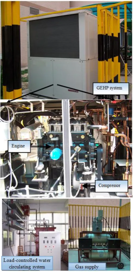
Figure 2. A picture of the studied GEHP Experimental setup
Table 1. Specification of the measurement devices used in the experimental study
Type Model Measurement range Accuracy
Temperature sensors PT100 -200~650 °C ±0.1 °C
Pressure transducers MPM480 0~3.5 MPa ±0.2% of full scale
Electromagnetic flow meter LDBE-40S-H2F120-30 0.3-12 m3/hr ±0.5% of full scale
Turbine flow meter LWGYC-10
0.2~1.2 m3/hr ±0.5% of full scale
0.2~1.5 m3/hr ±0.5% of full scale
Electromagnetic flow meter ZHLD-25 0.3-12 m3/hr ±0.5% of full scale
Gas mass flow meter DMF-1-1 0-15 kg/hr ±0.2% of full scale
[image:4.595.97.501.635.779.2]3.
Performance Calculation
The performance of the GEHP system can be calculated from measured data for R407c operating pressures and temperatures, as well as ethylene glycol-water and condenser water temperatures. The heating capacity 𝑄̇ℎ and cooling capacity 𝑄̇𝑐 are calculated based on the condenser or evaporator water flow circuit using Equations 1 and 2, respectively: For heating mode:
𝑄̇
ℎ= 𝑚̇
𝑤𝑐⋅ 𝑐
𝑝−𝑤⋅ (𝑇
𝑤𝑐−𝑜𝑢𝑡− 𝑇
𝑤𝑐−𝑖𝑛)
(1)
For cooling mode:
𝑄̇
𝑐= 𝑚̇
𝑤𝑒⋅ 𝑐
𝑝−𝑤⋅ (𝑇
𝑤𝑒−𝑜𝑢𝑡− 𝑇
𝑤𝑒−𝑖𝑛)
(2)
Where
𝑚̇
𝑤𝑐,𝑚̇
𝑤𝑒is condenser and evaporator water flow rate, respectively. cp-w is specific heat of condenser and evaporator water at constant pressure. Twc-out and Twc-in are water temperature at the condenser inlet and outlet, respectively. Twe-out and Twe-in are water temperature at the evaporator inlet and outlet, respectively.The heat recovered from the engine cylinder and exhaust gas 𝑄̇𝑒𝑥ℎ is calculated based on the ethylene glycol-water flowing circuit using Equations 3 and 4, respectively:
For heating mode:
𝑄̇
𝑒𝑥ℎ= 𝑚̇
𝑔𝑤,𝑒𝑥ℎ⋅ 𝑐
𝑝,𝑔𝑤⋅ (𝑇
𝑔𝑤,𝑒𝑥ℎ,3− 𝑇
𝑔𝑤,𝑒𝑥ℎ,4)
(3)
For cooling mode:
𝑄̇
𝑒𝑥ℎ= 𝑚̇
𝑔𝑤,𝑒𝑥ℎ⋅ 𝑐
𝑝,𝑔𝑤⋅ (𝑇
𝑔𝑤,7− 𝑇
𝑔𝑤,5)
(4)
Where
𝑚̇
𝑔𝑤,𝑒𝑥ℎis ethylene glycol-water flow rate,
c
p,gwis specific heat of ethylene glycol-water at constant
pressure, and 𝑇𝑔𝑤,𝑒𝑥ℎ,3, 𝑇𝑔𝑤,𝑒𝑥ℎ,4, 𝑇𝑔𝑤,5, 𝑇𝑔𝑤,,7is ethylene glycol-water temperature at the measurement points 3, 4, 5 and 7 as indicated in Figure 1.The compressor power consumption, Wcomp is calculated by using Equations 5, 6, 7, as follows:
𝑊
𝑐𝑜𝑚𝑝= 𝑚̇
𝑟𝑒𝑓⋅ (ℎ
𝑟𝑒𝑓,𝑜𝑢𝑡− ℎ
𝑟𝑒𝑓,𝑖𝑛)/𝜂
𝑐𝑜𝑚𝑝(5)
ℎ
𝑟𝑒𝑓,𝑜𝑢𝑡= 𝑓(𝑃
𝑐𝑜𝑚𝑝,𝑜𝑢𝑡, 𝑇
𝑐𝑜𝑚𝑝,𝑜𝑢𝑡)
(6)
ℎ
𝑟𝑒𝑓,𝑖𝑛= 𝑓(𝑃
𝑐𝑜𝑚𝑝,𝑖𝑛, 𝑇
𝑐𝑜𝑚𝑝,𝑖𝑛)
(7)
Where 𝑚̇𝑟𝑒𝑓is refrigerant flow rate, href,in and href,out are refrigerant specific enthalpy at the compressor inlet and outlet, respectively. The specific enthalpy is obtained from the NIST database according to the temperatures and pressures.
Pcomp,in, Pcomp,out, Tcomp,in and Tcomp,out are the pressures and temperatures at the compressor inlet and outlet, respectively.
𝜂𝑐𝑜𝑚𝑝is the compressor mechanical efficiency and is set at 0.96 for this study according to the manufacturer’s product specification.
The total energy consumption 𝐸̇𝑛𝑔 is calculated based on the natural gas flow rate 𝑚̇𝑛𝑔and low heating value, LHV using Equation 8:
𝐸̇
𝑛𝑔= 𝑚̇
𝑛𝑔⋅ 𝐿𝐻𝑉
(8)
The COP of the heat pump and the PER of the GEHP system are calculated by Equations 9 and 10:
For heating:
𝑃 =
𝑄̇ℎ𝑊𝑐𝑜𝑚𝑝
,
𝑃𝐸𝑅 =
𝑄̇ℎ𝐸̇𝑛𝑔
(9)
For cooling:
𝑃 =
𝑄̇𝑐𝑊𝑐𝑜𝑚𝑝
,
𝑃𝐸𝑅 =
𝑄̇𝑐𝐸̇𝑛𝑔
(10)
In the cooling mode, if the waste heat is used to provide hot water or other heating purposes for the building, the total system PERtotal is calculated by Equation 11:
𝑃𝐸𝑅 =
𝑄̇𝑐+𝑄𝑒𝑥ℎ𝐸̇𝑛𝑔
(11)
In the experimental study, error analysis is always very important. The accuracy of the sensors has been presented in Table 1. The measurement errors for heating capacity, cooling capacity, COP and PER caused by the accuracy of the sensors can be calculated from error propagation using the Kline and McClintock method [17] as expressed by Equation 12:
𝑤
𝑅= [(
𝜕𝑥𝜕𝑅 1𝑤
1)
2
+ (
𝜕𝑥𝜕𝑅2
𝑤
2)
2+⋅⋅⋅ + (
𝜕𝑥𝜕𝑅 𝑛𝑤
𝑛)
2
]
1/2(12)
function of the independent variables x1, x2, …, xn. Using this equation, the uncertainties for the heating capacity, cooling capacity, recovered heat capacity, COP and PER are ±3.5%, ±3.5%, ±7.5%, ±4.2%, and ±4.5%, respectively.
4.
Results and Discussion
[image:6.595.76.521.180.324.2]The performance of the GEHP system was studied for both cooling and heating operating modes under different operating conditions. Figure 3 shows the experimental flow chart. In order to minimize the measurement error, the experiments were repeated at least three times at each operating condition. Table 2 listed the GEHP experimental operating conditions in this study.
Figure 3. Experimental flow chart
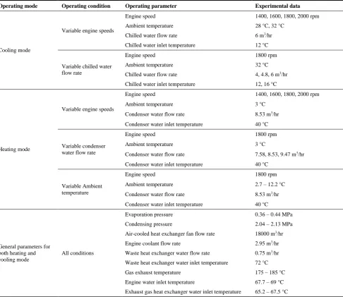
Table 2. Experimental operating conditions
Operating mode Operating condition Operating parameter Experimental data
Cooling mode
Variable engine speeds
Engine speed 1400, 1600, 1800, 2000 rpm
Ambient temperature 28 °C, 32 °C
Chilled water flow rate 6 m3/hr
Chilled water inlet temperature 12 °C
Variable chilled water flow rate
Engine speed 1800 rpm
Ambient temperature 32 °C
Chilled water flow rate 4, 4.8, 6 m3/hr
Chilled water inlet temperature 12, 16 °C
Heating mode
Variable engine speeds
Engine speed 1400, 1600, 1800, 2000 rpm
Ambient temperature 3 °C
Condenser water flow rate 8.53 m3/hr
Condenser water inlet temperature 40 °C
Variable condenser water flow rate
Engine speed 1800 rpm
Ambient temperature 3 °C
Condenser water flow rate 7.58, 8.53, 9.47 m3/hr
Condenser water inlet temperature 40 °C
Variable Ambient temperature
Engine speed 1800 rpm
Ambient temperature 2.7 – 12.2 °C
Condenser water flow rate 8.53 m3/hr
Condenser water inlet temperature 40 °C
General parameters for both heating and cooling mode
All conditions
Evaporation pressure 0.36 – 0.44 MPa
Condensing pressure 2.04 – 2.13 MPa
Air-cooled heat exchanger fan flow rate 18000 m3/hr
Engine coolant flow rate 2.95 m3/hr
Waste heat exchanger water flow rate 0.75 m3/hr
Waste heat exchanger water inlet temperature 72 °C
Gas exhaust temperature 175 – 185 °C
Engine water inlet temperature 67.7 – 69 °C
[image:6.595.58.545.350.771.2]4.1. Performance Analysis in Cooling Mode
[image:7.595.135.463.206.418.2]Figure 4 shows the variation of the cooling capacity and gas energy under different engine speeds and ambient temperatures. The chilled water inlet temperature and flow rate are maintained at 12 °C and 6 m3/hr, respectively. As the engine speed increases from 1400 to 2000 rpm, the gas energy, and cooling capacity is increased by 43% and 23%, respectively. This is because an increase in engine speed increases the gas flow rate. Meanwhile, it also increases the compressor rotational speed which increases the refrigerant flow rate and cooling capacity. As the ambient temperature increases from 28 to 32 °C, both cooling capacity and gas energy decreases. For gas energy, it is due to the gas density which reduces with increasing the ambient temperature. Hence the gas mass flow rate decreases leading to a decrease in gas energy. For the cooling capacity, the increase in ambient temperature causes a rise in the condenser pressure and temperature due to the air-cooling. Therefore, the compressor power consumption increases and the cooling capacity decreases in the refrigeration system.
Figure 4. Cooling capacity and gas energy under ambient temperatures of 28 and 32 °C
Furthermore, the increase of gas energy is much higher than the cooling capacity as the engine speed increases. This explains the decrease in system PER as shown in Figure 5. As the engine speed increased from 1400 to 2000 rpm, the GEHP system PER decreased by 13.5%. Figure 5 also showed that the refrigeration system COP decreased with engine speed. This was because the increase in compressor power consumption is higher than the cooling capacity. Moreover, it was shown that the system PER was less than 1 for the cooling mode in all studied conditions. This indicated that much energy was lost from the engine. As shown in Table 2, the gas exhaust temperature is about 175 – 185 °C and engine water inlet temperature is between 67.7 to 69 °C. Such a high temperature could be recovered to provide hot water for buildings.
Figure 5. Refrigeration system COP and GEHP system PER under ambient temperatures of 28 and 32 °C
0 5 10 15 20 25 30 35 40 45
0 5 10 15 20 25 30 35 40 45
1300 1400 1500 1600 1700 1800 1900 2000 2100
G
a
s
e
n
e
rg
y
(k
W
)
C
o
o
li
n
g
c
a
p
a
c
ity
(k
W
)
Engine speed (rpm)
Cooling capacity at 28°C Gas energy at 28 °C Cooling capacity at 32 °C Gas energy at 32 °C
0.3 0.5 0.7 0.9 1.1 1.3 1.5
1.0 1.5 2.0 2.5 3.0 3.5 4.0 4.5
1300 1400 1500 1600 1700 1800 1900 2000 2100
PER
C
O
P
Engine speed (rmp)
COP at 28 °C COP at 32 °C
[image:7.595.133.460.547.761.2]Figure 6 shows the potential recovered thermal energy and system total PER when the recovered thermal energy is considered. The total potential recovered thermal energy ranged between 18 kW at the engine speed of 1400 rpm and 26 kW at the engine speed of 2000 rpm. The system PER increased from between 0.96 and 0.83 to between 1.5 and 1.36 when the waste heat was recovered. This demonstrated that it was important to recover the waste thermal energy from the exhaust gas and engine cylinder to improve energy utilization efficiency even the GEHP is running under cooling mode.
Figure 6. Variation of potential recovered energy and system total PER under ambient temperatures of 28 and 32 °C
[image:8.595.127.472.524.747.2]Figures 7 to 9 show the effect of the chilled water flow rate on the performance of the GEHP system. The engine speed and ambient temperature are maintained at 1800 rpm and 32 °C, respectively. As shown in Figure 7, as the chilled water flow rate increases, the cooling capacity increases remarkably while the gas energy does not show a significant change. This can be explained from the conventional vapour compression refrigeration system. As the chilled water flow rate increases, the average chilled water temperature between the evaporator inlet and outlet increases. This leads to a rise in the refrigerant evaporation temperature which increases the cooling capacity. However, this effect on the engine is very small so that the gas energy does not change significantly. Furthermore, due to an increase in refrigerant evaporation temperature, the refrigeration pressure difference across the compressor reduces and hence, the compressor power consumption decreases. These two factors increase both the refrigeration system COP and the GEHP system PER as shown in Figure 8.
Figure 7. Variation of cooling capacity and gas energy under chilled water inlet temperatures of 12 and 16 °C
0.4 0.6 0.8 1.0 1.2 1.4 1.6 10 15 20 25 30 35 40
1300 1400 1500 1600 1700 1800 1900 2000 2100
Sy s te m to ta l PER H e a t re c o v e ry e n e rg y (k W )
Engine speed (rpm)
Heat recovery at 28 °C
Heat recovery at 32 °C
System total PER at 28 °C
System total PER at 32 °C
25 27 29 31 33 35 37 39 41 25 27 29 31 33 35 37 39 41
3.5 4.0 4.5 5.0 5.5 6.0 6.5
G a s e n e rg y (k W ) C o o li n g c a p a c ity (k W )
Chilled water flow rate (m3/h)
Cooling capacity at 12 °C
Cooling capacity at 16 °C
Gas energy at 12 °C
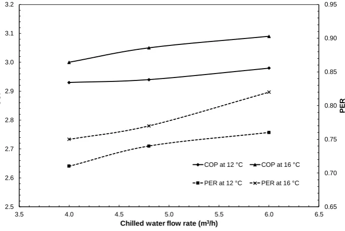
Figure 8. Variation of refrigeration system COP and system PER under chilled water inlet temperatures of 12 and 16 °C
Figures 7 and 8 also shows that the cooling capacity and gas energy increase as the chilled water inlet temperature increases from 12 to 16 °C. This can also be explained from the conventional vapour compression refrigeration system. As the chilled water inlet temperature increases, the refrigeration evaporation temperature increases, which increases the cooling capacity and reduces the compressor power consumption per unit refrigerant. Therefore, both cooling capacity and COP of the refrigeration system increases. Due to the increase in cooling capacity, the refrigerant mass flow rate in the system also increases, which requires high compression power for the whole cycle. The increase in total compression power consumption requires more power input from the gas engine. However, due to high refrigeration system performance, the increase in gas energy is much smaller than the increase in the cooling capacity. Therefore, the GEHP system PER increases.
[image:9.595.120.479.503.735.2]Figure 9 shows the potential available thermal energy for providing hot water to the building and potential system total PER. As the chilled water flow rate increases, the refrigeration system is more efficient, and more gas energy is utilized. Therefore, the engine system performance also increases and hence, the potential available thermal energy reduces. However, due to an increase in cooling capacity as shown in Figure 7, the overall system total PER increases.
Figure 9. Variation of the recovered heat and system total PER under chilled water inlet temperatures of 12 and 16 °C
0.65 0.70 0.75 0.80 0.85 0.90 0.95
2.5 2.6 2.7 2.8 2.9 3.0 3.1 3.2
3.5 4.0 4.5 5.0 5.5 6.0 6.5
PER
C
O
P
Chilled water flow rate (m3/h)
COP at 12 °C COP at 16 °C
PER at 12 °C PER at 16 °C
1.10 1.15 1.20 1.25 1.30 1.35 1.40
18 19 20 21 22 23 24 25 26
3.5 4.0 4.5 5.0 5.5 6.0 6.5
Sy
s
te
m
to
ta
l
PER
R
e
c
o
v
e
re
d
h
e
a
t
(k
W
)
Chilled water flow rate (m3/h)
Recovered heat at 12 °C
Recovered heat at 16 °C
System total PER at 12 °C
4.2. Performance Analysis in Heating Mode
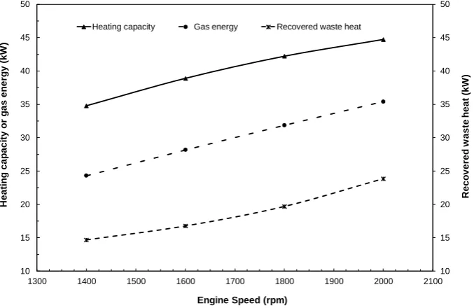
[image:10.595.129.468.195.415.2]Figure 10 shows the variation of the heating capacity, gas energy and utilization of waste heat under different engine speeds. The ambient temperature is 3 °C. The condenser water inlet temperature and the flow rate are maintained at 40 °C and 8.53 m3/hr, respectively. As the engine speed increases from 1400 to 2000 rpm, the heating capacity, gas energy and recovered waste heat are increased by 28.5%, 45.7%, and 62.5%, respectively. This increasing trend is consistent with the finding in the literature [10]. This is mainly due to the gas mass flow rate. With increasing the engine speed, the gas mass flow increases in the engine, which increases the gas energy input. Meanwhile, a rise in engine speed directly increases the compressor speed in the heat pump, which increases the refrigerant mass flow rate. Therefore, the heating capacity increases. On the other hand, the energy absorbed in the evaporator and waste heat exchanger by the refrigerant increases, which in-turn recovers more thermal energy.
Figure 10. Variation of the cooling capacity, gas energy and recovered waste heat under different engine speeds
[image:10.595.123.468.543.768.2]Figure 11 shows the variation of the heat pump COP and the GEHP system PER. Both COP and PER were found to decrease with increasing the engine speed. This trend is also consistent with the finding in the literature [10]. This is mainly due to the operating characteristics of the heat pump. As the compressor speed increases, the refrigerant mass flow increases, which lowers the evaporation pressure and increases the condensation pressure. Therefore, the compressor power consumption increasing rate is higher than the increasing rate of the heating capacity. Hence, the heat pump COP drops. As shown in Figure 10, the increasing rate of heating capacity is smaller than the increasing rate of gas energy, which leads to a decrease in the GEHP system PER.
Figure 11. Variation of the heat pump COP and GEHP system PER under different engine speeds
10 15 20 25 30 35 40 45 50 10 15 20 25 30 35 40 45 50
1300 1400 1500 1600 1700 1800 1900 2000 2100
R e c o v e re d w a s te h e a t (k W ) H e a ti n g c a p a c ity o r g a s e n e rg y (k W )
Engine Speed (rpm)
Heating capacity Gas energy Recovered waste heat
1.0 1.1 1.2 1.3 1.4 1.5 1.6 1.7 1.8 1.9 2.0 1.0 1.5 2.0 2.5 3.0 3.5 4.0 4.5 5.0 5.5
1300 1400 1500 1600 1700 1800 1900 2000 2100
PER
C
O
P
Engine Speed (rpm)
Another interesting finding is that the GEHP system PER in the heating mode (e.g. between 1.25 and 1.4 in Figure 11) is much higher than that in the cooling mode (e.g. 0.7 - 0.9 in Figure 5) without heat recovery. This is consistent with the finding reported in the literature [11]. This is mainly because the waste heat from the exhaust gas and engine cylinder is effectively recovered in the heating mode. As presented in Figures 6 and 9, if the waste heat from the engine cylinder and exhaust gas could be used to provide hot water or for other heating purposes, the system PER increased from between 0.7 and 0.9 to between 1.25 and 1.45 in the cooling mode. This PER in the cooling mode with heat recovery is similar to the GEHP system PER in the heating mode, which indicated that waste heat recovery is very important in the GEHP system for both cooling and heating modes.
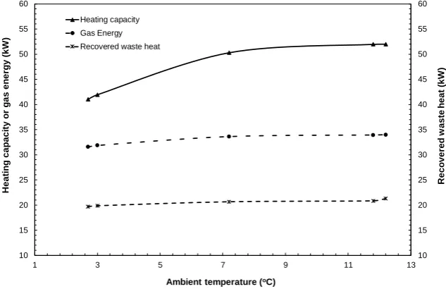
[image:11.595.138.455.328.533.2]Figures 12 and 13 show the effect of ambient temperature on the GEHP system performance. The engine speed is 1800 rpm. The condenser water flow rate and inlet temperature are 8.53 m3/hr and 40 °C, respectively. As shown in Figure 12, as the ambient temperature increases from 2.7 to 12.2 °C, the heating capacity increases by 27% while the gas energy and waste heat recovery only increase by 7.7% and 8%, respectively. This is consistent with the finding in the literature [2]. This is because the increase in ambient temperature increases the refrigeration evaporation temperature, pressure and mass flow rate in the evaporator. The rise in the refrigerant mass flow rate increases the heating capacity and compressor power consumption. Meanwhile, the increase in refrigeration pressure reduces the compression power consumption, which offsets an increase in compressor power consumption caused by an increase in the refrigerant mass flow rate. Therefore, the increase in compressor power consumption is much smaller than heating capacity. This small increase in compressor power consumption leads to a gentle increment of gas energy as shown in Figure 12. Due to these reasons, the heat pump COP shows a much larger increment than the GEHP system PER in Figure 13. As the ambient temperature increases from 2.7 to 12.2 °C, the heat pump COP is increased by 23% while the GEHP system PER is increased by 17%.
Figure 12. Effect of ambient temperature on heating capacity, gas energy and recovered waste heat
Figure 13. Effect of ambient temperature on the heat pump COP and GEHP system PER
10 15 20 25 30 35 40 45 50 55 60 10 15 20 25 30 35 40 45 50 55 60
1 3 5 7 9 11 13
R e c o v e re d w a s te h e a t (k W ) H e a ti n g c a p a c ity o r g a s e n e rg y (k W )
Ambient temperature (oC)
Heating capacity Gas Energy Recovered waste heat
1.2 1.4 1.6 1.8 2.0 2.2 2.4 3.0 3.5 4.0 4.5 5.0 5.5 6.0
1 3 5 7 9 11 13
PER
C
O
P
Ambient temperature (oC)
Figures 14 and 15 show the effect of condenser water flow rate on the performance of the GEHP system. The engine speed is 1800 rpm. The ambient temperature and the condenser water inlet temperature are maintained at 3 °C and 40 °C, respectively. As shown in Figure 14, as the condenser water flow rate increases from 7.58 to 9.47 m3/hr, the heating capacity, gas energy and recovered waste heat are increased by 6.6%, 1.3, and 0.9%, respectively. This indicates that the condenser water flow rate has small effects on the GEHP system performance. As the condenser water flow rate increases, the condensation temperature, and pressure drop. The refrigerant specific enthalpy difference across the condenser increases and hence the heating capacity increases. The drop of the refrigeration pressure also leads to a reduction of the compressor power consumption which offsets by an increase in the compressor power consumption caused by the refrigerant mass flow rate. The change in compressor power input also causes an increase in gas energy. Therefore, both heat pump COP and GEHP system PER increase gently as shown in Figure 15.
Figure 14. Effect of the condenser water flow rate on the heating capacity, gas energy and recovered waste heat
Figure 15. Effect of the condenser water flow rate on the heat pump COP and GEHP system PER
5. Conclusions
The performance of a GEHP system was experimentally investigated for both cooling and heating modes. The effect of engine speed, chilled water inlet temperature and flow rate on the system performance was studied in the cooling mode, and the effect of engine speed, ambient temperature and condenser water flow rate on the system performance was evaluated in the heating mode. The following conclusions were obtained:
The PER of the GEHP system in cooling mode in summer conditions was lower than that in the heating mode in winter conditions. The analysis showed that heat recovery in the GEHP system was very important for improving
10 15 20 25 30 35 40 45 50
10 15 20 25 30 35 40 45 50
7.0 7.5 8.0 8.5 9.0 9.5 10.0
R
e
c
o
v
e
re
d
w
a
s
te
h
e
a
t
(k
W
)
H
e
a
ti
n
g
c
a
p
a
c
ity
(k
W
)
Condenser water flow rate (m3/h)
Heating capacity Recovered waste heat Gas energy
0.8 1.0 1.2 1.4 1.6 1.8 2.0 2.2
1.0 1.5 2.0 2.5 3.0 3.5 4.0 4.5 5.0 5.5 6.0
7.0 7.5 8.0 8.5 9.0 9.5 10.0
PER
C
O
P
Condenser water flow rate (m3/h)
the energy utilization efficiency in both cooling and heating modes.
The engine speed had a similar impact on the GEHP system performance for both cooling and heating modes. As the engine speed increased from 1400 to 2000 rpm, the heating capacity increased by 28.5% and the system PER dropped by 11.7% in the heating mode while the cooling capacity increased by 23% and the system PER dropped by 13.5% in the cooling mode.
In the cooling mode, as the ambient temperature increased from 28 to 32 °C, the cooling capacity and system PER decreased by up to 7% and 12%, respectively. However, in the heating mode, as the ambient temperature increased from 2.7 to 12.2 °C, the heating capacity and system PER increased by 27% and 18%, respectively.
In the cooling mode, an increase in the chilled water flow rate and inlet temperature improved both system cooling capacity and PER. In the heating mode, an increase in the condenser water flow rate slightly improved the system heating capacity and PER.
These experimental analyses provide useful information for theoretical study as the experimental results proved the theoretical finding from numerical simulations in the literature.
6. Conflicts of Interest
The authors declare no conflict of interest.
7. References
[1] Lian, Z., Park, S., Huang, W., Baik, Y., and Yao, Y. “Conception of Combination of Gas-engine-driven Heat Pump and Water-loop Heat Pump System.” International Journal of Refrigeration 28, no. 6 (September 2005): 810–819. doi:10.1016/j.ijrefrig.2005.02.004.
[2] Zhang, R., Lu, X., Li, S., and Gu, A. “Analysis on the Heating Performance of a Gas Engine Driven Air to Water Heat Pump Based on a Steady-state Model.” Energy Conversion and Management 46, no. 11-12 (July 2005): 1714–1730. doi:10.1016/j.enconman.2004.10.009.
[3] Brenn, J., Soltic, P., and Bach, C. “Comparison of Natural Gas Driven Heat Pumps and Electrically Driven Heat Pumps with Conventional Systems for Building Heating Purpose.” Energy and Building 42, no. 6 (June 2010): 904–908. doi:10.1016/j.enbuild.2009.12.012.
[4] Elgendy, E., Schmidt, J., K halil, A., and Fatouh, M. “Performance of a Gas Engine Driven Heat Pump for Hot Water Supply Systems.” Energy 36, no. 5 (May 2011): 2883–2889. doi:10.1016/j.energy.2011.02.030.
[5] Yang, Z., Wang, W., and Wu, X. “Thermal Modeling and Operating Tests for a Gas-engine Driven Heat Pump Working as a Water Heater in Winter.” Energy and Buildings 58 (March 2013): 219–226. doi:10.1016/j.enbuild.2012.10.049.
[6] Zhang, Wei, Tao Wang, Sulu Zheng, Xueyuan Peng, and Xiaolin Wang. “Experimental Study of the Gas Engine Driven Heat Pump with Engine Heat Recovery.” Mathematical Problems in Engineering 2015 (2015): 1–10. doi:10.1155/2015/417432. [7] Hu, B., Li, C., Yin, X., Cao, F., and Shu, P.. “Thermal Modeling and Experimental Research of Gas Engine-driven Heat Pump in
Variable Condition.” Applied Thermal Engineering 123 (August 2017): 1504-1513. doi:10.1016/j.applthermaleng.2017.05.189. [8] Shin, Y., Yang, H., Tae, C.S., Jang, C.Y., and Cho, S. “Dynamics Modeling of a Gas Engine-driven Heat Pump in Cooling Mode.”
Journal of Mechanical Science and Technology 20, no. 2 (February 2006): 278–285. doi:10.1007/bf02915830.
[9] Elgendy, E., and Schmidt, J.. “Experimental Study of Gas Engine Driven Air to Water Heat Pump in Cooling Mode.” Energy 35, no. 6 (June 2010): 2461–2467. doi:10.1016/j.energy.2010.02.040.
[10] Yang, Z., Cheng, H., Zhang, S.G., and Xie, Y.B. “Experimental Research of a Compressive Heat Pump Air-condition System Driven by Gas Engine.” Journal of Engineering Thermophysics, 24 (November 2003): 920–922.
[11] Xu, Z., and Yang, Z. “Saving Energy in the Heat-pump Air Conditioning System Driven by Gas Engine.” Energy and Building 41, no. 2 (February 2009): 206–211. doi:10.1016/j.enbuild.2008.09.001.
[12] Sanaye, S., and Chahartaghi, M. “Thermal Modeling and Operating Tests for the Gas Engine-driven Heat Pump Systems.” Energy 35, no. 1 (January 2010): 351–363. doi:10.1016/j.energy.2009.10.001.
[13] Sanaye, S., Meybodi, M. A., and Chahartaghi, M. “Modeling and Economic Analysis of Gas Engine Heat Pumps for Residential and Commercial Buildings in Various Climate Regions of Iran.” Energy and Building 42, no. 7 (July 2010): 1129–1138. doi:10.1016/j.enbuild.2010.02.004.
[15] Zhang, Q., Yang, Z., Li, N., Feng, R., Gao, Y. “The Influence of Building Using Function on the Operating Characteristics of the Gas Engine Driven Heat Pump with Energy Storage System (ESGEHPs).” Energy & Buildings 167 (May 2018):136–151. doi:10.1016/j.enbuild.2018.02.039.
[16] Wan, X., Cai, L., Yan, J., Ma, X., Chen, T., Zhang, X. “Power Management Strategy for a Parallel Hybrid-power Gas Engine Heat Pump System.” Applied Thermal Engineering 110 (January 2017):234–243. doi:10.1016/j.applthermaleng.2016.07.138. [17] Bevington, Philip R., D. Keith Robinson, J. Morris Blair, A. John Mallinckrodt, and Susan McKay. "Data reduction and error