ANALYSING MECHANICAL PROPERTY OF TWO
DIFFERENT CLOSING LOOPS USING FINITE
ELEMENT ANALYSIS AND UNIVERSAL TESTING
MACHINE - A COMPARITIVE STUDY
Dissertation submitted to
THE TAMILNADU Dr.M.G.R.MEDICAL
UNIVERSIT Y
In partial fulfillment for the Degree of
MASTER OF DENTAL SURGERY
BRANCH
–
VORTHODONTICS AND DENTOF ACIAL ORT HOPE DICS
CERTIFICATE
This is to certify that the dissertation entitled
“Analysing mechanical pr operty of two different closing
loops using finite element analys is and universal
testing machine - A comparitive study done by
Dr. A. Dinesh K umar, post graduate student (M.D.S),
Orthodontics (branch V), Tamil Nadu Govt. Dental College
and Hospital, Chennai, submitted to the Tamil Nadu
Dr.M.G.R. Medical University in par tial fulfillment for the
M.D.S. degree examination (March 2010) is a bonafide
research work carried out by him under my supervis ion and
guidance.
Guided B y
D r. M .C. SAINATH M DS
Pro fe sso r,
Dept . o f Ort ho do nt ic s a nd De nt o fac ia l Ort ho ped ic s , Ta mil N adu Go vt De nt a l Co llege & Ho sp it al,
C he nna i - 3
D r. W.S.M ANJULA, M . D . S. , Dr. K.S.G.A. NASSER, M . D . S. ,
Pro fe sso r a nd Head o f De part me nt Princ ip a l,
Dept . o f Ort ho do nt ic s a nd Ta mil Nadu Go vt Dent a l De nt o fa c ia l Ort ho ped ic s, Co lleg e & Ho sp it a l, Ta mil N adu Go vt De nt a l Co llege Che nna i- 3
DECLARATION
I, Dr.A.Di nes h k um ar d o hereb y d ec lare t ha t t he d isser ta t ion t it le d
“Analysing m echanica l proper ty of two d i fferent clos ing loops using f ini te
elem ent analys is and universa l tes ting m achine - A com paritive s tudy” was done in t he Depar tme nt of Ort hod ont ics, Tam il N adu Gover nme nt De nta l
Colle ge & H osp it a l, Che nna i 600 003. I ha ve ut iliz ed t he fac il it ies pr ovided
in t he G over nme nt De nta l C olleg e for t he stud y in p art ia l fu lfil lme nt of t he
requ ir em e nts for t he deg ree of Mast er of Denta l Surger y in t he sp ec ia lt y of
Orthod ont ics a nd De nt ofac ia l Ort hop ed ic s (Branc h V) dur ing t he c ours e
per iod 200 7 -2010 u nd er t he c onc ep tu a liz a t ion a nd gu id a nc e of m y
d issert at ion gu ide, Pr ofessor Dr.M.C.Sa ina th MDS. I de c lare t ha t no pa rt of
t he d issert at ion w ill be u t iliz ed for ga ini n g fina nc ia l ass ist a nc e for r ese arc h
or ot her pr om ot ions w it hou t obt a ining pr ior perm iss ion fr om t he Ta m il Nad u
Gove r nm e nt De nta l C olle ge & H osp ita l. I a ls o d ec lare t hat no par t of t his
wor k w il l be pub lis he d e it her in t he pr int or e le ctr onic m ed ia ex cep t w it h
t hose w ho ha ve bee n a ct ive l y invo lve d in t his d issert at ion w or k a nd I firm l y
a ffir m t ha t t he r ig ht t o pr eser ve or pub lis h t his wor k r ests s ole ly w it h t he
pr ior per m iss ion of t he Pr inc ipa l, Tam il Na du G over nme nt D e nt a l C olleg e &
Hosp ita l, C he nna i 600 003, b ut w it h t he vested r ig ht t hat I s ha ll b e c it ed as
t he aut hor(s).
S ig nat ure o f t he PG st ude nt Sig nat ure o f t he HO D
ACKNOWLEDGMENT
My s incere thanks to Dr.K.S. G.A.NASSER, M.D.S.,
Principal, Ta mil Nadu Government De ntal College and
Hospital, C hennai-3, for his kind s upport and encourage ment.
I express my deep sense of gratitude and great honor
to my respected Pr ofessor Dr.W.S.MANJULA M.D.S, Head
of the Depar tment, Department of Orthodontics and
Dentofacial orthoped ics, Tamilnadu Govt. Dental College
and Hospital, Chennai -3, for her inspiration and
encouragement throughout the study and the entire course.
I consider as my privilege and a great honor to express my
gratitude to Dr. C.KARUNANI THI M.D.S., Professor Department of Orthodontics and Dentofacial orthopedics,
Tamilnadu Govt. Dental C ollege and Hospital, Chennai -3,
for his patient guidance, suppor t and encouragement
throughout the study.
I owe my thanks and gr eat honor to
Dr.M.C.SAINATH M.D.S, Professor, Dept of Orthodontics
and Dentofacial Orthopedics, Tamilnadu Govt. Dental
College and Hos pital, Chennai -3, for helping me with his
valuable and timely suggestions and encouragement.
I am gr ateful to Dr.S. PRE M KUMAR., M.D.S.,
Dr. S.NAGALAKSHMI., M.D.S., and Dr. USHA RAWA T,
Orthodontics, Tamil N adu Government Dental C ollege and
Hospital, C hennai – 600 003 for their support and
encouragement.
I thank, Dr.G.RAVA NAN. M.Sc., M.Phil., P h.D., Professor of Statistics, Presidency College for helping me with the Statistics in the study.
A special mention of thanks to all my study subjects
for their consent, cooperation and participation.
I take this opportunity to express my gratitude to my
friends and colleagues for their valuable help and
suggestions thr oughout this study.
I offer my heartiest gratitude to my family members
for their selfless blessings.
I seek the blessings of the Almighty God without
CONTENTS
Page No
1. INTRODUCTION 1
2. AIMS AND OBJE CTIVES 5
3. REVIEW OF LITERATURE 7
4. MATERIALS AND METHOD 31
5. RESULT S 36
6. DISCUSSION 46
7. SUMMARY & CONCLUSION 63
LIST OF TABLE S
Table
No Title
Page
No
1 Force values obtained from T loops at
various levels of activation, in universal testing
machine(Newton)
37
2 Force values obtained from Tear drop loops at various levels of activation in universal tes ting
Machine (Newton)
38
3 Descriptive statis tics for the force level (in N)
related during varying activation levels for ‘T’ loop
39
4 Descriptive statis tics for the force level (in N) related during varying activation levels for Tear drop loop
39
5 Computer s imulation res ults for T loop 40
6 Computer s imulation res ults for Tear drop loop 40
7 Tear drop and T loop unpaired Students T tes t 41
8 Paired ‘t’ test for T loop between computer simulation and experiment
42
9 Paired ‘t’ test for Tear drop loop between computer
simulation and experiment
LIST OF GRAPHS
Graph
No Title
Page
No
1 Force obtained on activation of tear drop loop to 2mm in universal testing machine
43
2 Force obtained on activation of t loop loop to 2mm in universal testing machine
41
3 Mean force tendency (n) for t loops and tear drop loops mechanical tes ting
45
4 Mean force tendency (n) for t loops and tear drop loops mechanical tes ting
CLOUR PLATES
Fig 1 - Arma mentarium
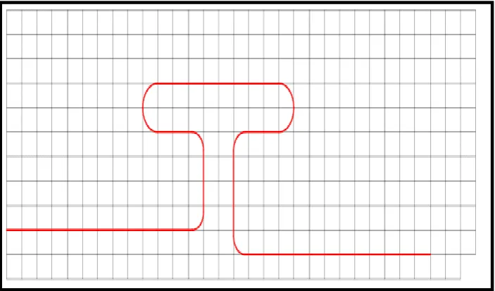
Fig 2 - Template or millimeter jig for T loop
Fig 3 - T loop placed on the jig
Fig 4 - Measuring T loop dimens ion us ing
digital caliper
Fig5 - Modeling and mes hing of T loop
(co mputer s imulation)
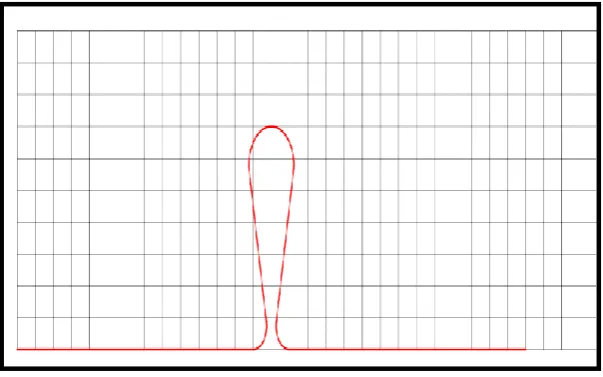
Fig 6 - Template or millimeter jig for Tear drop loop
Fig 7 - Tear drop loop placed on the jig
Fig 8 - Measuring Tear drop loop dimens ion with
digital caliper
Fig 9 - Modeling and mes hing of Tear drop loop
(co mputer s imulation)
Fig 10 - Universal tes ting machine
Fig 11 - T loop before activation
Fig 12 - Tear drop loop before activation
Fig 13 - T loop after activation
Fig 14 - 2mm activation of T loop in finite
Fig 15 - Tear drop loop after activation
Fig 16 - 2mm activation of Tear drop loop in finite
ele ment analys is
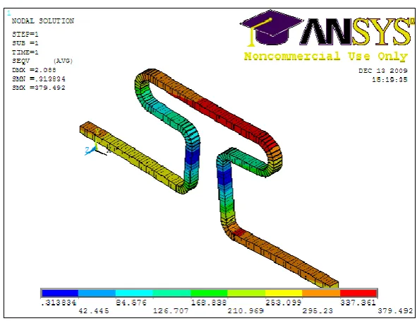
Fig 17 - Vonmises stress during 2 mm activation of
T loop in finite ele ment analys is
Fig 18 - Vonmises stress during 2 mm activation of
Introduction
INTRODUCTION
Orthodontic bio mechanics invo lves controlled
application of mo ments and forces to bring about des ired
tooth move ment and favourable tiss ue response. To
understand the forces and mo ments generated on the teeth
and s urrounding tiss ues in respo nse to applied load, severa l
experiments were carried out.
The major goals of these experimental testing
methods were mainly to predict the optimal force levels that
can be applied to the teeth and supporting structures.
Among the various in vitro models created to s imulate the
complex oral environment, finite element analys is used in
recent past is t he near accurate model to analys e the
structural s tress /strain relations hip of the teeth and
surrounding structures in response to the force applied. This
method is based on the separation of the analys is s hape into
sub domains through finite elements. This separation allows
a point analys is of the phys ical behaviour of the object
Introduction
In fixed orthodontic mechanotherapy, with adve nt o f
new orthodontic arch wires, various types of loops were
used for space clos ure. While selecting a loop for
orthodontic space clos ure, a great deal of attention must be
paid in ter ms of the individual clinical problem and
anato mical constrains. The co mmon variables that are
analysed in selecting loop mechanotherapy include the loop
des ign, its quantity of activation, wire thickness, the meta l
alloy used, type of movement des ired and the a mount of
force. When choos ing loops for clos ing spaces, it is of
utmos t importance for the professional to deter mine
precisely the force s ys tems generated, the magnitude of the
forces and the mo ments released when these loops are
activated.
Among the various arch wire materials used to
construct loops, beta titanium is the best material of choice.
β - Titanium wires have improved values of spring back
which markedly increases their working range for toot h
move ment. For a given cross section, it can be deflected
Introduction
per manent defor mation. The hig h formability of β -titaniu m
allows the fabrication of clos ing loops with or without
helices.
In this study, ‘T’ and Tear drop retraction loops of
TM A 0.017 x 0.025 inch rectangular wire were used. Tear
drop loops are s imple in des ign with better complianc e and
flexible making this loop to be mos t widely us ed for space
clos ing in both arches. T loop by itself will have a
relatively low load-deflection rate and a large maximu m
spring back. Anchorage can be control led by varying the
location of loop pos ition. The large inter attachment
distance between the auxiliary tube on the first molar and
the vertical tube of the canine allows sufficient roo m for
the large activations required. Small errors in the s hape or
geometry of the loop will not radically change the forces.
The purpose of this study was to evaluate the
computer s imulation and compare it with that of mechanica l
testing to predict the force obtained from activation of ‘T’
loops and Tear drop loo ps. ‘T’ loop and Tear drop loop
Introduction
and force were analysed. The Teardrop and ‘T’ loops were
als o manually made and force analysed with universal
testing machine. The res ults obtained in both the groups
Aims and Objectives
AIMS AND OBJECTIVES
The aim of this study is to evaluate the force obtained
from activation of ‘T’ loop and Tear drop loop by
mechanical testing method and to compare it with force
obtained from activation of ‘T’ loop and Tear drop loop by
Finite Ele ment Analys is.
The objectives of the study are:
1. To measure the force exerted by 25‘T’ loops at
various levels of activation by mechanical testing
method.
2. To meas ure the force exerted by 25 Tear drop loops at
various levels of activation by mechanical testing
method.
3. To meas ure the force exerted by computer s imulated
‘T’ loop at various levels of activation using Finite
Ele ment Analys is.
4. To meas ure the force exerted by computer s imulated
Tear drop loop at various levels of activation us ing
Aims and Objectives
5. To co mpare and analys e the force values obtained
from mechanical testing method and Finite Ele ment
Analysis for ‘T’ loops
6. To co mpare and analyse the force values obtained
from mechanical testing method and Finite Ele ment
Review of Literature
REVIEW OF LITERATURE
BIOMECHANICS
Schwarz5 8 (1932) detailed the tissue response to the
magnitude of the applied force with the capillary bed blood
press ure. He concluded that the force delivered as part of
orthodontic treatment s hould not exceed the ca pillary bed
blood press ure (20 -26g/c m2 of root s urface).
Reitan5 1 (1957) s tated that the force exerted in a tipping
move ment perfor med with continuous forces will create
compressed, cell-free areas in the periodontal membrane
more frequently than in a bo dily mo ve ment, because of the
mechanical principles involved. The appropriate a mount of
force to be applied may vary cons iderably according to the
type of movement required. For example approximately
250 gra ms of force are required during the final stage s of a
continuous bodily move ment of canines, whereas only 25
Review of Literature
B urstone1 0 (1966) stated that, as an orthodontic appliance
is activated, the operator has control over three variables
which can dete r mine the s uccess of clinician‟s adjus tment.
They are the mo ment to force ratio, the magnitude o f
mo ment or force used, and the constancy of force or
mo ment. He concluded that the segmented mechanis m have
been des igned to control tooth movement which has k now n
mo ment to force ratio and to aim an optimal biological
response by delivery of relatively constant force at a n
optimal magnitude.
Weins tein6 3 (1967) explained the efficiency of light forces
that is, force of s mall magnitude in orthodontics. He
suggested this by analys ing certain areas of the oral
musculature and their influence on tooth pos ition. He
concluded that there seems to be a genetic factor involved
in both the resting force and the stiffness of cheek
musculature in males. Masticatory forces produce a bucca l
tipping tendency on the lower premolar and contribute to
Review of Literature
Smith and B urstone9 (1984) explained about the bas ic
relations hips between force and tooth move ment and their
potential for clinical relevance. Forces produce trans lation
(bodily move ment), rotation, or a combination of
trans lation and rotation, depending upon the relations hip o f
the line of action of the force to the center of res istance o f
the tooth. Since most forces are applied at the bracket , it is
necessary to compute equivalent force sys tems at the center
of res is tance in order to predict tooth move ment.
Robert. Quinn, Ken Yos hikawa5 5 (1985) stated that the
force s yste ms developed by an ideal arch cannot be used
directly to estimate tooth move ment. They s hould first be
trans ferred to the centre of res is tance of the teeth and the
force s ystems at the centre of res istance may differ
significantly from the force sys tems at the brackets. The
relations hip between the force magnitude delivered b y
orthodontic appliances and the rate of orthodontic toot h
move ment is controvers ial. He concluded that appliances
Review of Literature
mo ment/force ratios allow the clinician to take advantage
of the type of tooth move men t proposed.
Birte Melsen, Giorgio Fiorelli. et al 3(1994), developed a
computer program that can help to des ign the optimal
orthodontic appliance. It involves several phases :
1. Identification of the required tooth move ment and its
center of rotation.
2. Deter mination of the force s yste m needed to produce
this movement.
3. Appliance des ign.
With statically indeterminate force s yste ms,
calculators are included in the progra m for co mplicated
calculations to deter mine forces based on the formulae
given by Burstone and Koenig and are available for all
poss ible wire selections.
Halazonetis1 4 (1998) studied the forces and mo ments
produced by a straight portion of an arch wire which were
Review of Literature
The purpose was to co mpare the force s yste m at the
brackets to the force s yste m at the center of res istance and
to assess whether bracket geometry can be applied to
predict initial tooth move ment. The res ults show that the
force sys tem at the center of res is tance may be of an
entirely different “geometry” type than that at the bracket.
Factors that influence the force s ystem include the
interbracket distance, the angulation of the teeth, the lengt h
of the tooth root, and the width of the bracket.
Yijin Ren, DDS, MSca; Jaap C. Maltha6 6 (2003) did a
study about the meta -analys is of the literature concerning
the optimal force or range of forces for orthodontic toot h
move ment. Articles on animal experiments were in the
majority. Bes ides variation in s pecies, there was also a
wide range of variation in force magnitudes, teeth under
study, directions of tooth move ment, duration of
experimental period, and force reactivation. Further more,
hardly any experiments were reported that provide
infor mation on the relation between the velocity of tooth
Review of Literature
from human research on the efficiency of orthodontic toot h
move ment appeared to be very limit ed. The large variation
in data fro m current literature made it imposs ible to
perfor m a meta-analys is. They had concluded that no
evidence about the optimal force level in orthodontics
could be extracted fro m literature. Well -controlled clinical
studies and more standardized animal experiments in the
orthodontic field were required to provide more ins ig ht into
the relation between the applied force and the rate of tooth
Review of Literature
RETRACTI ON LOOPS
B urrstone C.J7 (1961), stated that the most cons tant force
at optimal level are derived fro m spring possess ing low
deflection rate and high availa ble working loads. His stud y
concluded that Stainless steel have s lightly higher
maximum load than gold springs of identical rates.
B urstone and A. Jon Goldberg8 (1980) reviewed the gold
-based, stainless steel, chro me -cobalt-nickel, and nitino l
alloys, as well as beta titanium, a new material for
orthodontics. Mechanical properties and manipulative
characteris tics are s ummarized to develop a bas is for the
selection of the proper alloy for a given clinical s ituation.
Beta titanium offers an improve ment in t he properties of
presently des igned orthodontic appliances with its
increased spring back, reduced force magnitudes, good
ductility, and weldability, and also its excellent balance of
properties s hould per mit the des ign of future appliances
which deliver s uperior force s ys tems with s implified
Review of Literature
Scott R. Drake et al5 9 (1982) the mechanical properties of
three s izes of s tainless steel (SS), nickel -titanium (NT), and
titanium- mo lybdenum (TM ) orthodontic wires were studied
in tens ion, bending, and tors ion. The wires (0.016 inch,
0.017 by 0.025 inch, and 0.019 by 0.025 inch) were tes ted
in the as -received condition. The s tudy concluded that a
titanium- mo lybdenum teardrop clos ing loop delivers less
than one half of the force co mpared to stainless ste el loop
for similar activations.
B urstone6 (1982) s tudied the clinical application o f
frictionless attraction springs us ing the segmented arch
technique . He concluded the mos t important cons iderations
in the clinical use of attraction springs are the amo unt o f
distal activation, the angulation differential between the
anterior and posterior teeth, and the centricity or
eccentricity of the loop. Loop design lead to a more
efficient, hygienic, and comfortable mechanis m for space
Review of Literature
Poul Gjessing4 5 (1985) introduced new canine retraction
spring in orthodontics .On the bas is of a series o f
theoretical cons iderations described in the present report, a
canine -retraction spring was cons tructed from 0. 016 ´ 0.022
inch stainless steel wire, the principa l ele ment being a
double ovoid loop 10 mm in height . A "sweep" bend was
incorporated to avoid unwanted s ide effects at the second
pre molar. He concluded that load deflection and
mo ment/force curves were derived experimentally and
demons trated the ability o f the spring to generate and
maintain bio mechanical conditions necessary .
Faulkner et al3 3 (1989) studied the effects of severa l
parameters on the force/moment systems produced by „T‟
-loop retraction s prings. The springs are studied by us ing
the finit e element method and by experimentally meas uring
the forces and mo ments fro m the various des igns. The
res ults s howed that varying the spring height can produce
larger mo ment to force ratios as the height increases.
Changes in the pre activation bends resul t in as ymmetric
Review of Literature
intrus ive/extrus ive forces. The addition of helices at the
bends did little to alter the springs ' mechanica l
characteris tics.
S.J.Chaconas5 7 (1989) studied three contraction arch wires
na mely double delta spring, contraction torquing arch, and
contraction torquing utility arch wire. The activations
studied were intrus ion, retraction and torque. He s tated that
if deepening of the bite is indicated, the clinician s hould
use the double delta arch wire which would produce a
lingual crown tipping and poss ibly extrus ion of the incis ors
during retraction. However, if a deep overbite exists prior
to anterior tooth consolidation, the contraction torquing or
contraction torquing utility arch wires should be used s ince
they were s hown to produce the mos t effective lingual root
torquing during incis or retraction. This action would not
res ult in deepening of the bite.
T homas R. Katona et al6 2 (1989) review article describes
the mechanical properties and cl inical applications of
-Review of Literature
titanium, and multi stranded wires . Stainless steel wires
have re mained popular s ince their introduction to
orthodontics because of their forma bility, bioco mpatibility
and envir onmental stability, stiffness, resilience, and low
cost. Cobalt-chromium (C o---C r) wires can be manipulated
in a softened state and then s ubjected to heat treat ment.
Heat treat ment of C o ---C r wires results in a wire with
properties s imilar to those of stai nless steel. He found
Nitinol wires have a good s pring back and low stiffness.
This alloy, however, has poor for mability and weldability.
Beta-titanium wires provide a combination of adequate
spring back, average stiffness, good formability, and can be
welded to auxiliaries.
Fortschr Kieferorthop. B ourauel C 1 8 (1994) , based on
the favourable res ults achieved by the application o f
pseudoelastic „T‟ loops in the course of canine retraction,
investigated their application to the retra ction of maxillary
incisors. A modified Burstone „T‟ loop was made of a
pseudoelastic orthodontic nickel titanium wire and the n
Review of Literature
of the pseudoelastic spring was perfor med us ing an
individualized re traction arch enclos ing the whole front
segment. His study concluded that the location of the center
of res istance of the upper incisors has not been co mpletely
clarified. It is thus reco mmended that this matter s hould be
given further study.
D. W. Raboud, MSc, et al 1 2 (1997) studied the clinical
importance of the three -dimens ional effects of the force
syste ms s upplied by appliance des igns used for retraction .
His study concluded that the proposed numerical method
can accurately determine the force syst e ms res ulting from
this out -of-plane pre activation as well as the in -plane force
syste ms.
J. Halazonetis, DDS, MS et al1 5 (1997) tested the accuracy
of the computer s imulation, various loops that have bee n
evaluated experimentally in the literature were s imulated
and their res ponse were compared with the res ults reported
previous ly. In most cases, the res ults predicted by the
Review of Literature
values. Res ults obtained with wire specimens in an
experimental apparatus t hat meas ures forces and moments,
and values obtained from a computer s imulation, bot h
contain potential errors and can be different fro m the
values that can be expected in the clinical setting.
Development of the program is expected to address some o f
these proble ms and increase the validity of the s imulation.
Andrew J. Kuhlberg1. (1997) studied the effect of off
-center pos itioning on the force sys tem produced b y
segmented 0. 017 ´× 0.025 -inch TM A „T‟ -loops. A „T‟ -loop
was des igned to produce equal and o ppos ite mo ments in the
centered pos ition. The spring was tested in seven pos itions,
centered, 1, 2, and 3 mm toward the anterior attachment,
and 1, 2, and 3 mm toward the posterior attachments. The
horizontal force, vertical force, and alpha and beta
mo ments were meas ured over 6 mm of spring activation.
The res ults s howed that the alpha/beta mo ment ratio was
dependent only on the spring pos ition, and independent o f
Review of Literature
effectively produces a cons is tent moment differentia l
through the range of spring activation.
Demetrios J. Halazonetis1 6, (1998) stated that Control o f
the force s ys tem that is applied to teeth is one of the main
proble ms in the field of biomechanics. A major use of loops
is in the ret raction of canines, where a correct mo ment to
force ratio is essential for bodily mo ve ment. The des ign of
the loop influences both the force levels and the mo ment to
force ratio (M /F) in s uch a way that it is difficult to change
the one without adversely affecting the other.
Marcelo do Amaral Ferreira3 5,(1999) studied the
mechanical behaviour of orthodontics clos ing loops, wit h
three different wire materials (stainless steel, cobalt
-chro mium and titanium- molybdenum) and with different
cross-sections and a double delta des ign in tens ion tes ts. It
was hypothes ized that loads, after spring activation, and
spring rate, are dependent on cross -section, wire material,
and activation. The res ults s howed that the loads are
Review of Literature
Titanium- molybdenum 0. 017 × 0. 025 inch (Ormco) springs
showed the s mallest loads and the bes t spring rate.
(b = 84.9 g/mm) .
Jie Chen et al2 8 (2000) studied the e ffects of T-Loop
Geometry on Its Forces and M oments and de mons trated that
the mo ments and forces generated by a T -loop spring are
functions of its geometry and gable angle co mbined with
heat treat ment. This Study concluded that increas ing its
vertical or horizontal dimens ion reduces the load -deflectio n
rate and the moment -to-force ratio. Gable preactivation and
stress relieving heat treatment have the oppos ite effect.
Kwangchul Choy3 1 (2002), made a study on C ontrolled
Space C los ure with a Statically Deter minate R etraction
Syste m. SDRS uses frictionless mechanics, an d
its statically determinate force delivery s ys te m
(i.e, magnitude, direction, and point of force application)
can be eas ily establis hed by a s ingle force meas ure ment. He
stated that the cantilever spring has a low load-deflection
Review of Literature
reactivation is often not required. The force direction
changes minimally and re mains during s pace clos ure, as
does the axis of rotation. Therefore, unnecessary jiggling o f
teeth can be minimized.
Andrew J. Kuhlberg et al2 (2003) study was to compare
meas ured tooth movements with the theoretical force
syste m exerted by differential moment clos ing loops.
Tloop springs des igned to deliver a differential mo ment
-to-force ratio to the posterior Vs the anterior teeth were
used. The anterior teeth, as repres ented by the canines,
were retracted an average of 1. 73 mm, whereas the
posterior anchorage (molars) moved mes ially only 0.50
mm. Furthermore, the canine teeth exhibited tipping or
trans lation, and the molars s howed mesial root move ment.
Kum M , Quick A et al3 0 (2004) investigated the loads
("forces "), mo ments and mo ment:force ratios (M/F)
generated during activation and deactivation of three
clos ing loop des igns constructed from two different
Review of Literature
M/F ratios for trans lation are not poss ible with non -pre
activated vertical „U‟-Loops or symmetrical „T‟-Loops.
T hiesen G et al6 1 (2005) did a s tudy to determine the
mechanical characteristics of beta -titanium „ T‟ -loops w ith
and without helices, with 0 and 180 degree gable bends,
constructed from 0.017 inch x 0.025 inch and 0.019 inch x
0.025 inch wire. The horizontal forces and mo ment/force
ratios generated by plain „T‟ -loops with 180 degree gable
bends yielded more adequate force sys tems. He concluded
incorporation of helices in the design of „T‟ -loops seems to
be unnecessary.
Renato Parsekian Martinsa 5 3; (2008) stated that both
curvature and bend pre activated „T‟ loop produced
symmetrical mo ments with s mall vertical force. The
curvature pre activated „T‟ loops produced horizontal
forces that were lighter than the bend pre activated „T‟
loops. The curvature pre activated „T‟ loops produced MF
ratios that were approximately 2.5 mm higher than the bend
Review of Literature
activated T loops s howed less force decay per 0.5 mm of
deactivation (29.8 gf) than the bend pre activated „T‟ loops.
Poowadon Kos on-ittikul et al4 4 (2008) s tated that the
LDR (low deflection rate) for one clos ing loo p s hould be as
low as poss ible so that the force applied to the tooth will be
low to minimize pathological effects on the periodonta l
support and also maintain constant force over a large
deflection range. According to the tests, the helical loop
with reversed ar ms provided the lowest LDR among the
four s imple clos ing loops des igns studied. Wire bending to
change the s hape and configurations of the loop is the one
procedure to improve or change the force/deflectio n
properties of the orthodontics wire mater ial. The major
effect of the LDR co mes from the amount of the wire
incorporated into a clos ing loop.
Miceli Beck Guimaraes Blaya et4 1 (2009) analyzed the
mechanical behaviour of different orthodontic retractio n
loops. Two des igns of orthodontic loops for clos ing space
Review of Literature
loop (C), of two different heights (6 and 8 mm), and two
types of orthodontic wires (s tainless steel – 0.19‟ × 0.25‟;
TM A – titanium mo lybdenum alloy – 0.016‟ × 0.016‟). The
group “teardrop -8 mm-TM A” together with the group
“circle-8 mm-TMA” presented the lowest mean value,
differing statistically from all of the other groups. It was
concluded that the alloy of the wire and the height of the
Review of Literature
FINITE ELEMENT ANALYSI S
Osamu Miyakawa et al4 3 (1985) described a new
simulation method to analyze the initial behaviour of the
total s ys tem co mpris ing orthodontic appliance, teeth, and
their s upporting s tructures. It is bas ed on a finite ele ment
method which additionally takes account of a rotationa l
degree of freedo m. Bea m and rod ele ments are used for
finite ele ment idealization of orthodontic appliance.
Through spring ele ments it is connected with the teeth
supported by the alveolar structures. The technique of
„initial strain‟ is introduced so as to analyze the effects of a
gable bend and activation on the force s yste m which is
delivered by the orthodontic appliance. As co mpared with
the photo elastic technique hitherto used, this method
serves to investigate s yste matically and quantitatively the
initial aspect of orthodontic tooth movement.
Raymond E. Siatkows ki at al4 9 (1997) introduced new
clos ing loop us ing FEM (ANSYS soft ware -Swanson
Review of Literature
capable of delivering a non varying target M/F within the
range of 8.0 -9.1 mm inherently, without adding res idual
mo ments by twist or bends (commo nly gable bends )
anywhere in the arch wire or loop before insertion. The
res ulting precise fo rce s ystems delivered with non varying
M/F can move groups of teeth more accurately to achieve
predeter mined anteroposterior treatment goals for esthetics
and/or stability. The experimental res ults s how that the
loops must be bent accurately to achieve the ir des ign
potential. The negative impact on M/F of various
dimens ional changes to the loop design is presented.
Experimental data is presented illus trating the improved
perfor mance of the new des ign over s tandard available
des igns. Suggested applications o f the des ign for varyin g
anchorage require ments are presented, along with a cas e
report in which rigorous protraction require ments were met.
Young –ll Chang et al 6 6(2004), compared the effects of a
multi loop edgewise archwire (M EAW) on dis tal en masse
move ment with a continuous plain ideal archwire(IA) us ing
Review of Literature
models of the maxillary dentition was cons tructed
according to Wheeler and aligned with reference to the
facial axis point of Andrews and als o standard edgewis e
bracket and stainless steel IA and MEAW. The stress
distribution and displacement of the maxillary dentition
were analyzed when classII inter maxillary elas tics
(300gm/s ide) were applied. The results s howed that the
MEAW produced low amo unt of tooth displacement.
Individual tooth move ment was more uniform and balanced
and less vertical displacement was seen with M EAW.
Rodrigo F. Viecilli et al5 6(2006) studied about
Self-corrective „T‟ -loop design for differential space closure
.The effects of steps, angles, and vertical forces were
combined to produce an ideal „T‟ -loop des ign that would
provide a more deter minate force sys tem. The effects and
force s yste ms are estimated based on s implified locations
of the centers of res istance, ass uming relatively constant
behavior of the centers of rotation. These s implifications
might differ s lightly fro m what happens in vivo. The s tud y
Review of Literature
spring tester capable of reproducing the geo metric
corrections s hould be used to ens ure a precise force s ys tem.
Mohd. Reza safavi4 2 (2006) studied M/F ratio of four
different clos ing loops us ing FEM. The objective of the
study was to co mpare the forces, mo ments and
mo ment/force (M /F) ratios of the opus loop, „L‟ –loop,
„T‟–loop and vertical helical closing loop (VHC loop) in a
segmented arch with the finite element method (FEM).
Results s howed that the highest horizontal and vertical
forces were produced by the „ L‟–loop (with and without pre
activation bends) and in most cases the lowest forces were
produced by the VHC loop. He concluded Loops with pre
activation bends produced marked changes in the M /F ratio
and loops without pre activation bends low, but relat ively
constant, M/F ratios over the full range of activation.
Maria Elisa Rodrigues Coimbra3 8 et al (2008), studied
about Mechanical tes ting and Finite ele ment analys is o f
orthodontic teardrop loop. The purpose of this study was to
Review of Literature
and the tors ion obtained after the activation of teardrop
loops of 3 heights. The co mputer simulation accurately
predicted the experimentally deter mined mechanical
behaviour of teardrop loops of different heights and s hould
be cons idered an alternative for des igning orthodontic
Materials and Methods
MATERIALS AND METHODS
The present study was conducted to evaluate and
compare the force obtained after activation of Tear drop
and “T” loops by mechanical method and by finite element
method (Co mputer s imulation). Retraction loops of TM A
0.17x 0.25inch rectangular wire were used.
The testing apparatus cons is ted of co mputer with
ANSYS software and universal testing machine (S H IM ADZ U
Model;AG -IS 50 KN) (Fig 10 )
Fifty clos ing loops made of TM A 0. 017 × 0.025 -inch
rectangular wires were bent. Based on the d es ign of the
loops, they were divided into 2 groups na mely 25 Tear drop
loops4 0 (Fig 7) and 25 T loops (Fig 3 ). Dimens ion of Tear
drop loop was 7 mm height and 2.5mm internal arch
circumference. Geometry of T loop was 5mm anterior (α)
vertical height and 4 mm posterior (β) vertical height.
Posterior vertical height was made to be in level wit h
Materials and Methods
10mm. The sa me operator prepared the specimens us ing a
template or millimetre jig4 1.
A light wire plier with TC tip (Dentronix, US A) and
Tweed loop for ming plier ( R ocky M ountain G ERMAN Y) were
used for making the loops. After preparation, each loop had
28 mm of total length of which anterior and posterior 5mm
of wire allowed its attachment to a universal tes ting
ma chine (Fig 10 ). Remaining 18mm represented the
standard inter bracket dis tance (IBD)2 and loops were
placed centrally 3 6 .A D igital Vernier Caliper (fig 1) was
used to check the dimens ions of the loops to main tain a
standard dimens ion (fig 4&8 .) Pre activation bends were
not given in any loop s.
MATERIALS
1. 0.017× 0.025 TM A (Omrco, Glendora,C A ) straight
wire (Fig 1).
2. Orthodontic light arch plier with TC tip (Dentronix,
USA) (Fig 1).
3. Tweed loop for ming plier ( Rocky M ountain GERM AN Y)
Materials and Methods
4. Orthodontic arc h wire cutter (heavy duty) (Fig 1).
5. Template or millimeter jig (Fig 2&6 ). Template
prepared with a help of Solid Works software 2005
(DWG -Editor).
6. Digital Vernier Caliper (M itutoya, Japan) (Fig 1).
7. A Personal computer with the following configuration
was used:
Monitor -- IBM TFT M onitor
CPU -- IBM (Intellis tation Z Pro)
Processor -- Intel Xeon (Dual Processor)
Memory Capacity -- Primary -2 GB, Secondary –
80 GB
Graphics card -- ATI FireGL V 71
Software -- ANSYS (vers ion 11,)
Operative s ys tem -- Windows vista
METHODOL OGY:
Evaluation with Universal testing machine.
The s prings were then s ubjected to a tens ile load on
the universal testing machine. (S HI MAD Z U model: AG-IS
Materials and Methods
purpose, one end of the specimen was fixed to the machine,
and the other end was displaced. The loops were s ubjected
to activation s teps with increments of 0.5 mm at a rate of
1.0 mm per minute up to a maximum displace ment of 2mm.
The forces were meas ured and recorded.
Evaluation using Computer simulation:
The geo metry of the s prings used in the computer
simulation was obtained with the help of jig dimen s ion. The
Tear drop loop (Fig 9) and „T‟ loop models (Fig 5 ) were
created in ANSYS software accordi ng to the characteristics
of the loop structures and also cons idering the s pecific
move ments imposed by the intended mechanical activation.
BEAM 4 ele ments were used for cons tructing loop models
for analys is3 6. This (finite) uni axial element could respond
to tens ion, compress ion, traction, and tors ion move ments.
The BEAM 4 element has 6 degree of freedo m,
3 trans lation and 3 rotation points around the axis3 6.The
modulus of elas ticity of the orthodontic wire used in the
Materials and Methods
coefficient of 0.130 (Siatkows ki,AJO 1997)4 8. Both the
Tear drop loop and the „T‟ loop models were discretized
into finite elements, and an average of 237 ele ments were
used for modelling. To s imulate the activation s i milar to
universal testing machine, the boundary conditions were
defined so that the terminal node in the alpha segment
(anterior) was restrained (i.e. it was not able to move in the
X, Y or Z axes, and it was not able to rotate around these
axes )4 1 , 3 6. The terminal node of the beta segment (posterior)
was restrained in a s imilar way to the alpha segment,
except that it was free to move along the horizontal leg of
the posterior segment. This movement s imulated the wire
sliding distally through a molar tube. Force exerted on the
horizontal axis during every 0.5mm incre mental activation
of the loop was deter mined up to a maximum of 2 mm
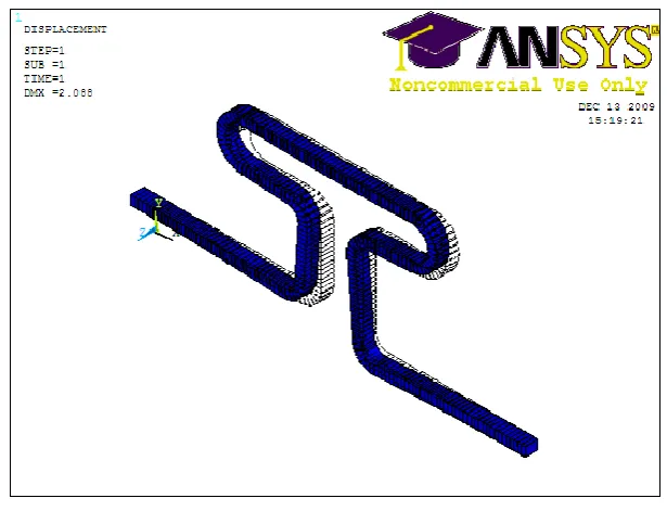
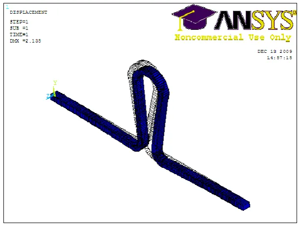
activation (Fig 14 & 15 ). Both the Tear drop loop mode l
and the „T‟ loop model were subjected to this simulated
activation and the forces exerted by these loops were
FIG 1- ARMAMENTARIUM
[image:46.595.123.475.543.749.2]
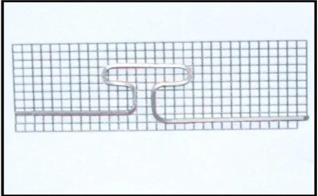
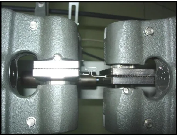
FIG 3- T LOOP PLACED ON THE JIG MANUALLY MADE
[image:47.595.162.437.470.677.2]
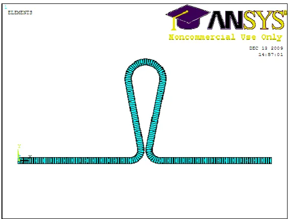
FIG 5 - MODELING AND MESHING OF T LOOP (COMPUTER SIMULATION)
FIG 6- TEMPLATE OR MILLIMETER JIG FOR TEAR DROP LOOP
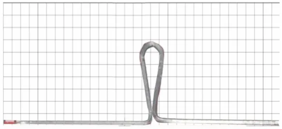
[image:48.595.148.450.525.713.2]FIG 7- TEAR DROP LOOP PLACED ON THE JIG MANUALLY MADE
[image:49.595.161.437.435.640.2]
FIG 8 - MEASURING TEAR DROP LOOP DIMENSION WITH DIGITAL CALIPER
FIG 10 - UNIVERSAL TESTING MACHINE
[image:50.595.194.405.416.693.2]FIG 12 - TEAR DROP LOOP BEFORE ACTIVATION
[image:51.595.152.445.460.684.2]FIG 14 - 2MM ACTIVATION OF T LOOP (COMPUTER SIMULATION)
[image:52.595.168.476.460.695.2]
FIG 16 - 2MM ACTIVATION OF TEAR DROP LOOP (COMPUTER SIMULATION)
[image:53.595.143.450.437.669.2]FIG 18- VONMISES STRESS DURING 2MM ACTIVATION OF TEAR DROP LOOP
Results
RESULTS
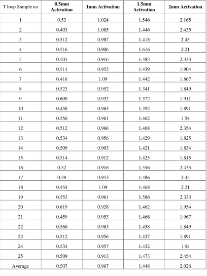
1. Force value at various levels of activation (from 0.5 mm
to 2 mm) for ‘T’ loop and Tear drop loop of the 25
samples each were obtained fro m mechanical testing.
The res ults are presented in Table 1 and 2 respectively.
2. Computer s imulated force val ue of ‘T’ loop and Tear
drop loop were obtained and presented in Table 3 and 4
respectively.
3. Unpaired ‘t’ test showed statistically significant
difference between T loop and Tear drop loop force
values. The data is presented in table 5.
4. Paired ‘t’ test analysis for computer simulation and
experimental testing of ‘T’ loop and Tear drop loop were
Results
[image:56.595.108.529.201.760.2]TABLES
Table 1. Force values obtained from T loops at various
levels of activation in universal testing machine (Newton).
T loop Sample no 0.5mm
Activation 1mm Activation
1.5mm
Activation 2mm Activation
1 0.53 1.024 1.546 2.165
2 0.403 1.085 1.446 2.435
3 0.512 0.987 1.418 2.45
4 0.516 0.906 1.616 2.21
5 0.501 0.916 1.483 2.333
6 0.511 0.953 1.439 1.904
7 0.416 1.09 1.442 1.867
8 0.523 0.952 1.341 1.849
9 0.609 0.932 1.372 1.911
10 0.458 0.963 1.392 1.891
11 0.556 0.961 1.462 1.54
12 0.512 0.966 1.468 2.354
13 0.534 0.956 1.429 1.825
14 0.509 0.903 1.421 1.834
15 0.514 0.912 1.425 1.815
16 0.52 0.916 1.556 2.435
17 0.59 0.953 1.486 2.45
18 0.454 1.09 1.468 2.21
19 0.553 0.961 1.586 2.333
20 0.619 0.928 1.462 1.954
21 0.459 0.953 1.466 1.967
22 0.566 0.963 1.458 1.849
23 0.512 0.956 1.437 1.891
24 0.534 0.957 1.432 1.54
25 0.509 0.913 1.473 2.454
Results
Table 2. Force values obtained from Tear drop loops at various
levels of activation in universal testing machine (Newton).
0.5 1 1.5 2
1 0.995 1.76 2.78 3.24
2 0.831 1.47 1.92 3.6
3 0.841 1.545 2.359 3.227
4 0.842 1.86 2.743 3.515
5 0.825 2.08 2.99 3.49
6 0.805 1.77 2.12 3.306
7 0.902 1.436 1.859 3.617
8 0.934 1.352 2.001 3.054
9 0.801 1.647 2.125 3.232
10 0.729 1.551 2.75 3.251
11 0.847 1.391 2.05 3.598
12 0.742 1.669 2.078 3.263
13 0.745 1.496 2.161 3.004
14 0.732 1.379 2.005 3.058
15 0.807 1.352 1.974 3.021
16 0.835 1.536 2.752 3.543
17 0.835 1.353 2.152 3.317
18 0.85 1.648 2.118 3.582
19 0.827 1.553 2.151 3.091
20 0.815 1.431 2.015 3.242
21 0.892 1.659 1.963 3.241
22 0.934 1.486 2.121 3.599
23 0.728 1.369 1.959 3.252
24 0.837 1.472 2.091 3.015
25 0.741 1.535 2.152 3.148
Results
Table 3. Descriptive statis tics for the force level (in N)
related during varying activation levels for ‘T’ loop
Table 4. Descriptive statis tics for the force level (in N)
related during varying activation levels for Tear drop loop.
Activation
(mm) Mean(N) Maximum(N) Minimum(N) SD
0.5 0.827 0.995 0.728 0.068
1.0 1.584 2.08 1.352 0.208
1.5 2.261 2.08 1.859 0.342
2.0 3.298 3.617 3.004 0.322
Activation(mm) Mean (N) Maximum(N) Minimum(N) SD
0.5 0.507 0.619 0.403 0.05
1.0 0.967 1.09 0.903 0.053
1.5 1.448 1.616 1.341 0.06
[image:58.595.103.513.548.712.2]Results
Table 5. Co mputer s imulation res ults for T loop
Activation ( mm) Force in Fx (N)
0.5 0.481
1.0 0.960
1.5 1.4416
2.0 1.920
x- Force in hor izontal axis, N - Newton,
Table 6. Co mputer s imulation res ults for Tear drop loop
Activation (mm) Force in Fx (N)
0.5 0.809
1.0 1.618
1.5 2.427
2.0 3.236
[image:59.595.168.444.510.676.2]Results
Table 7. Tear Drop and T Loop Unpaired Students T test
0.5mm activation
Loop Mean SD P
T loop Teardrop loop 0.5168 0.826 0.05193 0.06893 ˂ 0.001
1mm activation
Loop Mean SD P
T loop Teardrop loop
0.96384 1.552
0.05422
0.17866 ˂ 0.001
1.5mm activation
Loop Mean SD P
T loop
Teardrop loop
1.460
2.245
0.060
0.0318 ˂ 0.001
2mm activation
Loop Mean SD P
T loop
Teardrop loop
2.05
3.300
0.28
0.20 ˂ 0.001
Results
Table 8. Paired ‘t’ test for T loop between co mputer
stimulation and experiment.
Activation
(mm)
Experimental valve
for T loops (N)
Computer
simulation value(N)
0.5 0.507 0.48
1.0 0.967 0.96
1.5 1.448 1.44
2.0 2.026 1.92
P value = 0.1915 (not statis tically significant.)
Table9. Paired ‘t’ test for Tear drop loop between
computer stimulation and experiment.
Activation
( mm)
Experimental value
for Tear drop
loops(N)
Computer
simulation value
(N)
0.5 0.827 0.809
1.0 1.584 1.618
1.5 2.261 2.426
2.0 3.298 3.236
Results
GRAPHS
Graph- 1: F orce obtained on activation of T ear drop
loop to 2mm in univers al tes ting machine
0 330
30 60 90 120 150 180 210 240 270 300
F
o
rc
e
(g
f)
0 0.3 0.6 0.9 1.2 1.5 1.8 2.1 2.5
Stroke(mm)
Max
Results
Graph – 2: F orce obtained on activation of
T loop to 2mm in universal tes ting machine
0 210 20 40 60 80 100 120 140 160 180 200 F o rc e (g f)
0 0.3 0.6 0.9 1.2 1.5 1.8 2.1 2.5
Stroke(mm)
Max
Sample: 8
Results
Graph- 3: Mean f orce tendency (n) for T loops and tear
drop loops (mechanical tes ting)
Graph-4: Mean force tendency (n) for T loops and tear
Discussion
DISCUSSION
Biomechanics is the study and analysis of mechanica l
function in living bodies and the effect of the force on the
form and motion of living bodies. Forces are load or
external influences applied to a body that changes or tends
to change the pos ition of that body. If a force is applied to
the center of the res istance the whole body moves equally
in the direction of force applied. When orthodontic forces
are applied and when the line of the force does not pass
through the center of the res istanc e a moment is created.
In orthodontic mechanotherapy, several orthodontic
mechanis ms were des igned for clos ing loops. Among the
various devices described there are many ranges of loops,
which may be used, incorporated into continuous or
segmented arches, for vertical and saggital dental
move ment. Due to the large number of options, a great deal
of attention must be paid when selecting the mos t
Discussion
In this choice, certain variables mus t be analyzed,
among the m the loop des ign, it quantity of activation, wire
thickness, the metal alloy used, type of move ment des ired
and the quantity of force necessary. When us ing loops for
clos ing s paces, it is of the ut most importance for the
profess ional to determine precisely the s ys tem of fo rces
generated; that is, it is important for the orthodontist to
know the magnitude of Orthodontic forces a nd the mo ments
released when these devices are activated.
Orthodontic forces applied by means of orthodontic
appliances are dependent on various fac tors that determine
the s uccess of the treatment. The operator has control over
a few factors like moment: force ratio, magnitude of force
and constancy of force B urstone (1966)1 0
Optimum control of tooth move ment requires
application of specific orthodon tic force s yste ms.
Therefore, the knowledge of the mechanics of orthodontic
appliances is essential to achieve desirable and predictable
Discussion
Load deflection rate is also important for a n
orthodontic spring as its mo ment to force ratio. Force
produced per unit deflection is the load deflection rate. A
low load deflection rate is preferred for orthodontic springs
(P oowadon Kos on –ittikul et al. 2008)4 4 Low load
deflection is preferred for two reas ons : 1) it maintains a
des irab le force level in the PDL 2) It offers greater
accuracy in controlling force magnitude. Hence an ideal
orthodontic spring s hould have a greater M/F ratio and a
lower load deflection rate. (B urstone 1966)1 0
Crown tipping, trans lation and root mov e ment are
exa mples of different types of tooth movement that can be
produced with proper mo ment to force ratio (Graber,
Vanarsdall)2 2 An important aspect of orthodontic treat ment
is to unders tand tooth movement in response to mechanical
loads and the assoc iated adjacent tiss ue res ponse at bot h
clinical and histological levels (Prof fit)6 5.
To move teeth in a controlled fas hion, correct
mechanical principles and an ideal orthodontic appliance
Discussion
of malocclus ion to better align the teeth to be moved and
ease of place ment in the mouth. While the final goal of a
retraction s ys tem is efficient, effective clos ure of s pace
within the dental arch, the des igns and materials of the
appliances used to accomplis h this effect vary
cons iderably.(M.G.Faulkner et al 1991)3 3
To provide the appropriate force s ys tem, the appliance
must have the following mechanical characteris tics : 1. It
must provide appropriate levels of force and mo ment
-to-force (M /F) ratios to achieve the tooth displacement
des ired.2. It must be able to undergo a reasonable range of
activation/deactivation in which the appliance delivers
relatively cons tant forces and mo ments.3. It mus t be s mall
enough to fit comfortably in the space available for
intraoral treat ment. (M.G.Faulkner et al 1991)3 3
Number of procedures is used for retraction o f
anterior segments in treatment of extraction case. In s liding
mechanics, force diss ipates due to friction which is
Discussion
undes irable effects the retraction of anterior teeth b y
frictionless s yste m is based upon the incorporation of loop.
(Charles B urstone et al 1976)5
In frictionless mechanics, teeth are moved without the
brackets s liding along the arch wire. Retract ion is
accomplis hed with loops or springs, which offer more
controlled tooth move ment than s liding mechanics. The
force of a retraction s pring is applied by pulling the dista l
end through the molar tube and cinching it back. The
mo ment is deter mined by the wire configuration and by the
presence of pre activation or gable bends, which produce an
activation mo ment.
The addition of helices lowers the load/deflectio n
rate without s ignificantly affecting the mo ment to force
ratio (M.G.Faulkner1991)3 3. Reducing the load deflection
rates of orthodontic springs is important for it provides a
relative constancy of the mo ment - to- force ratio applied to
the teeth with concomitant , force a stable dental
Discussion
mo me nt to force ratio can be improved by increas ing its
height, horizontal length, and loop diameter of the spring.
The sa me is true of a T -loop, but once the horizonta l
section beco mes equal in length to the vertical section, no
improvement in the mo ment to force ratio is gained b y
lengthening the horizontal section. (B urstone et al 1976)5
Biomechanical cons ideration requires that arch wire
stiffness be an important criterion upon which rests the
relations hip between orthodontic forces and deflection
within the elastic working range. Stiffness is directly
related to the cross sectional s ize and s hape of the wire and
affected by bracket width, interbracket distance, the length
of the wire, wire material, hardness and the incorporatio n
of loops.
B urstone et al 19826 concluded that the most
important cons ideration in the clinical use of attraction
springs are the amount of distal activation, the angulations
differential between the anterior and posterior teeth and
Discussion
Loop des ign lead to a more efficient, hygienic, and
comfortable mechanis m for space clos ure. Principles of
loop des ign include use of a rectangular wire for preventing
the rolling of loop arch wire in the bracket s lots, use of a
simple des ign, a failsafe mechanis m and adequate range of
action to deliver continuous controlled force. (Wick
Alexander)6 4
The different biomaterials used in orthodontic wires
can be s tainless steel, nickel titanium or beta -titanium.
When for med into different configuration, they genera te
bio mechanical forces which are trans mitted to the appliance
to produced tooth move ment. The ideal arch wire s hould
deliver a low constant force, good spring back and
bioco mpatible. (Nanda)4 6 β - Titanium wires have
improved values of spring back which markedly increases
their working range for tooth movement. For a given cross
section, it can be deflected approximately twice as far as
stainless steel wire without permanent defor mation