- AN IN VITRO STUDY
Dissertation submitted to
THE TAMILNADU DR. M.G.R.MEDICAL UNIVERSITY
In partial fulfillment for the degree of
MASTER OF DENTAL SURGERY
BRANCH V
Words seem less to express my deep sense of gratitude to my postgraduate teacher Dr.
N.R. Krishnaswamy, M.D.S., M.Ortho RCS. (Edin), Diplomat of Indian board of
Orthodontics, Professor and Head, Department of Orthodontics, Ragas Dental College and
Hospital, Chennai, for his valuable guidance and suggestions, tireless pursuit for perfection,
immense and constant support, encouragement and keen surveillance for the minute details
throughout this dissertation.
I am privileged to express my extreme gratefulness to my respected Professor
Dr. S.
Venkateswaran,
M.D.S (Diplomat of Indian Board of Orthodontics)for being a constant source of
support and supervision.
I gladly utilize this opportunity to express my deep sense of gratitude and indebtedness
to my respected Professor Dr. Ashwin George,
M.D.S, (Diplomat of Indian Board of Orthodontics)for
his everlasting inspiration.
I am grateful and sincerely thankful to my guide, Dr. V. K. Shakeel Ahmed,
(Reader)for
his vehement personal interest, incessant encouragement, valuable suggestions, constructive
criticism, wise counsel and never ending willingness to render generous help to me in carrying
available in this institution in successful completion of this study.
My sincere thanks to Dr. N.S. Azhagarasan, M.D.S., (Professor and Head of the
Department of Prosthodontics) and the department staff for guidance and insight in the
technical details of using the surveyor and carrying out this dissertation.
I owe enormous debt of gratitude to Dr. Rooban. T (Professor, Dept. of Oral Pathology)
support, guidance and insight in carrying out this dissertation, as well as helping me with the
statistical analysis.
I would also like to thank Dr. Rajan, (
Lecturer,Dept. of Orthodontics) for his support
and suggestions in the experimental aspects of this study.
I am greatly beholden to Dr. Shahul
(Assosiate Professor), Dr. Anand
(Reader) ,Dr.
Jayakumar
(Reader), Dr. Rekha(
Reader), and
lecturers, Dr. Shobana, Dr. Biju, Dr. Prabhu for
My heartfelt thanks to my wonderful batch mates, Dr.Ashwin Thomas, Dr. Sreesan
N.S. , Dr. V. Saravanan, Dr. D. Mahalakshmi , Dr. S. Vinoth, Dr. Ayush Sharma , and Dr.
Sabitha Nair who were cheerfully available at all times to help me. I wish them a successful
career ahead.who were cheerfully available at all times to help me. I wish them a successful
career ahead.
I also extend my gratitude to my juniors, Dr. Manikandan, Dr. Shakthi, Dr. Siva
subramanium, Dr. Vijay, Dr. Aarthi, Dr. Ashwin, Dr. Ravanth, Dr. Deepak , Dr. Vishal, Dr.
Vikram, Dr. Gayathri, Dr. Regina, Dr. Manali, Dr. Murali, Dr. Saptharishi ,Dr. femin, for all
their support and for cooperating with me to conduct this study on their patients.
I also thank Mr. Ashok and Mr. Rajendran for helping me with the photographs for
the study.
I would like to thank Mrs. Marina, Sister Lakshmi, Sister Rathi, Sister Kanaka, Ms.
Haseena, Mr. Mani, Mr. Bhaskar, Ms. Divya & Ms. Banu for their co-operation and help
during my post-graduate course.
I would like to especially thank Dr. Rashmikumar B. Vora (my father), Mrs. Manisha R.
past, present and all my future endeavors. I thank my in laws for being patient and
understanding all through, and helping me to see the positive side of every event in life.
My wife Dr. Bhakti Vora has been my pillar of support and an eternal source of energy
in every endeavour of mine. She has been there with me through the most difficult times and
helped me complete the study as her own. Without her support and love, this course and this
study would have just been a dream.
Above all, am thankful to God almighty, to have given me the strength to pursue this
TITLE
PAGE NUMBER
1.
INTRODUCTION
1
2.
REVIEW OF LITERATURE
4
3.
MATERIALS AND METHODS
32
4.
RESULTS
37
5. DISCUSSION
43
6.
SUMMARY AND CONCLUSION 60
1
INTRODUCTION
The use of miniscrew implants (MSIs) has revolutionized the specialty of
orthodontics. MSIs are now more commonly being used in clinical practice to enhance
orthodontic anchorage. MSI have many advantages including easy placement and removal,
immediate loading, low cost and versatility to use in various clinical situations.21,88 These
benefits have led to a rapid rise in the popularity of MSI.
Numerous anatomical sites for MSI application have been presented in the maxilla
and mandible15,16,17,41,44,50,71,108,109,119 . The inter-radicular septum is considered as one of the
most commonly used locations for MSI placement when a full complement of dentition is
present. 22,75,106,143 Hence, assessment of inter-radicular distance is of utmost importance
because it relates to both safety of vital structures and stability of the MSI. Clinically, there
could be many instances in which a clinician comes across cases having reduced
inter-radicular space at the desired MSI placement site. Factors that would potentially affect the
availability of inter-radicular space are proximity of neighboring roots, root form and its
anatomy, axial inclinations of teeth due to dento-alveolar compensation in sagittal skeletal
discrepancy and ethnic variability.22,75,105,142 Because of great anatomic variations in the inter-radicular region, it is important to evaluate the anatomy of the desired location for MSI
placement and consider different diameters and lengths of MSI for each patient.76,89,62,76,140
Several studies have been performed to assess the safe locations in the inter-radicular
space for MSI placement, the so called “safe zones” to avoid root damage.41,109To determine
the ideal diameter of an MSI, few studies have assessed the availability of inter-radicular
spaces. 22,75,105,142 A minimum of 1mm of alveolar bone around the MSI has been recommended to preserve the periodontal health. Therefore, when the diameter of MSI and
minimum clearance of alveolar bone are considered, the inter-radicular space needed is 3mm
2
It might seem logical that a longer implant can provide greater mechanical retention because
of greater surface area contacting the bone4. But Park and Cho100have suggested that even a slight deviation from the ideal path can cause root damage with a longer implant.
Successful MSI placement, in both the maxillary and mandibular regions, requires
accurate angulation and position in order to achieve safety, mechanical retention and primary
stability.13,27,98,137,138 A deviation from the planned drilling axis in mesio-distal and vertical
direction can occur as most clinicians generally insert MSI’s without a guide and place it free
hand using only panoramic radiographs or periapical films to estimate the inter-radicular
space. Wu et al142 reported that MSI insertion without an accurate surgical guide results in
20% of root injuries during positioning. MSI insertion in inter-radicular areas requires
appropriate radiologic planning, including a guide for determination of a safer placement site.
In recent years, several guides were developed for MSI placement to improve the accuracy of
MSI insertion especially in anatomically difficult regions.5,22,30,38,90,91 Most of these surgical guide systems use 2-dimensional (2D) radiographs which have technical limitations for
estimating the precise placement position in the 3 dimensions of space.5,118,122,130 Hence, the two dimensional radiographic image of such guides does not necessarily reflect its true
spatial relationship with adjacent 3-dimensional anatomical structures and is inadequate in
eliminating the risk of root damage.35,60,75,80,111,120,122,130. It might be preferable to use cone beam computed tomography to assess the inter-radicular space.23.75,104In a study by Kau et
al54 to evaluated placement of MSI using cone beam computed tomography, it was found that in spite of MSI placement by experienced clinicians, on average 65.7% of the roots were in
MSI contact.
It is also considered that bone density is a key factor for the efficiency of MSI
3
sparse literature to determine the factors responsible for axial deviation of MSI immediately
after inserted. The role of bone density, various MSI lengths, various MSI diameters, inserted
methods and their effects on angular deviation of MSI is still a subject seldom discussed and
emphasized upon in literature.
Therefore the aim of this experimental artificial bone study was to evaluate the factors
4
REVIEW OF LITERATURE
Anchorage in orthodontics is the resistance to unwanted tooth movement. In the field of
orthodontics, several methods have been developed to overcome the critical problem of
anchorage. Among them, skeletal anchorage systems have gained increasing interest.
MSIs are mainly preferred among the others, because of their comparatively much smaller
size. These small dimensions allow an increase in potential intraoral placement sites, even
interdentally between the roots. Due to the small size, their placement and removal are simple
and the surgical trauma is restricted to the minimum. This means shorter chair time and less
pain and discomfort, whilst low cost and the ability of immediate loading could be considered
as additional advantages. Despite the many advantages they present, their clinical behaviour
is still unclear. The generally accepted protocol for successful and predictable placement of
MSIs includes atraumatic surgical technique, short healing period, biocompatible materials,
and patient management. An ideal method for achieving stable MSIs in the initial integration
stage has not yet been developed. Risk factors that can jeopardize their clinical performance
have been attributed to mechanical and biologic reasons and are mentioned below.
I. Anatomic location and bone parameters:
MSIs can be placed both in maxilla and mandible, but investigators have shown that
placement site may influence their performance. Possible sites in the maxilla are the nasal
5
process. In mandible insertions have been reported in the symphysis, the alveolar process and
the retro-molar area.
Berens et al9 (2006) warned not to place MSIs in the lingual side of the lower jaw, due to the technical demand during insertion and the patients tongue interference and observed quite
high loss rates on the palatal side of the upper jaw where according to them the mucosal
thickness came into play. The palatal mucosa they reported is 5mm thick in some parts which
automatically leads to a long lever arm, which is a decisive factor in the loss of the MSI.
Park et al101 on 227 MSI showed higher failure rate in the mandible (13.6% for the mandible
and 4% for the maxilla). Other investigators could not identify a difference in failure rates
between maxilla (15.9%) and mandible (16.4%) (Miyawaki et al88; Motoyoshi et al92)
Poggio et al109 (2006) discussed that in maxilla the best insertion sites are in the anterior and apical portion and in the mandible the safest sites are between first and second molars and
premolars. In the mandible the safest sites mesial or distal to the first molar according to
Deguchi et al33.
Cheng et al21 (2004) said MSI in the posterior maxilla had longer survival than in the
posterior mandible. MSI in the posterior versus anterior mandible were also prone to failure.
This may be attributed to the higher susceptibility to infection in the posterior mandible,
mainly because less attached gingiva is available in this region and higher bone density where
overheating is more likely to occur. Bernhart et al11stated that in palate, the mid-palate, and 3 to 6 mm to the paramedian region offer sufficient bony support.
Cortical bone thickness (CBT) and density can vary according to the region of placement.
6
retention depends essentially on the bone-metal interface, the greater the bone, the better the
primary stability. On the other hand, the higher the bone density the greater the bone pressure
and bone damage during insertion. Baumgaertel et al7 found that CBT decreased from
anterior to posterior palate and recommends a placement site in premolar region. The same
holds for Kang et al52 who found that the midpalatal area within 1 mm of the midsagittal
suture had the thickest bone available in the whole palate. The thickness tended to decrease
laterally and posterior. So, when a MSI could deviate from the midpalatal area by more than
1 mm, they recommend placing it not far posterior or using a shorter MSI.
The above studies show that there is evidence that cortical bone thickness (CBT) can have
strong influence on primary stability of MSIs. Motoyoshi et al95 and Motoyoshi et al93
found in both studies that success rates in the groups with CBT ≥ 1 mm were significantly
higher than those in the groups with CBT ≤ 1 mm. Inter-dentally cortical bone thickness
varies in the upper and lower jaw and a distinct pattern appears to be present. The knowledge
of this pattern and the mean values of thickness can aid in MSI site selection and preparation.
Root proximity is referred as a critical factor for MSI survival. Kuroda et al66 (2007)
classified the inserted MSIs according to its proximity to the root. In category I, the MSI was
absolutely separate from the root; category II, the apex of the MSI appeared to touch the
lamina dura; and category III, the body of the MSI was overlaid on the lamina dura. There
were significant differences in the success rates be-tween categories I and II, I and III, and II
and III. Although MSIs in all 3 categories in the maxilla and categories I and II in the
mandible showed high success rates above 75%, MSIs in category III in the mandible had a
low success rate of 35%. He concludes that the proximity of a MSI to the root is a major risk
7
Motoyoshi et al94 (2009) in a FE study stimulated four categories of root contact as follows: the MSI touches nothing; the MSI touches the surface of the periodontal membrane; part of
the MSI thread is embedded in the periodontal membrane; and the MSI touches the root.
Maximum stress on the bone increased when the MSI was close to the root. When the MSI
touched the root, stress increased to 140 MPa or more and bone resorption could be
predicted.
II. Miniscrew Implant Related Factors:
Differences have been reported between conical and cylindrical shaped MSIs regarding their
retention in bone, with the first ones tending to be in an advantageous position. The conical
MSIs show greater primary stability compared to the cylindrical ones as found in a study of
Wilmes et al137 (2008). He compared the Dual Top MSI and the Tomaspin and found that
despite having the same dimensions the Tomaspin types showed less primary stability than
the Dual Top MSI. One apparent reason for that is the intra-osseous part of the Tomaspin
which is cylindrical, which seems inferior to those having a conical shape.
Kim et al56 (2008) showed in his mechanical study that the conical group of MSIs showed significantly higher maximum insertion torque (MIT) and maximum removal torque (MRT)
than the cylindrical group. He concludes that although the conical shaped MSI could induce
tight contact to the adjacent bone tissue and might produce good primary stability, the conical
shape may need modification of the thread structure and insertion technique to reduce the
8
Kim et al61,62 (2009) compared cylindrical, taper shaped and dual thread MSIs and said that the cylindrical shape had the lowest MIT and MRT in each length. Although taper shape
showed the highest MIT in each length, when the values of insertion and removal angular
momentum were analysed (IAM and RAM), dual-thread shape showed significantly higher
MRT and RAM in each length. Dual-thread groups showed a gentle increase of insertion
torque and a gentle decrease of removal torque in contrast to the other shape groups. He
concluded that dual-thread shape provided better mechanical stability with high removal
torque on the broad range than other shapes. However, due to their higher IAM and time of
MIT they need improvement to reduce the long insertion time to decrease the stress in the
tissues.
Miniscrew Implant Dimensions:
MSI dimensions are referred to MSI length and diameter. The influence of these two
parameters on MSI stability is still under investigation and studies seem to be controversial.
1. Miniscrew Implant Length:
Hitchon et al43 (2003) examined the effects of MSI length (12 mm, 14 mm and 16 mm) by testing 201 MSI-type MSIs in fresh human cadaver specimens. Length was shown to have a
statistically significant effect on pull out strength, with longer MSI having a higher resistance
to displacement. This might be expected because holding power is directly proportional to the
amount of thread engagement as reported by Lyon et al79 (1941).
9
stability if the MSI was at least 5 mm long. Also Cheng et al21 and Park et al102 agree with the above mentioned authors. The short MSI used for the fixation did not jeopardize the
performance; this means that longer MSIs did not necessarily result in greater bone support as
stated by Park et al101.
On the contrary, Tseng et al132 (2006) stated that the length of the inserted MSIs was an
important risk factor. They emphasize that the actual depth of insertion of the MSI was more
important than its length, the recommended length being at least 6 mm. This is in accordance
with dental implantation, where Winkler et al140 stated that the shorter and smaller diameter
MSIs had lower survival rates than their counterparts.
Chen et al20 (2006) studied, retrospectively, the relationship between MSI length and the
retention rate. Fifty-nine MSIs, either 8 mm or 6 mm in length, with a diameter of 1.2 mm,
were placed in 29 patients for orthodontic anchorage. A statistically significant difference
was found between the two groups. The success rates of the 8 mm MSIs and 6 mm MSIs
were 90.2% and 72.2%, respectively. Also, other studies by Park et al104, Kuroda et al66
have also shown higher success rates by increasing the length of the MSIs with the same
diameter, but the differences were not statistically significant.
Lim et al75,76 (2008) examined the effects of MSI length, diameter and shape on insertion torque. Cylindrical and taper type MSIs with different lengths, diameters, and pitches were
tested by placing them in synthetic bone. Their results showed that increasing MSI length
10
2. Miniscrew Implant Diameter:
Ohmae et al97 (2001) showed that MSIs, 1 mm in diameter and 4 mm in length, placed in the mandibular third premolar region of beagle dogs were able to sustain an intrusive force of 1.5
N for 12 to 18 weeks.
However, Miyawaki et al88 (2003) thought that the diameter of the MSI was significantly
associated with their stability. They later reported that 1 year success rate of MSI with a 1
mm diameter was significantly less than that of MSI with diameters of 1.5 and 2.3 mm. They
also found that patients with a high mandibular plane angle showed a significantly lower
success rate than those with an average or low angle. This could be attributed to the fact that
the thickness of buccal cortical bone in subjects with high mandibular plane angle was
thinner than that in subjects with a low angle in the mandibular first molar region. They
concluded that the wider MSI should be especially placed in patients with vertical facial
growth.
Cheng et al21 (2004), states that MSI types of identical configuration show no difference in
their success. Carano et al15,17 have suggested that MSI smaller than 1.3 mm should be avoided, especially in the thick cortical bone of the mandible.
A study of Berens et al9 (2006) found that MSI of a diameter of 2 mm in lower jaw increases success rate. They also recommend a MSI diameter of at least 1.5 mm in the palatal upper
11
a. Miniscrew Implant Core Diameter:
Minor diameter refers to the inner (or core) diameter of MSIs which can range anywhere
from 1.2-1.6 mm. Inner diameter has been reported to be one of the important factors
determining pull out strength because the maximum torsional shear strength of the MSI is
related to the cube of its diameter; tensile strength corresponds to the square of its diameter.
Huges et al45 (1972) reported that minor diameter is also important because the strength of the MSI is directly related to it.
Decoster et al32 (1990) showed that minor diameter had a negative effect on pull out force,
with an increase in minor diameter leading to a decrease in pull out force. Increasing the
minor diameter from 4 mm to 5 mm decreased the mean pull out force from 277.8 lbs to
247.8 lbs
Carano et al15,17 (2005) studied the mechanical properties of three commercially available self-tapping MSIs. They suggested that a minor diameter reduction of as little as 0.2 mm can
reduce the resistance to breakage of the MSI by 50%. An overall minor diameter of less than
1.5 mm was not recommended for orthodontic applications because humans can apply
enough torsional forces to break smaller MSI. However, if placement torque could be
reduced through the addition of other design features, it is theoretically possible to further
reduce MSI size.
b. Miniscrew Implant Outer Diameter
The orthodontic literature does not contain much information on the effect of outer diameter
of MSI on primary stability. However, the orthopaedic literature shows that outer MSI
12
outer diameter show greater primary stability due to greater surface area in contact with the
bone.
Hughes et al45 (1972) recommended using MSI with a larger outer diameter when greater
holding power is desired. The major diameter is the diameter as determined by the outer
diameter of the threads. Outer diameters vary widely among and within different
manufacturers. MSIs currently available in the market have outer diameters ranging between
1.2 mm and 2 mm. Various diameters of MSIs have been reported to be successful in
providing anchorage. There is indirect evidence indicating that outer diameter is important
for stability.
DeCoster et al32 (1990) used a synthetic bone model to determine the maximum bone-MSI
pull out force of orthopaedic MSI with various outer diameters. As the major diameter was
increased, within a range of 3-6 mm, the mean pull out force also increased in a roughly
linearly fashion from 105.4 lbs to 305.8 lbs. Increasing the outer/inner diameter ratio, while
holding the other parameters constant resulted in a small, but significant, increase in pull out
force.
Wilmes et al137,139 (2008) studied various parameters affecting the primary stability of orthodontic MSIs. Outer diameter was one of the parameters determined to have an influence
on primary stability. Insertion torques of five different MSI types, tomas-pin (Dentaurum,
Ispringen, Germany) 08 and 10 mm, and Dual Top (Jeil Medical Corporation, Seoul, Korea)
1.6 × 8 and 10 mm plus 2 × 10 mm, were measured to determine their primary stability. The
Dual Top MSI with a diameter of 2 mm achieved the greatest primary stability followed by
13
It has been shown that various MSI factors such as MSI diameter, (Morrarend et al89, Lim et al74) MSI length ( Parket et al104, Crismani et al28), pitch and flutes,(Brinley et al13)are all important determinants of holding power.
3. Insertion torque / Pull Out Strength Of Miniscrew Implant:
Insertion torque (IT) is the result of frictional resistance between MSI threads and bone.
Axial pull out strength (PS) reflects the magnitude of the PS that the MSI bears before bone
rupture. Both methods have been used to determine MSI retention in the bone. A correlation
between IT and PS was found by many authors even though other studies concluded that this
correlation does not exist.
O’Sullivan et al98 (2004) reported that insertion torque values differ according to MSI type and higher values of insertion torque show higher interfacial stiffness at the MSI-bone
interface. Placement torque correlates directly with cortical bone thickness. Other aspects
influencing IT are the bone quality and quantity, the drilling hole, MSI characteristics and
insertion technique, continuous or intermittent rotation and dry or wet conditions.
Insertion torque is said to determine primary stability (Deguchi et al33, Wilmes et al138). And as known, a sufficient primary stability measured by insertion torque seems to play a major
role for the treatment time survival rate (Motoyoshi et al92). This is also proven in dental implantology. Insertion torque levels must range between certain limits, since very low or
very high values can be critical for MSI success.
14
the time of insertion appears to be one of the critical variables for MSI survival under
immediate loading according to Chaddad et al19. The high torque values may result in higher failure rates due to bone compression, local ischemia, necrosis and micro damages
(Wawrzinek et al136).
4. Miniscrew Implant Loading:
The time of loading has been investigated in many researches. Many authors support the fact
that MSIs can be loaded immediately, but some allow healing periods of some weeks or even
months for a better outcome.
Roberts et al115 (1989) stated that forces between 1 and 3 N did not affect the MSI stability
and Isidor et al51 (1997) noticed that high forces tend to damage the interface integration.
Miyawaki et al88 (2003) suggested that immediate loading of a MSI-type MSI anchor is possible if the applied force is less than 2N. Immediate loading is probably possible because
of successful mechanical integration between the MSI anchor and the alveolar bone. This
means that if primary stability of MSI is adequate it is possible to load it immediately, which
was in agreement with a study by Kyung et al68, who also mentioned that even smallest MSIs can withstand as much as 4.5N of force, whereas most orthodontic applications need
forces of less than 3N. A finite element analysis found that an immediately loaded MSI
should be limited to 50cN of force in a 2 mm diameter MSI. Other studies do not correlate
15
Cheng et al21, (2004) with regard to the magnitude of orthodontic load, found that a load in the range of 1 to 2 N could be well sustained by the MSIs while no significant difference was
noted in the magnitude of load between successful and failed MSIs
Liou et al78 (2004) supplied a 4N loading on the MSIs at the zygomatic buttress of the maxilla to create a mass retraction of the anterior teeth and all 32 MSI remained stable
clinically for 9 months. On the other hand, Buechter et al14 (2006) showed that tip forces higher than 600cN resulted in a high risk for osseointegration loss. As for the direction of
force, force system generating a moment in the MSI in the unscrewing direction is associated
with failure as reported from Costa et al26 (1998), whereas methods of force application do not matter according to Park et al101,102 (2006).
Duration of force may also contribute to MSI stability risk. Serra et al119 (2008) placed 2 mm wide and 6 mm long MSIs in rabbits and analysed interfacial healing 1, 4 and 12 weeks
after placement. The immediate 1 N load did not cause significant changes in the fixation of
the MSIs after 1 and 4 weeks of bone healing. Nevertheless, after 12 weeks, the loaded group
had significantly lower removal torque (RTT) values than the unloaded group.
5. Miniscrew Implant Insertion angle:
The angle of MSI insertion is proposed by some investigators to be less than 90°, because an
oblique rather a straight insertion is thought to increase contact between MSI and bone. The
degree of angle proposed varies between authors. A 30° to 40° angulation in the maxilla and
16
Carano et al15,17 (2005) also suggested an angulation of 30° to 45° in the maxilla. Melsen et al84 (2005) recommended the placement of MSIs at such an oblique angle both in the maxilla
and mandible in an apical direction
Wilmes et al137,139 (2008) analysed the impact of the insertion angle on the primary stability of MSIs. Two MSIs differing in size were inserted at seven different angles (300, 400, 500,
600, 700, 800, and 900) and the insertion torque was recorded to assess primary stability. It was shown that the angle of MSI insertion had a significant impact on primary stability. The
highest insertion torque values were measured at angles between 600 and 700. Very oblique
insertion angles (300) resulted in reduced primary stability. Based on the above finding, they hypothesized that oblique insertion of MSIs might be advantageous in regions with reduced
bone quality.
Wang et al134 (2008) compared the performance of self-drilling and self-tapping MSIs under
orthodontic force and draw the conclusion that insertion torque didn’t differentiate in both
MSI types inserted in the maxilla.
Su et al126 (2009), comparing self-drilling and self-tapping MSIs during insertion, found that
the self-tapping MSIs typically had a lower insertion torque than the self-drilling MSIs.
Based on the displacements under lateral loading, however, both the tapping and
self-drilling MSIs showed similar resistance to lateral forces.
Pickard et al107 (2010) studied the effects of MSI orientation on MSI stability and resistance to failure. MSIs placed in human cadaver mandibles were oriented at either 90 0 or 450 to the
17
same direction as the line of force were the most stable and had the highest force at failure
(253 ± 74.05 N; P< .001). MSIs angled away from the direction of force were the least stable
and had the lowest force (87 ± 27.2 N) at failure.
6. Surface characteristics Of Miniscrew Implant:
The surface of the intra-osseous part of MSI is mostly treated mechanically, but there are also
cases where sandblasting and acid etching is performed. Mechanical and surface treatments
seem to provide better Osseo-integration and can help to increase their stability. The
preference between a large-grit sandblasting and acid etching (SLA) or a mechanical
preparation depends on the desired clinical outcome of MSIs, since the type of surface
preparation is seemed to influence the degree of Osseo-integration.
Chaddad et al19 (2008), in a study on the success rates of surface treated MSIs, surface characteristics did not appear to influence survival rates of immediate loaded MSIs. However,
Kim et al61 (2009a) stated that the maximum insertion torque value and insertion angular momentum were significantly lower in the SLA group than in the machined group, but
showed higher removal energy, indicating that SLA surface treatment had influenced the
Osseo-integration potential
Patient-related factors such as age and gender seem not to influence success rates in most
publications, although in one study where computed tomography was used measured cortical
bone was thinner in females in the attached gingiva mesial to the maxillary first molar.
Physical and dental status such as osteoporosis, uncontrolled diabetes, periodontal disease,
18
factors for classic dental MSIs. It is probably wise to avoid the use of MSIs in these patients
(Reynders et al113, 2009).
Soft tissue characteristics are also an MSI maintenance related factor. The necessity of
peri-MSI keratinized mucosa for the maintenance of peri-MSI health has long been a debatable issue
for endosseous dental MSIs. However, retrospective clinical surveys have failed to reveal
major differences in the survival of MSIs placed in keratinized or non- keratinized mucosa.
Warrer et al135 (1995) discovered that absence of keratinized mucosa around endosseous MSIs increased the susceptibility of the peri-implant region to plaque induced tissue
destruction. This is in accordance to the findings of Cheng et al21 (2004) who found that absence of keratinized mucosa around MSIs significantly increases the risk of infection and
failure.
III. Bone Related Factors In Maxilla And Mandible:
a. Thickness of cortical bone
Cortical bone thickness, which is measured with the help of insertion torque and pull-out
strengths, is considered to be an important factor affecting MSI primary stability and
consequently playing an important role in the success or failure of the MSI.
Salmoria et al117 (2008) in his study reported that cortical thickness is one of the main
factors influencing insertion torque and, consequently, primary stability and failure rate.
More screw threads are able to engage into thicker cortical bone which, in turn, translates into
19
In orthopaedics, Cleek et al25 (2007) studied the effects of cortical bone thickness on pull-out strength. Their data showed that pull-pull-out strength was significantly correlated with
cortical thickness (r = 0.56, p = .002).47 Dalstra et al 31showed that the maximum stress
occurs at the cortical bone level when an implant is loaded. Using a finite element model,
they showed that increasing cortical bone thickness drastically reduced the peak strain
development in the peri-implant bone tissue. This inverse relationship between cortical bone
thickness and peak strain development suggests that cortical bone thickness is a key
determinant of initial stability.
Motoyoshi et al95 recommend that the prepared site should have a cortical bone that is more than 1.0 mm thick. They stated that individuals with greater MSI success had significantly
higher cortical bone thickness. Cortical bone thickness and insertion torque were significantly
greater in the mandible than in the maxilla. Huja et al46 (2005) performed pull-out tests by placing 56 MSIs in the maxilla’s and mandibles of beagle dogs. They found a positive
correlation between cortical bone thickness and the maximum force at pull-out (Fmax). Fmax
was reported to be 134.5 N in the anterior mandible and 388.3 N in the posterior regions of
the mandible. They also showed that the posterior regions of the jaws had thicker cortical
plates and greater pull-out values. In another study, Huja et al47 (2006), found peak pull-out strength to be directly related with cortical bone thickness at 6 weeks post-insertion in a
canine model. Salmoria et al117 found that cortical bone thickness had a direct effect on pull-out strength. They measured pull-pull-out strength and cortical bone thickness at the time of
placement and 60 days after placement. After 60 days, both the thickness of the cortical bone
20
concluded that there was a correlation between axial pull-out strength and cortical bone
thickness.
b. Bone mineral density
As a method for classifying bone quality, Lekholm et al72 (1985) categorized the jaws into
Q1 to Q4 according to bone quality using the ratio of cortical to spongy bone as follows: Q1,
almost the entire jaw is composed of homogenous compact bone; Q2, a thick layer of
compact bone surrounds a core of dense trabecular bone; Q3, a thin layer of cortical bone
surrounds a core of dense trabecular bone with favourable strength; and Q4, a thin layer of
cortical bone surrounds a core of low-density trabecular bone.
Misch et al86 (1990) classified bone density into 4 categories based on the hardness of compact and spongy bone as follows: D1, dense compacta; D2, thick porous compacta and
coarse trabecular; D3, porous compacta and fine trabecular; and D4, fine trabecular. They
suggested a treatment plan according to each classification. Generally, D1 bone might be
located in the lower anterior or posterior regions but is quite rare. D2 bone is common in the
mandible at approximately two thirds of the lower anterior, approximately half of the lower
posterior, and approximately one fourth in the maxilla. D3 bone is common in the maxilla at
approximately half of the upper posterior, approximately 65% of the upper anterior,
approximately 23% of the lower anterior, and almost half of the lower posterior. D4 bone is
found in the maxillary posterior.
On the other hand, bone density is strongly related to bone strength; the compressive strength
21
measuring the bone density include measuring bone mineral density by quantitative CT
(Lindh et al77) or dual-energy x-ray absorptiometry (Pouilles et al110) measuring the Hounsfield units from the CT images, (Berman et al10) and measuring the blackness in the
film or the panoramic mandibular index from conventional radiographic images. (Benson et
al8, Klemetti et al64) Conventional radiographs, such as panoramic radiographs, measure
bone density by measuring the blackness in the film. Therefore, bone density is affected by
bone thickness, which can be a source of error. It is believed that the blackness in the film is
affected by exposure time, projection angulation, or development conditions. To standardize
the blackness in the film, the radiographs can be taken with a step-wedge attachment on the
film as a reference, and the thickness of the reference can be expressed in gray scale on
digital images. However, these methods might not reflect bone changes accurately. (Kim et
al 55, Lee et al70) One method for measuring bone density appropriately is CT. Three-dimensional CT images are computerized 3D images of 512 X 512 pixels with a slice
thickness described as the slice gap of the image scans, and each image point is called a
voxel, which contains 12 bit data and can be described in Hounsfield units.
Hounsfield units are standardized according to the attenuation coefficient of water: water, 0
HU; air, –1000 HU; and enamel, 13000 HU. They can be used to identify tissues because of
their quantitative properties. Duckmanton et al34 reported that Hounsfield density
measurements can help to estimate the quality of bone and also the prognosis of implants.
Norton et al96 reported a strong correlation between the objective scale of bone density based
on the Hounsfield units and the subjective quality score. Misch et al85 expressed numerically the subjective bone density obtained mainly from experience and tactile sensation, and
22
D3, 350-850 HU; D4, 150-350 HU; and D5,\150 HU. Cone beam CT (CBCT) was recently
developed for dental use and has the advantage of obtaining 3D images of the maxillofacial
area at low cost with less radiation (Sukovic et al127). However, in this study, conventional
medical CT was used to measure bone density because there is no standardization of
Hounsfield units in CBCT. A recent study regarding bone density assessments of dental
implant sites with both CBCT and medical CT showed that bone density values were
generally higher for CBCT even though the correlations between the CBCT and CT values
were high. (Aranyarachkul et al3) On the other hand, standardized calibrations have been
used for medical CT scanners.
High failure rates and bone loss have been associated with dental implants in low-quality
bone. Previous knowledge about bone density is therefore paramount for correct planning and
placement of dental implants. (Pouilles et al110, Berman et al10, Benson et al8, Klemetti et
al64)
Quantitative computed tomography (CT) is an effective method for bone mineral density
(BMD) measurement of specific regions of interest (ROI). A main advantage is that the
resulting image is not influenced by adjacent structure superimposition (Kuroda et al66).30 Its high sensitivity for tissue differentiation allows for a detection threshold of 1% or lower in
density difference (Kravitz et al65). BMD quantitative values in Hounsfield units (HU) for 4 regions are .850 HU (anterior mandibular region), 500 to 800 (posterior mandibular and
anterior maxillary regions), and 0 to 500 (posterior maxillary region). (Ebbessen et al36)
Because a positive correlation of the pre-operatory quantitative-assessed CT mandibular
23
can be used to estimate primary implant stability. (Cummings et al29, Misch et al86,87,
Albrektsson et al1, Vitral et al132, Ibanez et al48)
Although a few studies have used conventional radiography (Schnelle et al119) or CT38-41(Norton et al96, Lekhlom et al72, Shahlai et al122, Ikumi et al49) for bone quantification before implant placement for orthodontic anchorage, they are limited because only bone
quantity was assessed. Bone quality (density) surrounding the implant might also have an
impact on implant stability. (Lekhlom et al72) Bone quality at the placement site is a possible factor interfering with MSI stability. (Maino et al81,82, Heymann et al42, Park et al100-105,
Miyawaki et al88) Although CT-assessed BMD is routine for conventional intra0osseous implants; it is not assessed when MSIs are used as anchorage devices.
Choi et al22,23 (2009) studied bone density at orthodontic implant sites (30 in the maxilla, 30 in the mandible) in Hounsfield units under simulated placement of MSIs by using 3D
maxillofacial CT scan data obtained from 30 adults with normal occlusion. They reported the
following:
1. In a comparison of the bone density according to the depth at each site, bone density
tended to decrease with increasing depth, particularly in the posterior area.
2. Mean bone density showed a progressive increase from the posterior to the anterior except
for the mandibular buccal side, which had no significant differences.
3. A comparison of mean bone density between the buccal and lingual sides in the mandible
showed that the lingual side had higher values in the anterior area and vice versa in the
posterior area. On the other hand, there were no distinct differences between the buccal and
24
4. A comparison of mean bone density between the maxilla and the mandible showed that the
mandible had higher values, and these differences were more significant in the buccal side of
the posterior area.
These results suggest that the differences in bone density according to depth and area should
be considered when selecting and placing MSI implants for orthodontic anchorage.
IV. Osseointegration Of Miniscrew Implant:
As widely known, osseointegration is not assumed for MSIs as only the mechanical contact
between bone and implant interface is necessary to provide stability. This is the reason of
immediate loading ability of MSIs, since no healing period is awaited. However,
osseointegration in MSIs was found to be present in many studies and these investigators
recommend a waiting period prior to force application.
Melsen et al83 (1998) experimentally investigated the Aarhus MSI by inserting them in the
infra-zygomatic crest and the mandibular symphysis of Macaca monkeys and immediately
loading the implants with a force ranging between 0.25-0.50 N in 1 to 6 months period of
time. Histological the screws exhibited a degree of osseointegration varying from 10 to 50 %
which was time dependent, but independent of the type of bone and the amount of applied
force.
Because complete osseointegration of MSIs used in orthodontic therapy is not wanted due to
the complications during removal, most of them are manufactured with a smooth surface
which impairs the development of bone formation. Despite a small amount of
25
relatively low as active remodelling and less mineralized bone formation takes place in the
bone around the loaded screw part (Serra et al120, 2008).
Zhao et al144 (2009) in a study of different healing times before loading found that 3 weeks is an important time point for implant-bone units to gain biomechanical strength and
integration. Osseointegration found after CT scans and maximum force during pullout testing
were significantly correlated with healing time.
V. Guides Used For Placing Miniscrew Implant:
When it is necessary to place MSIs near delicate anatomical structures such as the roots of
teeth, the maxillary sinus, or the alveolar nerve, a surgical guide can be used to precisely
locate the placement point and the vector to avoid damage to the adjacent structures.
After reviewing articles written about MSI usage in orthodontic treatment, it was concluded
that there are many devices used in locating MSI placement. These methods can be lumped
into 3 categories: wire or metallic guides surgical templates and other devices and methods.
1. Wire and metallic guides
Park et al101-106, Morea et al90, Bae et al4and Suzuki et al128-130 suggested that a wire guide is a practical radiopaque marker formed from a brass or stainless steel wire. It is inexpensive
simple to fabricate and easy to use but it provides limited 2D info on the MSI site. Choi et
al22,23 (2007) said that because relative positions may be inconsistent in different radiographic views the wire and metallic guides are not always accurate. Furthermore because guides do
not prevent deviation of the pilot drill they do not eliminate the risk of root damage (Suzuki
26
improves the insertion success rate. The wire guide (0.0215 X 0.0280 inch wire) consists of
two parts a positioning gauge which is attached to the tooth distally to the mini MSI
placement site and a directional guide which is attached to the tooth mesially to the
MSI.(Choi et al22,23)
Surgical templates: Cousley et al27 made surgical stents guides and templates that can
transfer a radiologically planned 3D MSI position to the surgical site more accurately than
wire or metallic guides. Kyung et al68,69 (2003) used vertical and mesio-distal measurements from a lateral cephalogram to construct an acrylic marker but this provides only a 2D
location. Kitai et al63 (2002) described a technique requiring several complicated and expensive steps: a CT scan of a template in the appropriate position, a digital surface scan of
the working cast and template, production of a stereolithographic model and fabrication of an
acrylic or prefabricated removable stent.
Morea et al90 (2005) designed an acrylic stent with a metal sleeve to guide the pilot drill for non-drilling SI but the initial wax fixation of the sleeve to the working cast seems fragile.
There appears to be no access for external irrigation and retention of the acrylic stent may be
problematic32.
Cousley et al27 (2006) modified the 3D stent 26. The design and fabrication are simple and the stent provides reliable guidance for either the pilot drill or the self drilling MSI in terms
of both location and angulation. The stent allows access for both visual monitoring and saline
irrigation but this takes time and effort for the laboratory work and fine adjustments cannot
27
2. 3 Dimensional Radiographic Guides For Miniscrew Implant Insertion:
Suzuki 3D guide129 (2007) consists of a vertical arm (available in 5,7 and 9 mm). One end is attached to the main orthodontic archwire with a gurin lock and the other end is connected to
a stainless steel tube 5mm long and 3mm in diameter. The tube is used to identify the optimal
MSI site on bitewing radiographs and guide the drilling of the pilot hole and placement of the
MSI. The Suzuki guide has a simple design is adjustable in the horizontal direction and is
comfortable for the patient46.
Estelita et al38,39 (2006) made3D radiographic surgical guide consisting of 2 items. The first
is a 0.045 inch stainless steel telescopic tube soldered to the end of a vertical arm which is
attached to a horizontal arm by a gurin lock. Both arms are made of 0.021 X 0.2 stainless
steel wire allowing the guide to be inserted into the fixed orthodontic appliance. The second
is a modified radiographic positioner.33
3. Methods For Assessing Miniscrew Implant Placement:
There have been various efforts to standardize theproper positioning of MSI (Carano et al 15-17
, Maino et al82, Bae et al4). 4,5 7,13 The placement site is critical to ensure a successful outcome, but themore important point is the MSI guide itself. Bae et al4 reported on a guide wire that provides a reference in the x-rays. However, wire guide systems require several
x-rays for determining the proper position; this limits accuracy during drilling. The wires can
be deformed or bent in the oral cavity during x-ray taking. Maino et al81 used resin guides
28
sensitive. To overcome these drawbacks, another type of surgical guide was introduced for
the orthodonticMSI, similar to a prosthetic MSI guide. (Morea et al90)
A drawback is that accurate reproducibility of the alveolar bone cannot be obtained with the
drilling position when arbitrarily estimating the midpoints of the 2 adjacent teeth on the
plaster model. It means that accurate positioning of the drill direction (vector) is still difficult.
However, previous orthodontic guides are based on surface anatomy and compromised x-ray
images that do not allow accurate analysis of bone volumes and vulnerable areas—e.g.
maxillary sinus, dilacereated roots, or altered bone surface topography due to alveolar bone
loss. The sinus can be penetrated during MSI placement. (Raghoebar et al111) Also, the placement site decision is available mesiodistally, but the vertical positions of the
crown-to-root areas are difficult to determine. When the placement point of the MSI is known, the axial
inclination of the pilot drill and then the MSI are difficult to replicate. To consistently and
accurately determine these relationships, 3- dimensional (3D) computed tomography (CT) is
suggested.
Seong-Hun Kim et al58 (2007) illustrated a new surgical guide system that uses cone-beam
computed tomography (CBCT) images to replicate dental models; surgical guides for the
proper positioning of orthodontic MSI were fabricated on the replicas, and the guides were
used for precise placement.The surgical guide was placed on the clinical site, and it allowed
precise pilot drilling and accurate placement of the MSI. They concluded that CBCT
imaging allows remarkably lower radiation doses and thinner acquisition slices compared
with medical computed tomography. Virtually reproduced replica models enable precise
29
VI. Cone Beam Computed Tomography:
Scarfe W et al118 (2006) stated that the volumetric data set comprises a 3D block of smaller cuboid structures, known as voxels, each representing a specific degree of x-ray absorption.
The size of these voxels determines the resolution of the image. In conventional CT, the
voxels are anisotropic — rectangular cubes where the longest dimension of the voxel is the
axial slice thickness and is determined by slice pitch, a function of gantry motion. Although
CT voxel surfaces can be as small as 0.625 mm square, their depth is usually in the order of
1–2 mm. All CBCT units provide voxel resolutions that are isotropic — equal in all 3
dimensions. This produces sub-millimetre resolution (often exceeding the highest grade
multi-slice CT) ranging from 0.4 mm to as low as 0.125 mm (Accuitomo).
Liang X et al73 (2010) compared image quality and visibility of anatomical structures in the mandible between five Cone Beam Computed Tomography (CBCT) scanners and one
Multi-Slice CT (MSCT) system. One dry mandible was scanned with five CBCT scanners
(Accuitomo 3D, i-CAT, NewTom 3G, Galileos, Scanora 3D) and one MSCT system
(Somatom Sensation 16) using 13 different scan protocols. Visibility of 11 anatomical
structures and overall image noise were compared between CBCT and MSCT. Five
independent observers reviewed the CBCT and the MSCT images in the three orthographic
planes (axial, sagittal and coronal) and assessed image quality on a five-point scale. He
reported significant differences were found in the visibility of the different anatomical
structures and image noise level between MSCT and CBCT and among the five CBCT
systems (p = 0.0001). Delicate structures such as trabecular bone and periodontal ligament
were significantly less visible and more variable among the systems in comparison with other
30
canal and mental foramen was satisfactory for all devices. The Accuitomo system was
superior to MSCT and all other CBCT systems in depicting anatomical structures while
MSCT was superior to all other CBCT systems in terms of reduced image noise. Concluding
he said thatCBCT image quality is comparable or even superior to MSCT even though some
variability exists among the different CBCT systems in depicting delicate structures.
Considering the low radiation dose and high-resolution imaging, CBCT could be beneficial
for dentomaxillofacial radiology.
Al-Ekrish et al2 (2011) investigated the accuracy and reliability of linear measurements of
edentulous ridges recorded from 16-row multidetector CT (MDCT) images and cone beam
CT (CBCT) images acquired using a flat panel detector (FPD) with a large field of view
(FOV), both independently and in comparison with each other. Edentulous areas of human
dry skulls were marked with gutta-percha markers to standardize the plane of the transverse
cross-sections and path of measurements. The skulls were imaged using a 16-row MDCT
scanner and a CBCT device with a large FOV and a FPD. Ridge dimensions were recorded
from reformatted sections by two observers and compared with measurements recorded
directly from the bone. The measurement errors and intra and inter examiner reliability were
calculated for each modality and compared with each other. They reported that the overall
mean of the absolute errors was 0.75 mm for MDCT and 0.49 mm for CBCT. The mean of
the CBCT absolute errors was smaller than that of the MDCT absolute errors for the overall
data, as well as for the site-specific data. The intra-examiner reliability score was 0.994 for
MDCT and 0.995 for CBCT. The inter-examiner reliability was 0.985 for MDCT and 0.958
for CBCT. Concluding he said that both MDCT and CBCT were associated with a clinically
31
accurate than those of MDCT. The measurements recorded from both modalities had a high
inter and intra-examiner reliability. Accuracy of measurements was found to be more
32
MATERIALS AND METHODS
Miniscrew Implants (MSI)
Titanium MSI’s and the MSI screw-driver used in this study were made by
S.K.Surgicals (Pune, India). MSI were of self-drilling type. Different lengths (6mm, 8 mm
and 10 mm) and diameters (1.3mm, 1.5mm and 2mm) were used in this study.
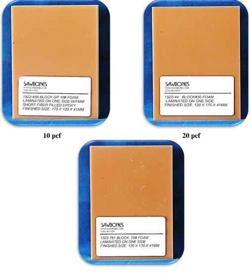
Artificial Bone Block:
Experimental artificial bone blocks were used in this in-vitro study was made by
Sawbones© (Sawbones; Pacific Research Laboratories Inc, Vashon Island, WA, USA). The bone blocks included in this in-vitro study had three combinations of differing densities
(Fig.1) 10pcf, 20pcf and 30pcf (pcf is pounds per cubic foot).56,76,125 Each artificial bone block used in the study was custom made by the company having 120 x 170 x 41mm
dimensions with a 1mm thick cortical bone made of epoxy filled sheet laminated on
cancellous bone of varying density. Mechanical properties of the synthetic bone blocks are
given in the table 1.
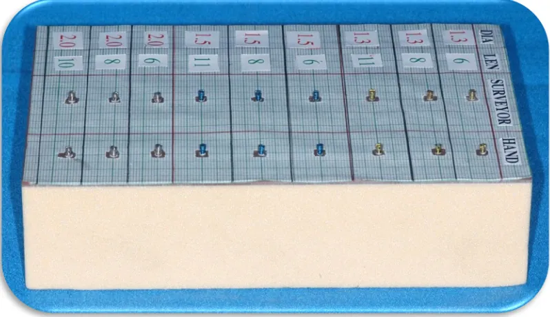
Each bone block was calibrated using graph sheet which was stuck on the surface of
1mm cortical thickness epoxy sheet (Fig.2). Using the graph sheet bone blocks were divided
into 4 different columns. First column denotes different lengths (6mm, 8mm and 10mm) of
MSI used. Second column denotes the different diameters (1.3mm, 1.5mm, and 2mm) of
MSI. A third and fourth column denotes the methods of MSI placement using the surveyor
method (guide) and the free hand placement respectively. A midpoint of each square is
marked on the graph sheet, where the MSI of various lengths and various diameters will be
inserted perpendicularly either using the surveyor method (guide) or the free hand placement
33 Method of MSI insertion
Two methods of MSI insertion were used,
• First method of MSI insertion was with the help of surveyor to mimic clinical
situation using a guide and
• Second method of MSI insertion was free hand placement without a guide.
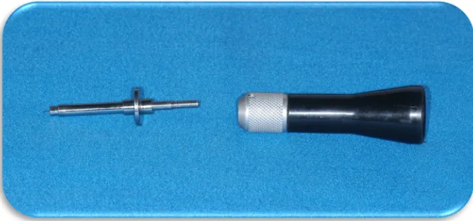
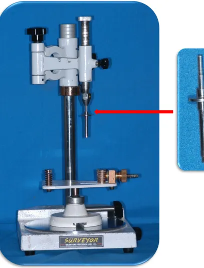
Surveyor method (Guide)
A surveyor by Saeshin Company (Saeshin Precision Co., Ltd., Korea) was used as a
guide for perpendicular insertion of the MSI. The MSI screw driver provided by the company
(S K surgical) had to be modified to fit into the surveyor assembly (Fig.3).The surveyor unit
has a spring located at the top of the assembly which was removed so that it does not give
any recoil force on the hand of the operator while inserting MSI. Tilt-top stand in the
surveyor to keep the dental cast was removed so that uniformly flat surface was provided to
place the artificial bone block. The pin and tube device of the modified MSI screw driver was
fitted in the surveyor assembly (Fig.4).
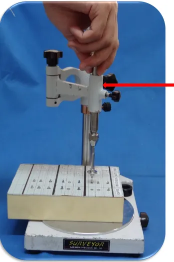
In the surveyor guided placement method, the MSI were inserted using the modified
MSI driver which was attached to the surveyor (Fig.5). MSI head was locked in the modified
MSI driver to obtain a firm grip. It was ensured that each MSI was inserted in the
perpendicular direction; it also prevented wobble of the driver during insertion. After
engaging the MSI head, the tip of the MSI contacted the surface of the artificial bone block
perpendicularly at the pre-determined point calibrated on the graph. The modified MSI driver
was rotated in clockwise direction with finger pressure until the point right before head of the
34
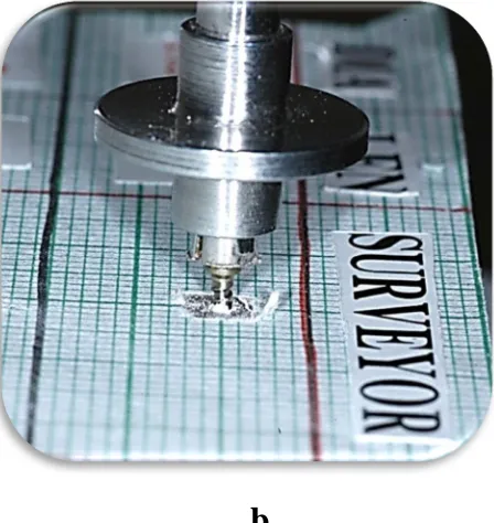
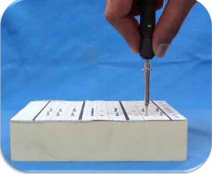
Free hand placement was defined as MSI placement using regular MSI driver
provided by company without a guide according to the manufacturer’s instructions. In the
free hand placement method the MSI head was locked in the MSI driver to obtain a firm grip
(Fig.7). It was ensured that each MSI was inserted in the perpendicular direction; it also
prevented wobble of the driver during insertion90,91 (Fig.8 a, b, c and d). After engaging the MSI tip to contact the artificial bone block perpendicularly at the pre-determined point, the
operator rotates the MSI driver in a clockwise direction with a finger pressure until the point
right before head of the MSI came in contact with the bone surface (Fig.9 and 10)
The above methods of MSI insertion were done in the 3 different bone density blocks
(10pcf, 20pcf and 30pcf) respectively. A CBCT scan was done for each bone block after MSI
insertion.
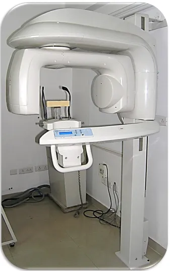
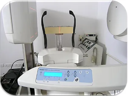
Cone Beam Computed Tomography (CBCT) scanand analysis
A cone beam computed tomography (CBCT) scan was done for each artificial bone
blocks having 3 different bone densities (10pcf, 20pcf and 30pcf) were taken respectively.
Each bone block was placed on the stand provided in the CBCT unit. A median beam line
was used to centre the artificial bone block and the head-holding rod was used to hold the
bone block in a stationary position (Fig.12).
CBCT scans for the experiment study were performed using a Kodak 9500 unit
(Kodak Dental Systems, Carestream Health, Rochester, NY, USA) with the following
standardized parameters : 90 Kv; 4Ma; Field Of View (20 X 18 cm);acquisition time 24
35
communications in medicine (DICOM) file by using the Kodak Dental Imaging Software 3D
Module Version 2.4.
Measurements:
Measurements are carried out by the following criteria:
The Kodak software provided along with the cone beam computed tomography scan
(CBCT) was used to measure the angular deviations of MSI. Tools for angular measurement
provided along with the software were used in the study (Fig.13). In each scan the
measurements were obtained in mesio-distal or horizontal (view 1; Fig.14) and
occluso-gingival or vertical (view 2; Fig.16). In each bone block a perpendicular plane was
constructed on the bone surface to measure the angular deviation of the inserted MSI. The
long axis of each MSI inserted perpendicular into the bone block was marked using the point
tools provided in the CBCT scan from the center of MSI head to the tip of the MSI. The long
axis was then superimposed on the constructed perpendicular on the bone surface to obtain
the degree of MSI angular deviation in both mesio-distal plane or horizontal (View 1) and
occluso-gingival or vertical plane (View 2) respectively (Fig.15 and.16). Measurements were
recorded in degree. If the angular deviation of MSI was 1 degree or less than 1 degree, it was
considered as an acceptable angular deviation. If the angular deviation of MSI were more
than 1 degree, it was considered as an unacceptable angular deviation. Measurements of
angular deviation were recorded in both views (View 1) and (View 2) respectively to assess
which factors were responsible for the angular deviations (various lengths, various diameters,
36
day interval to reduce intra-observer variability.
Statistical analysis:
Data entry and statistical analysis was performed with using the SPSS v.15 (SPSS
Inc., Chicago, Illinois, USA). Descriptive Statistics was done for assessing the angular
deviation with respect to varying lengths, varying diameters, different bone densities and
methods of MSI insertion. Descriptive statistics were done to find the lowest and highest
values of each group, as well as the mean value and standard deviations. To evaluate the
significance of the individual parameters influencing the angular deviation One Way
ANOVA Test with 95% confidence interval was performed. Cross Tabs Analysis were done
to find out the acceptable and non-acceptable degree of angular deviation of MSI. Univariate
Logistic Regression was done to assess the major factor influencing the angular deviation of
30 pcf
[image:46.612.67.474.83.618.2]
[image:48.612.324.548.60.297.2]
c d
a b
[image:50.612.82.531.125.606.2]c d
Figure 9: All MSI’s Inserted In Synthetic Bone Block.
[image:51.612.85.553.442.625.2]37
RESULTS
I. One Way ANOVA presented with 95% C.I
• For diameter (Table 5)
In the mesio-distal plane (view 1) as diameter increases from 1.3mm, 1.5mm and 2mm the
mean angular deviations also correspondingly increased from 1.640, 1.90 and 2.40 respectively with a significant P value (0.000). In the vertical plane (view 2) as diameter increases from
1.3mm, 1.5mm and 2mm the mean angular deviations also correspondingly increased from
1.40, 1.50 and 1.90respectively with a significant P value (0.000). Hence it can be safely
concluded that angular deviation of MSI increases with increase in diameter of MSI.
• For length (Table 6)
In mesio-distal plane (view 1) as length increases from 6mm, 8mm and 10mm the mean
angular deviations also correspondingly increased from 1.920, 1.970 and 2.10 respectively with a P value of .341 which is not considered statistically significant. In (view 2) as length
increases from 6mm , 8mm and 10mm the mean angular deviations also correspondingly
increased from 1.20, 1.70 and 1.80 respectively with a significant P value (0.000). Hence it can be concluded that angular deviation increases with increase in length of MSI in vertical plane
(view 2).
• For bone density (Table 7)
In mesio-distal plane (view 1) as bone density increases from 10pcf, 20pcf and 30pcf the
mean angular deviations also correspondingly increased from 10, 2.40 and 2.50
38
1.70. View 2 has a P value of .000 showing high statistical significance. Hence, it can be concluded that angular deviations of MSI were maximum with 30pcf bone density in
mesio-distal plane (view 1) and 20pcf in the vertical plane (view 2).
• For method (Table 8)
In mesio-distal plane (view 1) between hand and surveyor group mean angular deviations
were 2.60 and 1.40 respectively. View 1 has a P value of .000 showing high statistical
significance. In vertical plane (view 2) between the hand and surveyor group the mean
angular deviation were 1.70 and 1.50 respectively. View 2 has a P value of .000 showing high
statistical significance. Thus we conclude that angular deviations with free-hand MSI
insertion were high compared to guided MSI insertion in both mesio-distal (view 1) and
vertical plane (view 2).
II. Cross Tabs with Chi Square
• For diameter (Table 9)
In mesio-distal plane (view 1) it can be seen that as the diameter increases from 1.3mm ,
1.5mm and 2mm the number of acceptable MSI placements in (view 1) were 107 (45%) , 52
(22%) and 77 (33.6%) respectively. Along with it the number of non-acceptable MSI
placements were 73 (24%), 128 (42.1%) and 103 (33.9%) respectively. In vertical plane (
view 2) that as the diameter increases from 1.3mm , 1.5mm and 2mm the number of
acceptable MSI placements were 101 (38.4%) , 94 (35.7%) and 68 (25.9%) respectively.
39
112 (40.4%) respectively. (View 1) and (view 2) both had a P value of .000 and .001
respectively showing high statistical significance.
Hence we conclude that angular deviation was increased beyond 10 to make MSI placement
non-acceptable most frequently with the 1.5mm diameter group as compared to 1.3mm and
2mm groups in mesio-distal plane (view 1) and with the 2 mm diameter group as compared to
1.3mm and 1.5mm groups in the vertical plane (view 2).
• For length (Table 10)
It can be seen that as the diameter increases from 6mm to 8mm to 10mm the number of
acceptable MSI placements in ( view 1) were 87 (36.9%) , 86 (36.4%) and 63 (26.7%)
respectively. Along with it the number of non-acceptable MSI placements were 93 (30.6%),
94 (30.9%) and 117 (38.5%) respectively. In view 2 that as the diameter increases from 6mm
, 8mm and 10mm the number of acceptable MSI placements were 123 (46.8%) , 69 (26.2%)
and increases to 71 (27%) respectively. Along with it the number of non-acceptable MSI
placements were 57 (20.6%), 111 (40.1%) and 109 (39.4%) respectively. (View 1) and (view
2) both had a P value of .016 and .000 respectively showing high statistical significance.
Hence we conclude that angular deviation was increased beyond 10 to make MSI placement non-acceptable most frequently w