Rochester Institute of Technology
RIT Scholar Works
Theses Thesis/Dissertation Collections
12-11-2006
Graphical microcode simulator with a
reconfigurable datapath
Brian VanBuren
Follow this and additional works at:http://scholarworks.rit.edu/theses
This Thesis is brought to you for free and open access by the Thesis/Dissertation Collections at RIT Scholar Works. It has been accepted for inclusion in Theses by an authorized administrator of RIT Scholar Works. For more information, please [email protected].
Recommended Citation
Graphical Microcode Simulator with a
Reconfigurable Datapath
by
Brian G VanBuren
A Thesis Submitted in Partial Fulfillment of the Requirements for the Degree of Master of Science in Computer Engineering
Supervised by
Associate Professor Dr. Muhammad Shaaban Department of Computer Engineering
Kate Gleason College of Engineering Rochester Institute of Technology
Rochester, New York August 2006
Approved By:
Dr. Muhammad Shaaban Associate Professor Primary Adviser
Dr. Roy Czernikowski
Professor, Department of Computer Engineering
Dr. Roy Melton
Thesis Release Permission Form
Rochester Institute of Technology
Kate Gleason College of Engineering
Title: Graphical Microcode Simulator with a Reconfigurable Datapath
I, Brian G VanBuren, hereby grant permission to the Wallace Memorial Library repor-duce my thesis in whole or part.
Brian G VanBuren
Dedication
Acknowledgments
I would like to thank Dr. Shaaban for all his input and desire to have an update microcode simulator. I would like to thank Dr. Czernikowski for his support and methodical approach to everything. I would like to thank Dr. Semeraro for discussing and helping resolve his concerns with the proposal, simulator and other thesis work. I would also like to thank Dr. Roy Melton for being able to quickly read and provide feedback on my thesis.
Abstract
Contents
Dedication. . . iii
Acknowledgments . . . iv
Abstract . . . v
Glossary . . . xiv
1 Introduction. . . 1
1.1 Objective . . . 1
1.2 Motivation . . . 1
1.3 Performed Work . . . 2
1.4 Summary of Chapters . . . 3
2 Microcode Overview . . . 5
2.1 Instruction Set Architecture . . . 6
2.1.1 Exceptions . . . 9
2.2 Datapath . . . 10
2.2.1 Datapath Elements . . . 10
2.2.2 Pipelining . . . 13
2.3 Control Unit . . . 14
2.3.1 Control Fields . . . 14
2.3.2 Microprogramming . . . 15
2.3.3 Microinstructions . . . 17
2.3.4 Microprogram Sequencing . . . 18
2.3.5 Horizontal Microcode and Vertical Microcode . . . 19
2.3.6 Different Types of Microprogram Implementation . . . 20
3 Microprogramming Tools . . . 21
3.1 Command Line Microcode Tools . . . 21
3.1.1 Micro8 Microcode Assembler . . . 21
3.1.2 AMISS . . . 22
3.1.3 STEP Development Tools . . . 23
3.1.4 Structured Microcode Development and Simulation System . . . . 25
3.1.5 MX Simulator . . . 25
3.2 Graphical User Interface Microcode Tools . . . 26
3.2.1 µCS . . . 26
3.2.2 CPU Sim . . . 27
3.2.3 Little Man Microcode Simulator . . . 27
3.2.4 MythSim . . . 28
3.2.5 Motivation . . . 29
3.3 Implemented Microcode Simulator . . . 30
3.3.1 Implementation Choices . . . 32
3.4 Conclusion . . . 33
4 Microprogram Assembler . . . 34
4.1 Microprogramming Language . . . 34
4.1.1 Complex Microinstruction Format . . . 35
4.1.2 Control Fields . . . 36
4.1.3 Simple Microinstruction Format . . . 39
4.2 Microprogram Parsing . . . 40
4.3 Microprogram Verification . . . 41
4.4 Configuration of the Control . . . 42
4.5 Implementation Details . . . 44
4.6 Conclusion . . . 46
5 Datapath Depiction and Configuration . . . 47
5.1 Visual Depiction of a Datapath . . . 47
5.1.1 Graph Theory . . . 51
5.2 Reconfiguration of Datapath Components . . . 52
5.2.1 Placing and Moving Wires . . . 52
5.2.2 Signal Name Configuration . . . 54
5.2.3 Component Configuration . . . 55
5.4 Student Version’s Datapath Editor . . . 60
5.5 Grammars Used . . . 61
5.5.1 Comments . . . 61
5.5.2 Datapath Grammar . . . 61
5.5.3 Memory Grammar . . . 65
5.5.4 Expression Grammar . . . 65
5.6 Implementation Details . . . 67
5.7 Conclusion . . . 71
6 Simulation. . . 72
6.1 Signals . . . 72
6.2 Datapath Components . . . 73
6.2.1 Ordering Of Datapath Components . . . 74
6.2.2 Expression Language Evaluation . . . 76
6.3 Control . . . 77
6.3.1 Microinstructions . . . 78
6.3.2 Next Microprogram Counter . . . 78
6.3.3 Calculating CPI . . . 79
6.4 Execution . . . 79
6.4.1 Backwards Execution . . . 80
6.4.2 Displaying Simulation Results . . . 80
6.4.3 Microprogram Highlighting and Breakpoints . . . 81
6.4.4 Simulation Animation . . . 82
6.5 Implementation Details . . . 82
6.5.1 Testing and Validation . . . 84
6.6 Implemented Simulator Comparison and Results . . . 85
6.6.1 Implementation Size Comparison with Other Microprogramming Tools . . . 85
6.6.2 Performance Comparison of Various Datapaths . . . 86
6.6.3 Performance Comparison with MythSim . . . 88
6.6.4 Performance Comparison with AMISS . . . 89
6.7 Conclusion . . . 90
7 Conclusions . . . 91
7.1 Salient Features of the Implemented Simulator . . . 91
7.3 Areas for Future Work . . . 92
7.4 Closing Remarks . . . 94
Bibliography . . . 95
A Subtract And Branch On Negative Example . . . 98
A.1 Datapath . . . 99
A.1.1 Control Fields . . . 100
A.2 Microprogram To Implement ISA . . . 102
A.3 ISA Code To Implement Multiply . . . 104
A.4 Microprogram To Implement Multiply . . . 107
A.5 Datapath File . . . 109
B Various Datapaths . . . 111
B.1 Tiny Datapath . . . 111
B.2 LMMS Datapath . . . 112
B.3 Mic-1 Datapath . . . 113
B.4 Primer Datapath . . . 114
B.5 MythSim with One Write-Back Datapath . . . 116
B.6 MythSim Datapath . . . 117
B.7 AMISS Datapath . . . 118
C User Documentation . . . 119
C.1 Overview . . . 119
C.2 Creating Datapaths . . . 119
C.3 Creating MicroPrograms . . . 121
C.3.1 Control Fields Specification . . . 122
C.3.2 Datapath Macros . . . 122
C.4 Simulating It All . . . 122
C.5 ISA Language . . . 123
C.5.1 Comments . . . 123
C.5.2 Simple Numbers . . . 123
C.5.3 Intel Hex Format . . . 124
C.5.4 SRecord Hex Format . . . 124
C.6 Microprogram Language . . . 125
C.6.2 Microinstruction Format . . . 125
C.6.3 Simple Microinstruction Format . . . 126
C.6.4 Macro Format . . . 126
C.7 Expression Language . . . 126
C.7.1 Comments . . . 127
C.7.2 Defining Constants . . . 127
C.7.3 Signal Names . . . 128
C.7.4 Operations . . . 129
C.7.5 Programming Language Statements . . . 131
C.8 About . . . 133
List of Figures
1.1 A Sample Screenshot of the Implemented Simulator . . . 2
2.1 A Simple Model of Computers and Applications . . . 5
2.2 Memory Snapshot For Sample SBN Instruction . . . 9
2.3 SBN Datapath with Datapath Elements Named . . . 11
2.4 Pipelining Example . . . 13
2.5 Microprogrammed Control Unit and Datapath Overview . . . 16
2.6 Hierarchy of Instruction and Microprogram Code . . . 17
3.1 Sample AMISS Output for a Single Cycle . . . 23
3.2 Little Man Microcode Simulator Interface [3] . . . 28
3.3 MythSim Interface [26] . . . 29
3.4 Another Sample Screenshot of the Implemented Simulator . . . 31
4.1 Datapath Macros Dialog . . . 42
4.2 Control Configuration Dialog . . . 43
4.3 Microprogram Editor . . . 44
4.4 Collaboration Diagram For The Control Implementation . . . 45
5.1 Adder, ALU, Demux and Mux Components . . . 48
5.2 Constant, RAM, Register File, and Signal Viewer Components . . . 48
5.3 Register and Pipeline Register Components . . . 50
5.4 SBN Datapath with Datapath Elements Named . . . 50
5.5 A Datapath With All The Vertices Numbered . . . 52
5.6 Wire Drawing Mode State Diagram . . . 53
5.7 Signal List Window . . . 54
5.8 Custom Component Configuration Dialog . . . 56
5.9 Register Component Configuration Dialog . . . 57
5.10 Memory Component Configuration Dialog . . . 58
5.11 Screenshot With The SBN Datapath Loaded . . . 59
5.13 Collaboration Diagram For The GUI Implementation . . . 68
5.14 Collaboration Diagram For The Component Inheritance Usage . . . 69
5.15 Collaboration Diagram For The Expression Inheritance Usage . . . 70
6.1 Directed Acyclic Graph for SBN Datapath’s Non-clocked Components . . . 75
6.2 Expression Tree Example . . . 77
6.3 Collaboration Diagram For The Simulator Implementation . . . 83
6.4 Datapath Properties Dialog For The SBN Datapath . . . 86
A.1 Subtract And Branch On Negative Datapath . . . 99
A.2 Microinstruction Format for Example SBN Datapath . . . 100
B.1 Sample Datapath Screenshot: tiny.dp . . . 111
B.2 Sample Datapath Screenshot: lmms.dp . . . 112
B.3 Sample Datapath Screenshot: mic1.dp . . . 113
B.4 Sample Datapath Screenshot: primer.dp . . . 114
B.5 Sample Datapath Screenshot: mythsim 1write.dp . . . 116
B.6 Sample Datapath Screenshot: mythsim.dp . . . 117
B.7 Sample Datapath Screenshot: amiss.dp . . . 118
C.1 ISA Code Example Using Intel Hex Format . . . 124
List of Tables
2.1 Control Fields Mnemonics for SBN Datapath’s zdest Control Field . . . 15
6.1 Implementation Line Count Comparison To Other Microprogramming Tools 85 6.2 Simulation Performance For Various Datapaths . . . 87
6.3 Simulation Performance For Various MythSim Datapaths . . . 88
6.4 Simulation Performance Comparison To AMISS . . . 89
A.1 Control Fields and Their Mnemonics for SBN Datapath . . . 101
Glossary
A
arithmetic logic unit (ALU) a datapath element that performs specified arithmetic op-erations, p. 11.
B
Backus Naur Form (BNF) a formal notation to describe the syntax of a language, p. 40.
branching Modification of the program flow to use an instruction address to one that does not follow the current instruction when a specific condition is satisfied, p. 7.
C
central processing unit (CPU) see processor, p. 10.
clock cycle a measure of the length of time for one clock cycle for the processor, p. 10.
computer organization the overview of computer design, p. 3.
E
edge used to connect vertices together indicating relationships between the vertices, p. 51.
exception any unscheduled procedure call, also called interrupt, p. 9.
F
firmware is the microprogram as it is implemented into a memory store, also known as microcode store, p. 20.
G
graph a set of vertices connected to each other through edges to show the relationships between the data the vertices represent, p. 51.
graphical user interface (GUI) a way for a software program to display information to the user using elements such as windows and dialogs, p. 1.
grid snap a constraint technique that forces elements that users drag to snap to a grid [13], p. 52.
I
input and output (I/O) the input and output to a system unit such as the processor, p. 6.
instruction set architecture (ISA) the architecture as it is used for a software pro-gram, p. 5.
J
jumping Modifying the program flow to use an instruction address to one that does not follow the current instruction, p. 7.
M
Manhattan routing a constraint technique that forces all wires to be orthogonal, p. 52.
microinstuction a single line of microcode that sets the control signals for a single cycle of execution, p. 18.
microprogram a collection of microinstructions that include microinstruction branch-ing logic, p. 20.
microprogram counter (MPC) used to indicate the next microinstruction address in the microprogram to execute, p. 18.
microword the actual value used by a microinstruction to store in firmware, p. 22.
minimal instruction set computer (MISC) an ISA that uses only a few instructions and is RISC philosophy taken to an extreme, p. 99.
P
portability a measure of how many different machine platforms a piece of software can run on, p. 22.
processor the unit that contains a datapath and control unit to perform operations of the system, p. 6.
R
random access memory (RAM) a typical type of memory that allows non sequential access for reading and writing of data, p. 12.
read only memory (ROM) a type of memory that allows reads but does not allow writes, p. 12.
rubberbanding a technique to draw lines that displays the line being drawn as the user keeps the mouse button held down to specify the ending location of the line [8, page 382], p. 53.
S
subtract and branch if negative (SBN) an instruction set architecture that has only one instruction, the subtract and branch if negative, described in detail in Ap-pendix A, p. 7.
V
Chapter 1
Introduction
1.1
Objective
Microcode is beneficial since its simplicity can reduce the possible errors and the time to develop part of the processor. In the 1980s and 1990s there were several microcode simu-lators that were text based but could adapt to be used for many different processors. The recent trend in microcode simulation is to use a graphical user interface (GUI). However, there is no available microcode simulator that provides a graphical user interface and high adaptability to different processors. By adding a graphical user interface to a reconfig-urable architecture simulator, modifications can be performed on the processor diagram rather than using a text editor.
1.2
Motivation
1.3
Performed Work
Figure 1.1: A Sample Screenshot of the Implemented Simulator
The implemented simulator completed the main goals and resulted in many features including the ones shown in the sample screenshot in Figure 2.1. The salient features of the implemented simulator include:
• Provides a datapath editor similar to circuit editor which is not included by other microcode tools.
• Provides many components including an adder, an ALU, a constant, a demultiplexer, a multiplexer, a pipeline register, a RAM, a register, and a register file.
several added constructs and a namespace to decouple the expression from the datapath diagram.
• Microprogram format with symbolic names, macros and line labels, including a spe-cial isa line label to indicate when an ISA level instruction starts.
• Provides several simulation options including running for a specific iteration count (1, 10, 100, 1000, 1000000), run to a specific iteration, run to a specific micro-instruction, and simulation animation.
• Provides easy access to simulation results including updating the datapath editor with signal values, iteration number, and microprogram counter, and updating the inte-grated microprogram editor by highlighting the current microinstruction.
• Provides the CPI for a simulation run.
• Provides an integrated number converter for different bases.
1.4
Summary of Chapters
Chapter 2 overviews the basics of computer organization and microprogramming. Chap-ter 3 overviews a variety of microcode assemblers and simulators and provides a list of features desired in a new microcode simulator. In Chapter 4, Chapter 5, and Chapter 6, various aspects of the implemented simulator are detailed. Chapter 4 overviews the control and microprogram portion of the developed microcode simulator. Chapter 5 overviews the graphical user interface of the developed microcode simulator. Chapter 6 overviews the details of the simulation engine for the developed microcode simulator. Chapter 7 summa-rizes the developed microcode simulator and possible future capabilities that could enhance the simulator.
Chapter 2
Microcode Overview
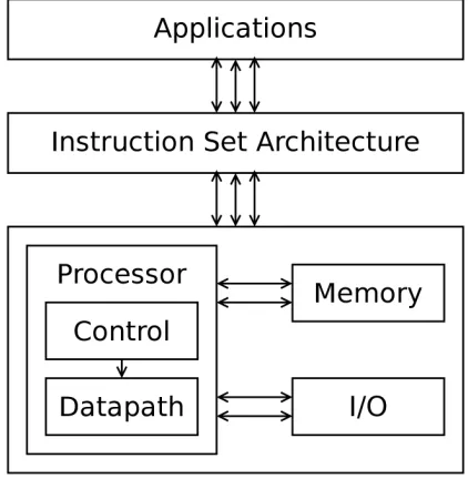
[image:23.612.204.415.373.589.2]The object of any computer system is to run applications. Applications are developed and compiled using specific instructions for a instruction set architecture (ISA). The instruction set architecture allows different computer systems that conform to the ISA specifications to run the same compiled applications.
Figure 2.1: A Simple Model of Computers and Applications
specifications.
The processor is the central processing unit of the system that performs operations of the system. As shown in Figure 2.1, the processor interacts with memory, input and output (I/O), and other subsystems. The processor is comprised of a datapath and control unit as shown in Figure 2.1. The control dictates the operations for the datapath to perform and uses the state of the system to determine the next set of controls. The datapath performs the bulk of the operations of the system. The memory component stores both the application instructions and the application data for all the applications running on the system. The I/O channels are used to connect the system to other devices such as disks, keyboards, mice, monitors and other processor systems. The culmination of the processor, memory and I/O are a simple computer system and provide the architecture for the ISA as shown in Figure 2.1.
The rest of this details different aspects of computer organization as they relate to mi-croprogramming. In particular, instruction set architectures, datapaths, and control units will be overviewed.
2.1
Instruction Set Architecture
Every instruction set architecture has locations to read and store data. These locations can be accumulators, registers, or memory. Accumulators are registers used to read data for every instruction and store data for every instruction. Registers are used in groups and can be indexed to indicate which registers are being used for inputs and which registers are being used for outputs so that different registers can be used for different instructions. Memory is used in the same manner as registers. However, since memory provides a huge store of data, it has slower access time for loading and storing data compared to registers.
A majority of instructions are in a sequential order, meaning that one instruction follows another instruction and they are stored sequentially. The program counter (PC) points to the current instruction address. During a sequential instruction, the program counter is incremented by the length of the instruction so that the program counter points to the following instruction to indicate that it is the next instruction to execute.
However, there are additional instructions that modify the sequence of instructions by changing the program counter to point to an instruction other than the next sequential in-struction. When an instruction always modifies the program counter it is called jumping. When an instruction modifies the program counter when a certain condition is satisfied it is called branching. The jump type instruction modifies the program counter to a specified in-struction address. The branch type inin-struction jumps if a certain condition is satisfied, such as the result of an arithmetic operation being zero. Otherwise the branch type instruction uses the next sequential instruction. The call subroutine and return from subroutine in-structions allow the program to jump to another sequence of inin-structions and return to the current sequence of instructions. This is accomplished by storing the next program counter value in some location (such as memory) when the call subroutine instruction is specified. Then when the return from subroutine instruction is specified, the program counter is re-stored from the same location to return to the sequence of instructions following the call subroutine instruction.
Each instruction usually consists of an opcode and operands. The opcode specifies the instruction and the operands specify how to perform the instruction. Since opcode values are difficult to remember, instruction mnemonics are assigned for each opcode. Sample in-struction mnemonics are ADD, LOAD, and JUMP. Typical inin-struction operands are register indexes, memory addresses, branch addresses, and constant values.
within a instruction’s execution. These intermediate registers are not visible to the ap-plication since they are not specified by the ISA. The instruction performs a subtraction and stores the result in the minuend’s memory address. If the result of the subtraction is negative, it branches to a specified instruction address. Otherwise, the next sequential instruction is executed. While this architecture is relatively simple, it is fully capable of performing any computational task if given an infinite amount of memory.
The instruction mnemonic for the subtract and branch if negative instruction is sbn. The operands follow the mnemonic as in the following example:
sbn negone, zero, loop
The above instruction is part of the ISA code example that implements multiply in Section A.3. This instruction subtracts the value at memory location specified by zero from the value at memory location specified by negone and stores the results in the memory location specified by negone. If the values of negone and zero are -1 and 0 as their names imply, negone will be unaffected by subtracting zero. The subtraction will be negative so that the program counter will be set to instruction address specified by loop. If zero remains zero and negone remains -1, this instruction will always jump to the instruction address specified.
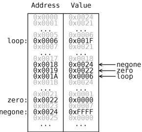
Figure 2.2: Memory Snapshot For Sample SBN Instruction
sbn 0x0024, 0x0022, 0x0006
This means that it uses memory addresses 0x0024 and 0x0022 for the subtraction and 0x0006 for the branch address. It is just more convenient for a ISA programmer to use labels for memory locations since code modifications can easily move these locations to different locations.
2.1.1
Exceptions
is handled, program control is returned to the program that was interrupted.
For each exception, an exception procedure address is saved in an exception lookup table. This allows the control to know where to jump when an exception happens. To avoid affecting the interrupted program, the state of the program is saved so that the state can be restored at the end of the exception handler. This at least requires storing the pro-gram counter so that the propro-gram counter can be restored after the exception procedure is completed.
2.2
Datapath
Hennessy and Patterson define a datapath as “the component of the processor that performs arithmetic operations” [17]. The control unit dictates to the datapath what operations to perform according to the instructions in the program. Together, the datapath and control unit are called the processor, or central processing unit (CPU). The processor coordinates the system resources (such as I/O, memory and other processors) and provides the interface specified by the ISA.
At the logic design level, a clock cycle is the unit of time for the datapath to perform a set of the control’s commands. The clock cycle can be the time to execute one ISA instruction. However, many modern systems only do a portion of the instruction in a single clock cycle in an effort to improve the speed and performance of the processor.
Next, the datapath elements that comprise a datapath will be detailed. Afterwards, one of the most important datapath optimizations, pipelining, will be reviewed.
2.2.1
Datapath Elements
The datapath is composed of many different types of function performing elements. Many common datapath elements are adders, arithmetic logic units, comparators, demultiplexers, memories, multiplexers, and registers.
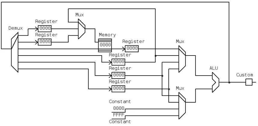
Figure 2.3: SBN Datapath with Datapath Elements Named
named. The datapath contains a demultiplexer (labeled as Demux), a few multiplexers (la-beled as Mux), a memory, an ALU, a custom element, two constants, and several registers. The same datapath is presented in Appendix A in Figure A.1. However Figure A.1 is labeled with the control field names and a few comments.
Adders perform the single operation of adding operands together. Adders typically add two operands together and are useful for incrementing the program counter or determining the next instruction address for a relative branch.
Comparators are used to compare operands (such as equal to and less than). They are mainly used to help control signals to determine what operation to perform on one or more of the operands being compared.
the instructions in the ISA.
Multiplexers take several inputs and output a selected input. Demultiplexers perform the opposite operation; demultiplexers assign a single input to only one of the outputs. These signal selection elements are vital to a datapath in modifying the signal flow from cycle to cycle.
Memory is a large storage of data. It provides instructions for the datapath to execute, the location to load inputs for the instructions, and the location to store results of the in-structions. There are two majors type of memories, random access memory (RAM) and read only memory (ROM). RAM allows non-sequential accesses for reading and writing whereas ROM allows data only to be read and does not allow data to be written.
Memory performance has not improved as well as processor performance, and as a result a small memory is placed on many modern processors to improve the performance of memory. This memory is called cache and holds a temporary copy of a small portion of memory. Since cache is within the processor, cache is much faster to use.
Registers are used for holding temporary values of operations currently being per-formed. Since registers operate at the same speed as the processor’s clock cycles, they have the highest performance. However, there is only a small limited number of registers (usually between ten and one hundred). Sometimes groups of registers are called a register file. A register file can have any number of inputs and outputs and uses indexes to indicate which register in the register file to use for each input and output.
FFFF). Subtraction of 0 assigns the ALU output to its first input which is used to assign one register value to another location. Subtraction of -1 is the same as adding 1 and is used for incrementing the program counter. The custom datapath element in Figure 2.3 is used to determine the next microprogram counter.
Next, pipelining is overviewed as to how these datapath elements can be utilized to work on different sets of data at the same to increase the throughput of the datapath.
2.2.2
Pipelining
[image:31.612.98.527.426.646.2]Pipelining is a technique used to design processors such that the actual execution of several instructions is done in parallel to maximize the use of the components of the processor as much as possible. This is possible since a single instruction can be broken into several sequential stages. Then each sequential stage can be performed one cycle at a time allowing other instructions to be executing different stages at the same time. Therefore all the stages can pass their results into their next stage at the end of the cycle to allow the processor to perform the next stages on all the instructions being pipelined.
Figure 2.4: Pipelining Example
the execution into five stages: Fetch, Decode, Load, Exec, and Store. The figure shows instructions in the rows and the instruction cycles in the columns. The first four cycles are devoted to filling the pipeline. Once the pipeline is filled (cycle 4 in the figure), every cycle has an instruction completing and four other instructions in progress. The cycles per instruction (CPI) of a pipelined processor is theoretically one since one instruction completes every cycle.
However, sometimes instructions cannot be parallelized completely such as when an instruction requires the previous instruction’s results and are called pipeline stalls. Some pipeline stalls can be shortened or avoided by using forwarding techniques. In some cases, compilers can reorder the instructions to try to avoid pipeline stalls (but still maintain the same execution results). A pipeline stall will increase the CPI for a given program since an instruction will not complete every cycle.
2.3
Control Unit
The job of the control unit is to set the control fields for the datapath to execute the program written for a given ISA.
Next, the fundamental output of the control unit, control fields, will be described. Then microprogramming, microinstructions, microprogramming sequence, different types of microprogram formats, and different types of control implementation will be detailed.
2.3.1
Control Fields
The control fields are the control fields needed by the datapath to determine the operation of all the datapath elements. Sometimes multiple datapath elements use the same control field. Sometimes a datapath element uses multiple control fields. In addition, there are control fields that are used by the control unit to determine its next state.
field values.
Control Field Mnemonics
Each control field performs different operations within the datapath based on the control field’s value. These different operations can be given names that are called control field mnemonics. These mnemonics describe the operation the control field value specifies. For example, Table 2.1 shows the control field mnemonics and their respective control field values for the zdest control field in the SBN datapath. Using the table, the control field mnemonic ztopc would assign the value 3 to the control field zdest. The datapath for the SBN (as shown in Figure 2.3 and Figure A.1) will use the control field value as a select for the demultiplexer to send the output of the ALU into the PC register. The entire listing of all the control fields and their respective mnemonics for the SBN datapath is in Table A.1 in Appendix A.
Table 2.1: Control Fields Mnemonics for SBN Datapath’s zdest Control Field Control Field Mnemonic Control Field Value
ztoaaddr 0
ztobaddr 1
ztomem 2
ztopc 3
ztoa 4
ztob 5
Microprogramming makes extensive use of control field values and control field mnemon-ics to provide the control field values during execution.
2.3.2
Microprogramming
the next microinstruction. Microprogramming is beneficial since its simplicity can reduce the possible errors in the control unit and reduce the time to develop the control unit.
Figure 2.5: Microprogrammed Control Unit and Datapath Overview
Figure 2.5 shows the connectivity between the microprogrammed control unit basic components and the datapath. The control fields are represented by the arrows from the microprogram store to the datapath and are used to control the datapath’s operation. The control fields are also used along with the status of the datapath in the microprogram se-quencing logic to determine the next microprogram counter. The microprogram counter is used to lookup the next microinstruction.
Within the processor view of the software, a microprogrammed processor has two lev-els of code being executed: the instruction level code and the microprogram level code. Each instruction is stored in memory, and its execution involves the execution of one or more microinstructions. Each microinstruction specifies to the datapath the small steps to perform that result in performing the ISA level instruction. Many simple instructions use only a few microinstructions. More complex instructions may use many microinstructions including loops of microinstructions. The more microinstructions an ISA instruction has associated with it, the longer the execution time of the ISA instruction is.
Figure 2.6: Hierarchy of Instruction and Microprogram Code
instruction previously analyzed in Section 2.1. The figure uses the microprogram detailed in Section A.2 of Appendix A. The figure shows how the one instruction in the ISA cor-responds to nine microinstructions (a majority of which are fetching the instruction and its operands). The microinstructions are executed sequentially by the processor. Since every ISA level instruction using this microprogram uses nine microinstructions, the resulting cycles per instruction (CPI) is 9. Each microinstruction has a set of control field values that it sends to the datapath to execute the steps necessary to fetch, decode and execute the ISA instruction.
2.3.3
Microinstructions
A microinstruction contains all the control fields for the datapath’s controls. Each different microinstruction controls the datapath to perform a different operation. Additionally, the microinstruction specifies how to determine the next microinstruction.
Typically, the ISA instructions are implemented as one or more microinstructions. Since many instructions perform similar tasks, such as reading data values from memory, the same microinstruction may be used by several instructions to reduce the microprogram length.
there are other tasks performed by the microprogram. These include decoding an instruc-tion’s opcode and performing exception handling. Both of these typically require advanced microprogram sequencing to perform the task optimally.
2.3.4
Microprogram Sequencing
The current microinstuction is addressed by the microprogram counter (MPC). Many micro-instructions flow sequentially, and the MPC is incremented by 1 to indicate the following microinstruction. However, the power of microprogramming comes from its ability to pro-vide more sophisticated sequencing techniques.
One such sequencing technique is to give the address for the next instruction to allow jumps in the microprogramming sequencing. This allows a microinstruction to jump back to the beginning of the ISA instruction decode to evaluate the next ISA instruction.
Another sequencing technique is to allow branches in the microinstruction. This can be done several ways. One way is to specify the branch address to use if the branch condition is met and if the branch condition is not met then continue with the next microinstruction. Another way is two specify both addresses for the branch taken and the branch not taken cases. And yet another way is to specify an address that is modified using the branch value (0 or 1) which results in two different addresses.
One of the more advanced microsequencing techniques involve specifying an address that is modified by a value from the datapath to provide many microinstruction addresses and is useful for decoding microinstructions.
Just Another Microsequencer
Many of the advanced microsequencing techniques are implemented by Just Another Mi-crosequencer (JAM) [24]. The miMi-crosequencer is a VLSI design that implements very flexible microprogram sequencing.It supports advanced microinstruction sequencing used in different commercial processors including N-Way branch, N-Way call, N-Way return, conditional branch, conditional call, conditional return, and loop control.
The microinstruction sequencer has a branch address input, a branch condition input, a branch mode input, and a program counter output.The sequencing type is specified by the branch mode input [24]. Also, the branch mode can be set to 6 to indicate the branch address is the N-Way mask.This mask is used to indicate which bits of the branch address to combine the current program counter register to calculate the next program counter.An internal stack (with 8 levels) provides the mechanism for storing and retrieving program addresses for calls, returns, and loops.
2.3.5
Horizontal Microcode and Vertical Microcode
In additional to microprogram sequencing, another software technique applied to micro-programming to try to reduce the microprogram size though vertical microcode.
microinstruction.
Microprograms can be written initially using a horizontal microinstruction format and later converted to a vertical microinstruction format to reduce the overall number of bits used to store the microprogram. As a result, many microprogramming tools do not specify a vertical microinstruction format.
2.3.6
Different Types of Microprogram Implementation
Microprogramming is just a method to develop the control unit and can be implemented in several different ways. As seen previously in Figure 2.5, the microprogram can be stored in a customized memory store within the control unit called firmware, or microprogram store. Some microprocessors allow the microprogram to be reprogrammed to allow support of another ISA. The reprogrammable firmware allows instructions to be added, instructions to be optimized, and instructions to be fixed for previous errors.
Additionally, the microcode can be implemented as a hard-wired finite state machine [17]. This hard-wired finite state machine gains all the benefits of the microcode design process without the delays and physical area associated with a hardware microprogram sequencer and microstore.
2.4
Conclusion
Chapter 3
Microprogramming Tools
Over the last three decades, various microcode assemblers and simulators have been devel-oped to meet the changing needs of microprogram writers. The following assemblers and simulators are a small portion of the available microprogramming tools and represent many of the features that are possible.
First, the command line tools will be summarized in chronological order: Micro8 Microcode Assembler (1981), STEP Development Tools (1985), AMISS (1985), Struc-tured Microcode Development and Simulation System (1990), and MX Simulator (1995). Then the graphical user interface tools will be summarized in chronological order: µCS (1992), CPU Sim (2001), Little Man Microcode Simulator (2002), and MythSim (2004). Finally, the implemented simulator will be overviewed.
3.1
Command Line Microcode Tools
3.1.1
Micro8 Microcode Assembler
on the naming conventions.
Since this is only a microcode assembler, only the control unit structure of the logic design needs to be defined instead of the entire logic design of the processor. Therefore only two input files are needed, a control unit structure and a microprogram.
The adaptability and flexibility of the microword definition is provided though the use of a very flexible control field definition. Each control field can be any size and be located anywhere in the microword to allow overlapping control fields for vertical microcode. Each control field defines mnemonics for the control field values that simplify writing a micro-program.Each control field can also specify an overflow control field used to assign any overflow to when a microinstruction assigns a value too large for a control field.
Micro8 provides extensive error checking. It provides checks for assignments that are too large (including any overflow control fields).It also checks if overlapping control fields specify conflicting default values or if a part of the microword is specified more than once within a single microinstruction.And Micro8 checks for the reuse of a microinstruction address.
3.1.2
AMISS
The AMISS tool [19] was developed through Robert J. Pesar’s Master’s Thesis, A
Micro-programming Simulation System for Educational Use. It provides a flexible simulation
environment that allows the datapath to be described behaviorally through a high-level language.The datapath definition is fairly complicated with different sections for different aspects of the processor definition.As a result, the datapath is difficult to modify for the simulator. Consequently, the datapath used at the Rochester Institute of Technology has not been modified in nine years.
the microprogram.
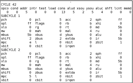
Figure 3.1: Sample AMISS Output for a Single Cycle
Figure 3.1 shows the output of a sample cycle from the AMISS tool.However, usability was not a primary concern of the simulator. The microinstruction shown at the beginning of the output does not order the control field values in the same order as the microinstruction format. Additionally, the order of the registers does not seem to have any apparent order and makes it very difficult to determine a register’s value quickly.
3.1.3
STEP Development Tools
The STEP Development Tools [27] is a commercial microprogram development system.It provides high level language constructs for both the control structure definition and the microprogram definition.It is highly flexible in many ways that allow many vastly different architectures to use the tool.
language.The language uses many common high order language-like constructs such as flow control, source inclusion and macros.
Each control field has many attributes that can be set.Some of these attributes include the position of the control field in the microinstruction, the length of the field, and a parity field for the microinstruction.The field can store signed numbers as either one’s comple-ment or two’s complecomple-ment and can reverse the bit order.Also, the field can have mnemonics specified and the legal values for the field specified.To facilitate vertical microcoding, the simulator allows fields to be defined based on the value of a specified field.This allows better vertical microcode verification since fields can be checked against another field’s particular value as to whether the field is valid for this microinstruction.
When writing microcode for STEP, the control field is specified and assigned either a numeric value or one of the mnemonics associated with the control field.It was done this way rather than have global mnemonics that set all the control fields using the mnemonic since it shows the microprogrammer’s intent and allows for better validation.The most im-pressive feature of the STEP Development Tools is the macro expression flexibility. In addition to macros accepting multiple arguments, one macro argument can appear before macro name to provide easier to read microprograms. The following examples show the
IFT macro and the< -macro:
IFT aReg < bReg goto label; aReg < - aReg - bReg;
These macros might expand to the following:
aluOp=sub, rand1=aReg, rand2=bReg, branchTest=negative, branchAddr=label;
This macro facility is one of the most impressive of any the microcode assemblers and allows for a high level language influenced constructs within the microprogram.
3.1.4
Structured Microcode Development and Simulation System
A Structured Microcode Development and Simulation System (SMDSS) [22] a limited re-configurable tool. The limitation is that the tool focuses on advanced microcode sequencing that uses a fixed method for microprogramming sequence.
The tool separates the microcode store into a control store, a sequence store and a condi-tion store.The control store contains the control values for the datapath.The condicondi-tion store and sequencing store are coordinated to determine the appropriate control store address to run next based on the given sequencing. Many of the high level sequencing constructs are available for use such as the conditional statement (if ), the multi-way statement (case), several types of loop statements (while, repeat, for), function calling statements, and the jump statement.
The tool provides a simulator for testing the microprogram sequencing but does not simulate the datapath of the processor.This tool provides excellent support for the advanced microprogramming sequencing but is very limited in scope of simulation and forces the microprogram sequencing into the defined control structure.
3.1.5
MX Simulator
The user interface defines three different interfaces.The full screen mode presents all the registers to the user with two lines for the user to input commands.An interactive command line mode uses commands for explicit displays and execution.Finally a batch mode allows the compiler and simulator to be scripted to aid teachers in grading student’s microcode.
The Pascal based microprogramming language allows operations to be specified to sim-plify the job of coding the microprogram and increases the readability of the microprogram. Since the operations and architecture are simple enough, it is relatively easy to understand how the Pascal-like operations are converted into the microinstruction control fields. Don-aldson, the author of the simulator, says that an appropriate extension of the simulator would be to allow the architecture to be redefined.
3.2
Graphical User Interface Microcode Tools
3.2.1
µ
CS
A microcode simulator for the Apple Macintosh called µCS (for microcode simulator) [10] is one of the earliest microcode simulators utilizing a graphical user interface (GUI). The microcode simulator targets a hypothetical machine architecture strongly based on the PDP-11 instruction set and influenced by useful attributes from the DEC LSI-11.This simulator was developed to be used for an undergraduate computer organization class to teach the PDP-11 instruction set.
3.2.2
CPU Sim
CPU Sim [21] is a processor simulator that involves both the instruction and the micro-programming levels.Since the simulator targets Computer Science students, the simulator focuses on the instruction set architecture. As a result the microprogramming aspect is only oversimplified macros chosen through dialogs.It allows the hardware to be described on a register transfer level and allows for a variety of processor types to be implemented.The simulator hides a majority of the hardware and microprogramming details so that only parts that affect the instruction set architecture are seen. CPU Sim is a unique simulator in how it takes and presents the processor details to the user.Since the simulator is instruction set architecture centered, it is a poor tool to use to teach microprogramming and computer organization.
3.2.3
Little Man Microcode Simulator
The Little Man Microcode Simulator [3] is a simple microcode simulator designed to pro-vide an introduction to computer organization concepts.It differs from the other micro-code simulators in that the user cannot modify the actual micromicro-code but only the instruc-tions.Figure 3.2 shows the interface for the Little Man Microcode Simulator. Since the microcode is fixed, the simulator only runs one instruction at a time and shows the register trace for the microprogram.This is useful for introducing students to the ideas of micropro-gramming while reinforcing the concepts of running a program at the assembly level.
3.2.4
MythSim
Figure 3.2: Little Man Microcode Simulator Interface [3]
Figure 3.3: MythSim Interface [26]
3.2.5
Motivation
3.3
Implemented Microcode Simulator
In the 1980s and 1990s, there were several microcode simulators that were text based with reconfigurable datapaths. The recent trend in microcode simulation is to use a graphical user interface (GUI). However, there is no available microcode simulator that uses both a visual interface with a reconfigurable datapath. After developing Micro, the author, David Magagnosc, wanted to develop another versatile graphical simulator by allowing modifi-cation to the underlying datapath [16]. Also, John L. Donaldson indicated the next logical step to improve his MX simulator tool would be to provide a means to modify the base architecture [5]. By combining a graphical user interface with a reconfigurable architecture simulator, modifications can be performed on the architecture diagram rather than using a hardware description language to generate the datapath. However, a hardware description language was still needed to load and save the configured datapaths even though it is not exposed to the user.
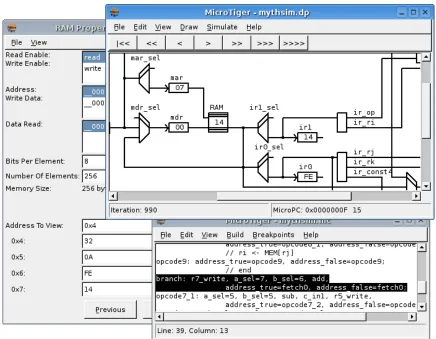
The implemented simulator completed the main goals and resulted in many features including the ones shown in the sample screenshot in Figure 3.4. The salient features of the implemented simulator include:
• Provides a datapath editor similar to circuit editor which is not included by other microcode tools.
• Provides many components including an adder, an ALU, a constant, a demultiplexer, a multiplexer, a pipeline register, a RAM, a register, and a register file.
• Provides a customizable component using a C based programming language with several added constructs and a namespace to decouple the expression from the datapath diagram.
Figure 3.4: Another Sample Screenshot of the Implemented Simulator
• Provides several simulation options including running for a specific iteration count (1, 10, 100, 1000, 1000000), run to a specific iteration, run to a specific micro-instruction, and simulation animation.
• Provides easy access to simulation results including updating the datapath editor with signal values, iteration number, and microprogram counter, and updating the inte-grated microprogram editor by highlighting the current microinstruction.
• Provides an integrated number converter for different bases.
The interface for datapath modification resembles a circuit design environment that has standard datapath structures such as ALUs, multiplexers, demultiplexers, memories, buses, and registers to enable an efficient mechanism to datapath reconfiguration. The datapath editor also allows generic datapath modules that use a built-in expression evaluation to set the outputs based on internal signals and inputs. These generic datapath modules allow for greater configuration to the datapath.
3.3.1
Implementation Choices
The C++ language was chosen as the implementation language due to its high portability and proficient speed. Java was considered since it has higher platform independence, but disregarded since it lacks the necessary speed for the simulation environment.
The wxWidgets toolkit was chosen for its high portability [9]. The GUI is a datapath editor and an observer of the simulation environment. Since the simulator is written in C++ the GUI should also be written in C++. The three major portable graphical toolkits for C++ are QT, GTK and wxWidgets. The QT toolkit is a commercially developed toolkit with Windows, Unix/Linux and Macintosh support. However, to generate a Windows executable using the QT toolkit has to be licensed. GTK is a toolkit heavily developed for Linux and ported to Windows with poor support. The wxWidgets toolkit was developed to be platform independent and supports many platforms, including Windows and Linux. For developing open source platform independent GUIs, wxWidgets seems to be the best choice.
available tool that is completely upwardly compatible with Yacc and was utilized to provide the general parsing capability for the implemented simulator [6].
3.4
Conclusion
Chapter 4
Microprogram Assembler
The main use of the microcode simulator is to aid with microprogram development and testing. The microprogram language needs to be easy to read and easy to write to aid in both development and testing. The microprogramming interface needs to be easy to use and aid in the more complex aspects of the microprogram development and testing.
This chapter overviews the control and microprogram portion of the developed micro-code simulator. First the microprogramming language will be detailed. Then the parsing and verification of the microprogramming language is overviewed. Next, the control con-figuration is detailed including how the control field mnemonics can be described to the simulator. Finally, the microprogramming implementation design is described at its high-level code design.
4.1
Microprogramming Language
Trying to implement a high level microprogramming language that corresponds to a reconfigurable datapath increases both the software implementation and the microprogram design complexity. It increases the complexity of the microprogram design since the high level constructs need specifications in how to convert the constructs into the control field values for the microinstruction. However, a lower level microprogramming language is easier for one to understand what exactly is performed by the microinstruction.
In addition, the microprogram sequencing intent would need to be fully specified for a reconfigurable datapath. Allowing the sequencing to be fully specified would require a complex interface that would be very difficult to understand. This is why a majority of reconfigurable microcode simulators do not use high level constructs. The Micro8 code assembler provides an incredibly flexible control signal definition that allows a micro-instruction to be labeled and that label to be assigned to control field values [12]. For exam-ple, this allows microprogram branching by setting a microinstruction address to a control field. Couple this with a reconfigurable datapath that controls the microprogram logic and the resulting microinstruction sequencing has the same potential power as the high level constructs.
As a result, the microprogramming language designed for the implemented simula-tor is a fairly low level microprogramming language that uses control field mnemonics, microinstruction labels and macros. These are the same type of constructs used within an assembly language.
The microprogramming language is a series of microinstructions. Each microinstruction represents the controls for a single cycle of the datapath. There are two formats of micro-instruction formats: a complex one that uses symbols to avoid memorization of control field values and a simple format consisting of a simple list of control field values.
4.1.1
Complex Microinstruction Format
is simple to write, is easy to read, and still has high flexibility. The control field mnemonics indicate a value for a control field. However, it would be tedious to make a mnemonic for every possible value. For example, assigning a mnemonic for every register file index would be pointless since the registers in a register file are usually referred to by their index anyway. Therefore the control field assignments are still very necessary and useful. The line labels allow the microprogram sequencing to specify a line of the microprogram and let the compiler determine the address of the specified microinstruction.
Microprogram Comments
As with any programming language, comments are necessary for designers to pass infor-mation to others about the details of the microprogram. The comments use both C++ style comments (“//”) and Perl style comments (“#”). Everything after the comment delimiters until the end of the line is part of the comment. It is useful to provide several standard commenting styles since they are recognizable as comments and assist new users using the microprogramming language.
4.1.2
Control Fields
There are many ways control signals are used. They can be used as enables, addresses, operation control logic, sequence control logic and more. Several of the microprogram tools reviewed in Chapter 3, including the Micro8 microcode assembler, allow every field to have user defined control field mnemonics for the control field values which can be ref-erenced within the microinstruction [12]. These control field mnemonics can give descrip-tive names to the enables, operation controls and sequence controls. This useful feature was included in the implemented simulator to allow the user to specify the operations for a microinstruction without the need to remember specific control values.
value. This is useful when a control means different things depending of the context of other signals.
However, one useful constraint on the control field mnemonics is that no control field mnemonic can be used by more than one control field. The exception to this constraint is that any number of control fields may use the special “DEFAULT” control field mnemonic. This improves clarity of the microcode since a control field mnemonic means only one assignment and does not contain assignments hidden in other control fields. This differs from the Micro8 assembler since the Micro8 assembler allows the control field mnemonics to be used in multiple control fields to assign a value to each of those control fields using one mnemonic [12]. This also differs from the STEP development tools which forced the control field name to be used in conjunction with the mnemonic requiring longer keywords to set the control value [27]. This constraint was chosen to use ideas from both: to allow global control field mnemonics without the worry about what fields may also be using the same control field mnemonic.
Additionally, Micro8 allows an overflow to be defined for each control field. When a value too large for the control field is assigned, it assigns the unassigned part of the value into the overflow control field [12]. This allows unique uses of control fields and was included in the implemented microcode simulator.
Microinstruction Labels
In addition, microinstruction labels can be numeric addresses specifying the address of the microinstruction. These are useful for microprograms that use branching techniques that require branch addresses to align against certain microinstruction addresses. These numeric labels were inspired by the required numeric labels used in Tanenbaum’s Pas-cal based microprogramming language used in the MX Simulator [5]. A sample micro-instruction with micromicro-instruction labels declared and used is:
negbranch: memtox, zerotoy, ztopc, jmpalways, jmpaddr=isa;
The microinstruction has a microinstruction label negbranch which can be used in other microinstructions to assign the microinstruction address to a control field. The micro-instruction also uses the control field mnemonics memtox, zerotoy, ztopc, and jmpalways. Also, the microinstruction uses the isa microinstruction label to assign it to the control field named jmpaddr.
Macros
Often there are groups of control signals that need to be set in a particular manner to per-form a certain higher level operation. The Micro8 assembler provided macros to meet the need to simplify the assignment of a group of control signals to perform this higher level operation [12]. Macros are just like microinstructions in that control field labels can be used, control fields can be assigned and microprogram line labels can be used. The differ-ence is that a macro is not a part of the microprogram, it is used within a microinstruction similar to a control field label to easily assign all the things assigned by the macro. Macros cannot be assigned microinstruction labels but are given macro names that are used within a microinstruction to utilize the macro.
greater flexibility. Through the use of macros, the datapath designer can simplify the micro-code by making certain universal operations for the datapath into macros.
The following is a simple example of making the previous instruction into a macro:
# defines a macro as the same microinstruction as before @macro mymicro memtox, zerotoy, ztopc,
jmpalways, jmpaddr=isa;
# use the macro to implement a microinstruction negbranch: mymicro;
The example defined a macro name mymicro that uses a few control field mnemonics and a control assign to a microinstruction label. The microinstruction below the macro definition uses the macro name and also uses a microinstruction label.
4.1.3
Simple Microinstruction Format
In the AMISS tool, the microinstruction format is very simple. It is a list of all the values for the controls [19]. This format is not the easiest to read since it requires knowing the order of the control field values in the format and what the values mean for each of the control fields. However, when writing massive amounts of microcode, this format can be easier to use after using it for a while for the same datapath. However, this simple microinstruction format cannot be mixed with the other complex microinstruction format that uses field labels and field assignment within a single microinstruction. But within a microprogram, different microinstructions can use either format and the user is not forced to use only one microinstruction format for the entire microprogram. Additionally, the control fields are sorted alphabetically for the order of the control fields values rather than having them explicitly ordered by the user.
knowledge of the control field mnemonics or control field names. This simple micro-instruction format allows this program to operate with other tools by using making a small parsing utility to convert formats to this simple microinstruction format.
The following example uses the instruction in the last example but with the simple microinstruction format instead:
# negbranch: memtox, zerotoy, ztopc, jmpalways, jmpaddr=isa; # the same microinstruction as the above line
# just uses the simple microinstruction format instead negbranch: 1 2 0 0 0 0 2 3;
4.2
Microprogram Parsing
The parsing for the microprogram and datapath macros uses Flex [18] and Bison [6] (the GNU versions of Lex and Yacc). Backus Naur Form (BNF) is a formal syntax to easily specify the grammar of a language [7]. Using the original BNF, the microprogramming language can be formally be described as the following:
<microprogram> ::= |
<microprogram> <microinstruction>
<microinstruction> ::= <microlabels> <valueslist> ; | <simpleformat> ; |
@macro <identifier> <valueslist> ; <microlabels> ::= |
<microlabels> <identifier> : <microlabels> <number> : <valueslist> ::= |
<valueslist> <identifier> , |
<valueslist> <identifier> = <identifier> , | <valueslist> <identifier> = <number> ,
<simpleformat> <number>
The BNF is implemented using Bison with additional error handling to report errors in microprograms that do not conform to the microprogram syntax. The tokens of the language are “@macro”, “:”, “,”, “;”, identifiers, and numbers. Flex is responsible for analyzing the microprogram and converting the microprogram into these tokens to be used by Bison. Additionally, Flex also removes comments from the microprogram as it converts the microprogram into tokens.
4.3
Microprogram Verification
It is better to inform the user of his or her mistakes as early as possible. When writing a microprogram, as with any programming language, there are many possible errors that can exist. The most obvious errors are due to lexical analysis where the microcode does not conform to the microinstruction format. These are easy to detect and report information to the user such as line number, the exact text that caused the failure and what the micro-program parser expected as text instead of what it received. Since the lexical analysis and parsing are done by Flex and Bison respectively, these tools provide an easy method to provide all this information to the user.
However, there are more errors than just parsing the microinstructions. Each micro-instruction line label should only be used for one micromicro-instruction to avoid ambiguity. Each label should be either a valid control field mnemonic or macro name. Also, each control field assigned should use a valid control field name and use a valid number or microinstruction line label.
The final verification of the microinstruction ensures that each control field is not be-ing forced to more than one value by the microinstruction. This is necessary since the control fields mnemonics and macros may hide the control fields being used in the micro-instruction.
Since the datapath macros do not have any knowledge of the microinstructions, the datapath macros cannot use any microinstruction line labels. This ensures the datapath macros are not forcing the microprogram to have certain defined microinstruction line la-bels.
To aid in microprogramming, the control field mnemonics along with other useful con-trol field attributes need to be configured before writing any microinstructions. These are configured through the control configuration dialog.
4.4
Configuration of the Control
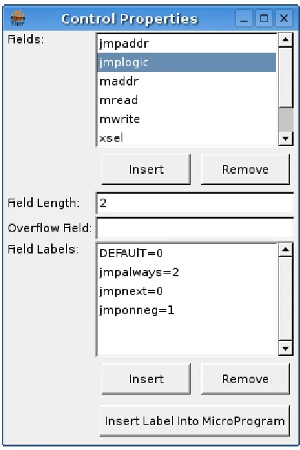
The aim of this work is to develop a graphically reconfigurable microcode simulator. That includes configuring the control unit graphically. The result is a configuration dialog that shows all the control fields. When a control field is selected, all the control field mnemonics for the selected control field are listed. Also, the control field length can be modified since control fields tend to use many different lengths that are not necessarily the same as the datapath bus width. The control field overflow can also be specified using the control configuration dialog. The control configuration dialog is shown in Figure 4.2.
Since having the datapath macros in the control configuration dialog would make the dialog seem bulky and inconsistent, the datapath macros are configured in a separate dialog. The datapath macros dialog is shown in Figure 4.1.
Figure 4.2: Control Configuration Dialog
Both the control configuration dialog and the datapath macros dialog are accessible from both the datapath editor (described in Chapter 5)and the microprogram editor (de-scribed next). The datapath editor needs to be able to modify the control and datapath macros. The microprogram editor needs to be able to review the control features that are fundamental to writing microcode.
Figure 4.3: Microprogram Editor
described in Appendix A. It allows microprograms to be easily loaded and saved, has ba-sic editing controls, and provides access to the control configuration and datapath macros. Additionally, the datapath editor shows highlighting for the current microinstruction be-ing simulated and provides breakpoint control. These simulation features are discussed furthered in Chapter 6.
4.5
Implementation Details
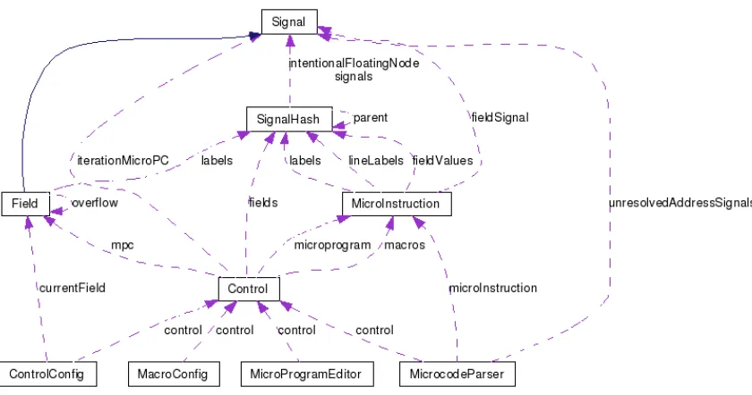
Figure 4.4: Collaboration Diagram For The Control Implementation class, MicroInstruction class, and Control class.
The Field class is derived from the Signal class. The Signal class encapsulates the signal data. The signal data can contain any number of bits, can be represented in different formats and has arithmetic functions that allow many operations to be performed on the signal data. The Field class stores the mnemonic names and values within a SignalHash class object. The SignalHash class provides a hash object for storing Signal class objects using a name. The Field class also stores the Field overflow information.
following formula:
CP I = last isa iteration−f irst isa iteration
number of isa iterations−1 (4.1)
The Control class has the microprogram counter (mpc) as a field signal (since it could be a control field). The Control class also stores the fields using the SignalHash class since the Field class is derived from the Signal class. The Control class also stores the microprogram and macros.
The ControlConfig, MacroConfig and MicroProgramEditor classes all use the control class object to view and modify various aspects of the control unit. The ControlConfig also uses the currentField variable for the control field being viewed and modified.
The MicrocodeParser is used to parse the macros and microprograms. It stores the control it is parsing for, the microinstruction currently being parsed, and the unresolved address labels. The unresolved address labels allow microinstruction labels to be used before they are declared. At the end of parsing a microprogram, unresolved address labels are reevaluated to ensure that they were declared and assign the proper values to the control fields using the unresolved address labels.
4.6
Conclusion
Chapter 5
Datapath Depiction and Configuration
The datapath consists of many datapath components and signals. Components perform operations on the signals such as a multiplexer (mux) component selecting a signal, an arithmetic logic unit (ALU) component performing arithmetic operations, or a memory component reading and writing signals into a large store of signals. Signals transfer data from component to component and represent the wires of a real processor.
This chapter overviews the graphical user interface of the developed microcode simula-tor. First, the visual depiction of the datapath is described. Then, the reconfiguration of the datapath using the graphical interface is detailed. After the datapath depiction and reconfig-uration are detailed, the datapath editor as a whole and the student version of the datapath editor are described. Then all the grammars for the datapath are described followed by a description of the overall graphical datapath software implementation is described.
5.1
Visual Depiction of a Datapath
There are many different methods to represent a datapath. Many representations use sim-ilar symbols and techniques. In particular, many datapaths have a standard symbol for multiplexers, demultiplexers, and ALU components. Wires are used to show connections between datapath components but do not show the wires for signals from the control unit (and therefore do not show the control unit).
group of signals or performing an arithmetic operation. Each component also has three types of signals associated with it. A control signal is used to determine the operation the component should perform and typical

![Figure 3.2: Little Man Microcode Simulator Interface [3]](https://thumb-us.123doks.com/thumbv2/123dok_us/120813.11637/47.612.95.528.88.399/figure-little-man-microcode-simulator-interface.webp)