Abstract- The improvement towards the use of precise control, efficient, high torque and noiseless motor for committed applications has pulled the engineers to new techniques. While thinking of improvement, most of the current researches discussed the evolve of Brush Less Direct Current (BLDC) techniques to shatter the day to day practicing models like induction motor, synchronous reluctance motor etc., The elaborate discussion made here about the speed control of BLDC motor with applying sudden load removing the same suddenly by the distinct technique. In addition the assessment are achieved among the typical Proportional Integral Derivative (PID) controller and distinct techniques known as Adaptive Neuro Fuzzy Controller (ANFC) through simulation of speed torque characteristics curves, which generated based on the parameters rising and settling time, peak over and undershoot. In this research paper, we mainly based on jerk issue occurred in speed control of BLDC motor. The way in which, we resolved this issue is clearly narrated in this work through the addition of ANFC replacing general controller.
Key words: PID controller; Adaptive Neuro Fuzzy Controller, MATLAB/SIMULINK.
I. INTRODUCTION
Commonly for stumpy power application prefers the BLDC electric motor compared to other types motors like induction motor and synchronous reluctance motor due to their maximum efficiency with excellent performance, need little maintenance, high uniform flux density, smallest problem of electromagnetic interference. BLDC electric motor is not only used for low and medium power application such as blowers, fans, washing machines, etc. it is also recommended for functioning the high power applications such as hybrid electric vehicle, air conditioning devices (HVAC), lots of industrial tool and biomedical equipments [1]-[4].
Implementing highly developed monitoring ways namely adaptive, changeable structure method and combination of fuzzy with neural group, we can easily achieve the desired speed matched by actual speed which is sensed by rotor position sensors for variation in motor parameters and sudden and gradual load disturbance in BLDCM [5].
Revised Manuscript Received on June 12, 2019
S. Swapna, Research Scholar,Department of Electrical and Electronics Engineering,/Vel Tech Rangarajan Dr. Sangunthala R&D Institute of Science & Technology, Chennai, Tamil Nadu, India.
Asst. Professor, Department of Electrical and Electronics Engineering, GRT Institute of Engineering & Technilogy, Tiruttani, Tamil Nadu, India.
K. Siddappa Naidu, Professor, Department of Electronics and Communication Engineering / Vel Tech Rangarajan Dr. Sangunthala R&D Institute of Science & Technology, Chennai.
Hybrid controller (combination of neural network with fuzzy controller) has a powerful capability to solve the structure improbability and the sudden or gradual load oscillations; however which needs large detecting technique and value acquisition system. Here the author clearly explained, implementation of fuzzy is used to stimulate the parameters in general PID based on the deviation and change in fault will be superior option to observe BLDC electric drive at low power appliance instead of former PID controller [6]-[7].
Using Lab View software simulation tool, the speed control is done in the PMBLDCM by using hybrid controller (combination fuzzy and former PID controller) gives the better performance in terms of improving the motor parameters such as settling time, rising time, delay time and peak and over shoots in the motor. Also the performance is proved by implementing the hardware realization which is done by NI-DAQ 6009 along with PMBLDCM [5].
By implementation of Active Disturbance Rejection Controller, Load torque is compensated in the rotor shaft of BLDCM for accurate control of speed in low power applications. Here, authors found the merits of this controller as not mandatory of any measuring devices to monitor the load torque in condition of maximum speed and acceleration. Also, the revision of BLDC motor is simulated by load torque variation and disturbances [6].
BLDC motor speed monitored through implementation of Model Reference Adaptive Control (MRAC) and general PID controller, also motor parameters, load variations were analyzed. Here, the purpose is to design a drive which maintain constant speed and also achieved the similar value of rotor and reference speed. Ultimately, researchers reduced the error in actual speed and focused the high performance [7].
At speed range from 15 RPM (Low Speed) to 2500 (High Speed) RPM were tested in hardware implementation while using dSPACE DS1103 controller board. Here, the researcher determined the advantages of dSPACE DS1103 controller is less execution time and low effort of experimentation in real time application. Hardware implementation of speed control of BLDCM can attained the good performance in terms of obtained accurate rotor position capacity along with data acquisition singnal using real time dSPACE DS1103 controller [8].
II.BLDC ELECTRIC SYSTEM
Fig.1 demonstrates common systematic arrangement of a BLDC motor which comprises stator and rotor as two main functional indicators. In this, stator got energized by DC supply through Voltage Source Inverter (VSI) or Electronic commutator which alters DC into AC supply. There are six switches in VSI, which were under control of trigger circuit emitted from the controller block. Hall Effect sensor sense the actual signal receiving from rotor and reference signal set by
us are analyzed in the controller circuit. The ON/OFF condition of six MOSFET stitches in electronic commutation is governed by the firing pulses released based on the error which generated in the drive circuit. The two out of three phases in the stator winding got energized at a time through upper and lower leg switches in the electronic commutator or VSI. For example, A and B phases in the stator got excited by switching ON of S1 in upper leg and S4 in lower leg.
Fig.2 Conduction states of S one & S four in VSI-fed BLDC electric motor
III. ELECTRONIC COMMUTATION (EC) IN BLDCM DRIVE
Rotor position of BLDC motor can be detected by Hall Effect sensor using electronic commutation during 60° interval. The „A‟ phase switching period of two switches (first switch & fourth switch) are appeared in Fig.2. A line current iab acquires from dc connect capacitor which extent relies upon connected dc interface voltage(Vdc). Table 1 demonstrates the switching conditions of the EC in VSI
nourishing a BLDC dependent on Hall-impact position stages (Ha − Hc).
Presently, at any occasion of time, two switches (first switch & fourth switch), in top and bottom in "ON" position, rests were different. As appeared in Fig. 6.1, amid the ON condition of first and fourth switches, dc interface voltage Vdc is connected
to line "a-b”. The phase voltages of electronic commutations are given as TABLE 1
SWITCHING POSITION TO OBTAIN ELECTRONIC COMMUTATION OF BLDC WITH ON HALL-EFFECT STATUS
Angle of
Rotation in θ (°)
Hall Signals Electronic Switching States
Ha H b H c S one S two S three S four S five S six
NA zero zero zero zero zero zero zero zero zero
0-60° zero zero one one zero zero zero zero one
60-120° zero one zero zero one one zero zero zero
120-180° zero one one zero zero one zero zero one
180-240° one zero zero zero zero zero one one zero
240-300° one zero one one zero zero one zero zero
300-360° one one zero zero one zero zero one zero
NA one one one zero zero zero zero zero zero
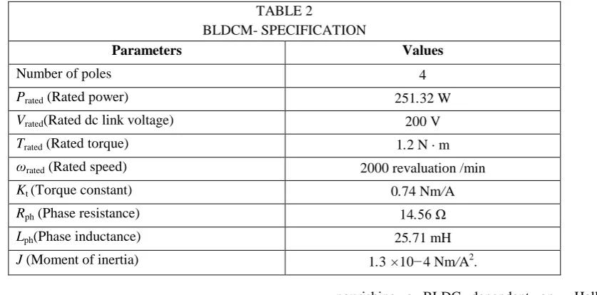
TABLE 2
BLDCM- SPECIFICATION
Parameters Values
Number of poles 4
Prated (Rated power) 251.32 W
Vrated(Rated dc link voltage) 200 V
Trated (Rated torque) 1.2 N · m
ωrated (Rated speed) 2000 revaluation /min
Kt (Torque constant) 0.74 Nm/A
Rph (Phase resistance) 14.56 Ω
Lph(Phase inductance) 25.71 mH
J (Moment of inertia) 1.3 ×10⁻⁴ Nm/A2
[image:3.595.81.518.61.349.2] [image:3.595.98.517.459.666.2][12] where switches (Sone– Ssix) are the exchanging conditions of the voltage source inverter converted by "one" or "zero" for the "on" and "off" places of the switch, separately. Table 2 explores the specification of our newly planned BLDCM.
IV. ANFC SYSTEM
From ANFC highlighted in Figure 3 & 4, it has been seen that when the estimations of parameters are fixed, the by and large output can be communicated as a direct mixture of the consequent parameters. Composite study evaluation is a mix of both back proliferation and the lower square calculations. Hybrid learning algorithm Comprises of two passes, to be specific forward pass and in reverse pass. In the forward go of the half and backward pass calculation, useful signs go ahead up to layer 4 and the ensuing parameters are distinguished by the least squares gauge. The back spread is utilized to distinguish the nonlinear parameters (premise parameters) and the least square is utilized for the straight parameters in the ensuing parts.
Fig.3 ANFIS Architecture
Fig.4 ANFIS Structure
Take a sugeno type of fuzzy system having the rule based.
If the triggering weights of the rule are 𝑤1& 𝑤2
correspondingly, for the finicky values of 𝐴𝑖 and integral of 𝐵𝑖 ,then the output is predicted as weighted average,
Let us think the membership purpose of fuzzy sets are, 𝐵𝑖 , i=1,2, be 𝜇𝐴𝑖 & 𝜇𝐵𝑖 .
First Layer: Every neuron in layer one is adaptive through a particular commencement task and its output is the position of membership purpose,
Wherever [ a, b, c] is the parameter set. As the standards of the parameters alteration, the shape of the bell-shape occupation varies.
Second Layer: All nodes are considered as a stable node, whose output of circuit is the result of all incoming signals.
Third Layer: This layer normalizes each input with respect to the others.
Fourth Layer: In this layer ith node output of both third & fourth layer is a linear function of adaptive neuro fuzzy input signals.
Fifth Layer: This layer adding of all the incoming signals.
Fig.5 Fundamental FLC Integrated BLDC .
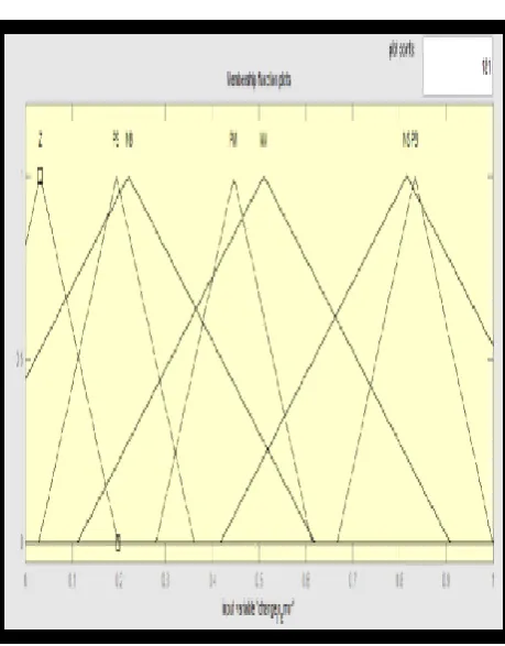
Fig.6 Membership Parameters of Fuzzy.
[image:5.595.45.546.545.744.2]Fig.8 Surface Viewer of T-S fuzzy logic.
[image:6.595.47.259.50.205.2]Fig.5 and 6 explores Fuzzification and defuzzification of fuzzy generation. Fig. 7 demonstrates the MATLAB recreation chart of FLC. The fuzzy deduction activity is executed by utilizing the 49 rules.
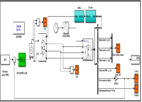
Fig.8 reveals the simulation outline of future sensor based speed control of BLDC.
V.SIMULATION RESULTS AND DISCUSSION The PID controller and Adaptive neuro fuzzy system were established to govern the speed of drive while sudden implement and exit of force as depicted in Fig. 9and 10. At a same time two different phases get simulated due to switch ON/OFF position, two out of six switches in upper and bottom leg of VSI which is initiated by decoder circuit. Outcome from VSI transferred to electric motor such as, rotor speed and electromagnetic torque and three phase stator currents with respect to time are taken out for calculations. Outputs of BLDCM are feed to Decoder circuit so it chooses the pulse of VSI. The real time work done with dissimilar working nature including sudden load application and removal in motor system.
[image:6.595.48.518.280.619.2]Fig.10 BLDC live model with ANFIS- PID In this characteristics curve, we project three different
cases viz., No load, sudden load, sudden removal of load with respect to three phase stator current, rotor speed, electromagnetic torque along with time variations.
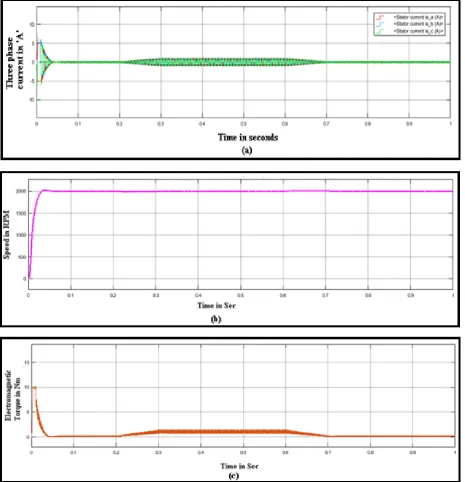
The BLDC electric motor is running freely in the duration t=0 to t=0.2 seconds. In this period, the curves show the constant speed, null torque and three phase stator current with respect to time.
The load torque of 3 Nm is applied suddenly during t=0.2 to t=0.7 seconds. In this region, the curve clearly shows a jerk during t=0.2 to t=0.3 seconds to attain a load torque of 3 Nm from null torque. Also from t=0.3 seconds it remains as 3 Nm up to t=0.7 seconds.
The load is removed suddenly during t=0.7 to t=1 seconds. From the graph it is clear torque become nullify in this period.
Load variations of BLDC electric Motor a. PID Controller
The finalized PID gains are Kp=0.013, Ki=16 and Kd=0.0001 through trial and error method.
(i) Starting characteristics of BLDCM (General
PID)
Fig.11 point outs the starting performance when abrupt load application for velocity variation of drive through earlier PID. The BLDC electric motor
speed becomes reference speed such as 2000 rpm while staring of the drive. During motor starting condition (from t=0 sec to t=0.2sec) torque rises for a second, after that small moment starting torque become null. At initial period of motor, the electric drive is act as a no load; the BLDCM parameter such as overshoot value is 5.58%, rise level is 0.017429 sec, settling limit is 0.018015 sec and peak point is 0.0203 sec.
(ii) Sudden implement and exit of force in
BLDCM
Fig-11: Characteristics of BLDCM when abrupt appliance of load and removal of load using general PID controller (a) Three phase current characteristics (b) Speed characteristics (c) Electromagnetic Torque characteristics.
b. ANFIS Controller
The present work focus the governing of speed in BLDC electric drive in efficient manner through ANFS to highlighien nonlinear position in low power applications such as refrigerator, blowers and airconditioner etc. The advantage of using ANFIS
instead single neural network,it is good in fuzzy expect system and using this, it is easy to identify and minimize the errors. The components used in this simulations are speed comparator to
compare the reference and actual rotor speed of motor, ANFIS controller to control the errors, voltage source inverter is for to convert the AC to DC and it works based on the switching control by electronic
Fig,12 Characteristics of BLDCM when abrupt appliance of load and removal of load using adaptive neuro controller (a) Three phase current characteristics (b) Speed characteristics (c) Electromagnetic Torque characteristics.
The presentation of two different cases arrived from the graph shown in figure 12 & 13, its appliance of load and removal of load with respect to speed and
electromagnetic torque using general PID controller and our proposed Adaptive neuro fuzzy-PID controller.
TABLE 3
Sudden
Load
Variation
Load
Charact
eristics
Actua
l
Speed
(rpm)
Time
Period
in
second
s
Peak
Time
in
second
s
Rising
Time in
seconds
Settling Time
in seconds
Overshoot
in
percentag
e (%)
General
PID
Controller
Starting
2000
0 to 0.2
sec
0.0203
0.017429
0.018015
5.58
0
Loading
2002
0.2 to
0.6 sec
0.0068
Nil
0.0175
-3.27
2
Load
Removal
2000
0.6 to
1.0 sec
0.0061
0.0172
3.27
0
Proposed
ANFIS
Controller
Starting
2000
0 to 0.2
sec
0.029
0.006025
0.0096
1.79
0
Loading
2000
0.2 to
0.6 sec
0.0059
Nil
0.0065
-2.56
0
Load
Removal
2000
0.6 to
1.0 sec
0.006
0.0089
2.59
0
VI. SPEED –TORQUE CHARACTERISTICS OF BLDC ELECTRIC MOTOR WHEN SUDDEN LOAD
FUNCTION
Fig.13 Speed - Torque Characteristics of BLDCM when abrupt appliance of load using general PID controller
Fig.14 Speed - Torque Characteristics of BLDCM when abrupt appliance of load using Adaptive Neuro Controller.
Among the two controllers, ANFIS – PID controller gives the efficient performance than former PID controller. The
PID controller. So, through ANC we obtained better initial performance in drive.
Among both the controllers, during sudden load submission as well as load removal, we get better values such as lower rising time, lower settling time and minimum steady state error in adaptive neuro controller shown in table-3.
VII. CONCLUSION
Simulation model was developed and performance were analyzed using PID and ANFC controllers when sudden load is applied and removed in drive at constant speed. In this circumstance, we got better performance while using ANFC – PID controller in such a way that getting good peak time, settling time, overshoot and undershoot than general PID controller. Also, the general arising problem jerk in BLDC electric motor during load applies and load removal also drastically reduced while using adaptive neuro fuzzy controller. Speed – toque characteristics were done for both the cases, from this also we identified ANFC gives overall efficient result than general PID controller.
REFERENCES
1. J. S. Mayer and O. Wasynczuk, “Analysis and modeling of a single phase brushless dc motor drive system,”, IEEE Trans. Energy Convers., vol. 4, no. 3, pp. 473–479, Sep. 1989.
2. C. Cossar, L. Kelly, T. J. E. Miller, C. Whitley, C. Maxwell, and D. Moorhouse, “The design of a switched reluctance drive for aircraft flight control surface actuation”, in Proc. IEE Colloq. Elect. Mach. Syst. More Elect. Aircraft, 1999, pp. 2/1–2/8.
3. R. Krishnan, D. Blanding, A. Bhanot, A.M. Staley, and N. S. Lobo, “High reliability SRM drive system for aerospace applications”, in Conf. Rec. IEEE IECON, 2003, vol. 2, pp. 1110–1115.
4. A. G. Jack, B. C. Mecrow, and J. A. Haylock, “A comparative study of permanent magnet and switched reluctance motors for high-performance fault-tolerant applications”, IEEE Trans. Ind. Appl., vol. 32, no. 4, pp. 889–895, Jul./Aug. 1996.
5. Lakshmi Mohan, “Comparison of PI and Adaptive Fuzzy PID Controllers for Speed Control of BLDC Motor”, International Journal of Innovative Research In Electrical, Electronics, Instrumentation And Control Engineering Vol. 2, Issue 2, February 2014.
6. Swapna.S ,Siddappa Naidu.K, “Characteristic Analysis of PFC using DC-DC Boost Converter Fed BLDCM”, International Journal of Innovative Technology and Exploring Engineering (IJITEE), Volume-8 Issue-7, May, 2019.
7. Swapna.S ,Siddappa Naidu.K, “Speed Characteristics of Brushless DC Motor Using Adaptive Neuro Fuzzy PID Controller under Different Load Condition”, International Journal of Innovative Technology and Exploring Engineering (IJITEE), Volume-7, Issue-5S3, February 2019.
8. Shamseldin MA, El-samahy AA. “Speed control of BLDC motor by using PID control and self-tuning fuzzy PID controller”, 15th int
work res educ mechatron 2014.
9. Thamizmani S, Narasimman S, “Design of fuzzy PID controller for brushless DC motor”, Int J Emerg Res Manage Technol 2014;9359:66–75.
13. Devendra Potnurua,, Alice Mary K, Saibabu Ch, “Design and implementation methodology for rapid control prototyping of closed loop speed control for BLDC motor”, Journal of Electrical Systems and Information Technology 5 (2018) 99–111.