THE STUDY ON THE EFFECTS OF CUTTING
PARAMETERS IN NEAR END CUTTING SPEED NORMAL
RANGE MACHINING
ZARIAH BINTI ZAINUDIN
UNIVERSITI TEKNIKAL MALAYSIA MELAKA
THE STUDY ON THE EFFECTS OF CUTTING PARAMETERS IN
NEAR END CUTTING SPEED NORMAL RANGE MACHINING
This report submitted in accordance with requirement of the Universiti Teknikal Malaysia Melaka (UTeM) for the Bachelor Degree of Manufacturing Engineering
(Manufacturing Process) with Honours.
by
ZARIAH BINTI ZAINUDIN
UTeM Library (Pind.1/2009)
UNIVERSITI TEKNIKAL MALAYSIA MELAKA
BORANG PENGESAHAN STATUS LAPORAN PSM
JUDUL: THE STUDY ON THE EFFECTS OF CUTTING PARAMETERS IN NEAR END CUTTING SPEED NORMAL RANGE MACHINING
SESI PENGAJIAN: Semester 2 (2008/2009)
Saya ZARIAH BINTI ZAINUDIN
mengaku membenarkan laporan PSM / tesis (Sarjana/Doktor Falsafah) ini disimpan di Perpustakaan Universiti Teknikal Malaysia Melaka (UTeM) dengan syarat-syarat kegunaan seperti berikut:
1. Laporan PSM / tesis adalah hak milik Universiti Teknikal Malaysia Melaka dan
penulis.
2. Perpustakaan Universiti Teknikal Malaysia Melaka dibenarkan membuat salinan
untuk tujuan pengajian sahaja dengan izin penulis.
3. Perpustakaan dibenarkan membuat salinan laporan PSM / tesis ini sebagai bahan
pertukaran antara institusi pengajian tinggi.
4. *Sila tandakan (√)
SULIT
TERHAD
TIDAK TERHAD
(Mengandungi maklumat yang berdarjah keselamatan atau
kepentingan Malaysia yang termaktub di dalam AKTA RAHSIA RASMI 1972)
(Mengandungi maklumat TERHAD yang telah ditentukan oleh organisasi/badan di mana penyelidikan dijalankan)
(TANDATANGAN PENULIS)
Alamat Tetap: Lot 281, Kg Kuau,
16300, Bachok, Kelantan Darul Naim
Tarikh: 16/04/2009
(TANDATANGAN PENYELIA)
Cop Rasmi:
Tarikh: _______________________
FAKULTI KEJURUTERAAN PEMBUATAN
Rujukan Kami (Our Ref) : 11 Mei 2009 Rujukan Tuan (Your Ref):
Pustakawan
Perpustakaan Universiti Teknikal Malaysia Melaka (UTeM) Taman Tasik Utama, Hang Tuah Jaya,
Ayer Keroh, 75450, Melaka
Saudara,
PENGKELASAN LAPORAN PSM SEBAGAI SULIT/TERHAD
- LAPORAN PSM SARJANA MUDA KEJURUTERAAN PEMBUATAN (PROCES PEMBUATAN): ZARIAH BINTI ZAINUDIN
TAJUK: THE STUDY ON THE EFFECTS OF CUTTING PARAMETERS IN NEAR END CUTTING SPEED NORMAL RANGE MACHINING
Sukacita dimaklumkan bahawa tesis yang tersebut di atas bertajuk “THE STUDY ON THE EFFECTS OF CUTTING PARAMETERS IN NEAR END CUTTING SPEED NORMAL RANGE MACHINING” mohon dikelaskan sebagai terhad untuk tempoh lima (5) tahun dari tarikh surat ini memandangkan ia mempunyai nilai dan potensi untuk dikomersialkan di masa hadapan.
Sekian dimaklumkan. Terima kasih.
“BERKHIDMAT UNTUK NEGARA KERANA ALLAH”
Yang benar,
……….. EN.MOHAMMAD KAMIL BIN SUED Pensyarah,
Fakulti Kejuruteraan Pembuatan
Universiti Teknikal Malaysia Melaka(UTeM) Karung berkunci 1200, Ayer Keroh,
75450, Melaka 06-2333454
UNIVERSITI TEKNIKAL MALAYSIA MELAKA Karung Berkunci 1200, Ayer Keroh, 75450 Melaka
DECLARATION
I hereby, declared this report entitled “THE STUDY ON THE EFFECTS OF CUTTING
PARAMETERS IN NEAR END CUTTING SPEED NORMAL RANGE MACHINING” is
the result of my own research except as cited in references.
Signature : ………
Author’s Name : ….ZARIAH BINTI ZAINUDIN……...
APPROVAL
This report is submitted to the Faculty of Manufacturing Engineering of UTeM as a partial fulfillment of the requirements for the degree of Bachelor of Manufacturing Engineering (Manufacturing Process) with Honours. The member of the supervisory committee is as follow:
(Signature of Supervisor)
i
ABSTRACT
ii
ABSTRAK
iii
DEDICATION
iv
ACKNOWLEDGEMENT
This project and the writing of this report has been a culmination for my studies in Universiti Teknikal Malaysia Melaka (UTeM). Many challengers have been faced during this project but at the same time it has been very interesting and rewarding.
Now that I am finishing this project, I would like to express my gratitude especially to
my supervisor, Mr. Muhammad Kamil bin Sued, for his constructive comments, ideas,
support and guidance throughout this project.
Besides that, I would like to say my gratefulness to the technicians of CNC laboratory, Mr Fauzi and Mr Jaafar which had given the advice when handling the machine and to provide the material and cutting tool needed for the machining operation.
v
TABLE OF CONTENT
ABSTRACT i
ABSTRAK ii
DEDICATION iii
ACKNOWLEDGEMENT iv
TABLE OF CONTENT v
LIST OF TABLES viii
LIST OF FIGURES ix
LIST OF ABBREVIATIONS x
1. INTRODUCTION 1
1.1 Introduction 1
1.2 Problem Statement 3
1.3 Objectives of the Project 4
1.4 Scope of the Project 4
2. LITERATURE REVIEW 5
2.1 High Speed Machining 8
2.2 Cutting Parameters 9
2.3 Aluminum 11
2.4 Surface Texture 13
2.5 Surface Roughness 14
2.6 Cutting Tools 16
2.6.1 Coated Carbide 16
2.6.2 Sintered Carbide/Cemented Carbide 17
2.6.3 Common Tool Coated Material 18
2.6.4 Multilayer Coated 19
2.7 Cutting tools Geometry 20
vi
2.8.1 Flank wear 22
3. DESIGN OF EXPERIMENT 25
3.1 Design of Experiment (DOE) 25
3.2 Taguchi Method 26
3.3 Orthogonal array 27
3.4 Analysis Signal to noise ratio 27
3.5 Experiment Technique 28
3.5.1 Define the Problem 28
3.5.2 Objective 29
3.5.3 The control factors and their level were identified. 29
3.5.4 The appropriate Orthogonal Array (OA) was selected. 29
3.5.5 Analyzing experiment data 30
4. METHODOLOGY 33
4.1 Machine 33
4.2 Workpiece 34
4.3 Cutting tool 34
4.4 Tool holder 36
4.5 Cutting parameters 36
4.6 Measurement equipment 38
4.6.1 Portable Surface Roughness Tester 38
4.6.2 Visual inspection station 39
4.7 Experiment Setup 40
4.8 Flow chart of the project 41
5. RESULT AND DISCUSSION 42
5.1 Surface Roughness 44
5.1.1 Discussion on Surface roughness 47
5.2 Flank wear 50
vii
5.2.2 Cutting Speed Influence the Tool Performance 55
5.2.3 TiN Coated and Multilayer Coated Influence the Tool Performance 54
5.3 Relationship between Surface Roughness and Flank Wear 56
6. CONCLUSION AND RECOMMENDATION 59
6.1 Conclusion 59
6.2 Recommendation 60
REFERENCES 62
APPENDIXES
A CNC turning machine
B Portable Surface Roughness Tester
C Visual inspection station
viii
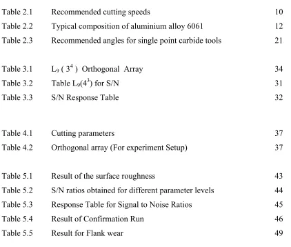
LIST OF TABLES
Table 2.1 Recommended cutting speeds 10
Table 2.2 Typical composition of aluminium alloy 6061 12
Table 2.3 Recommended angles for single point carbide tools 21
Table 3.1 L9 ( 34 ) Orthogonal Array 34
Table 3.2 Table L9(43) for S/N 31
Table 3.3 S/N Response Table 32
Table 4.1 Cutting parameters 37
Table 4.2 Orthogonal array (For experiment Setup) 37
Table 5.1 Result of the surface roughness 43
Table 5.2 S/N ratios obtained for different parameter levels 44
Table 5.3 Response Table for Signal to Noise Ratios 45
Table 5.4 Result of Confirmation Run 46
[image:14.612.111.533.130.488.2]ix
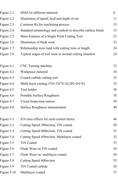
[image:15.612.114.526.103.726.2]LIST OF FIGURES
Figure 2.1 HSM for different material 8
Figure 2.2 Illustration of speed, feed and depth of cut 11
Figure 2.3 Common Ra for machining process 15
Figure 2.4 Standard terminology and symbols to describe surface finish 15
Figure 2.5 Main Features of a Single Point Cutting Tool 21
Figure 2.6 Illustration of flank wear 23
Figure 2.7 Relationship wear land with cutting time or length 24
Figure 2.8 Typical stages of tool wear in normal cutting situation 24
Figure 4.1 CNC Turning machine 33
Figure 4.2 Workpiece material 34
Figure 4.3 Coated carbide cutting tool 35
Figure 4.4 Multi-layer coating (TiN-TiCN-AL203-ZrCN) 35
Figure 4.5 Tool holder 36
Figure 4.6 Portable Surface Roughness 38
Figure 4.7 Visual Inspection station 39
Figure 4.8 Surface Roughness measurement 40
Figure 5.1 S/N ratio effects for each control factor. 46
Figure 5.2 Cutting Speed 300m/min, TiN coated 50
Figure 5.3 Cutting Speed 600m/min, TiN coated 51
Figure 5.4 Cutting Speed 450m/min, Multilayer coated 52
Figure 5.5 TiN Coated 53
Figure 5.6 Flank Wear on TiN coated 54
Figure 5.7 Flank Wear on multilayer coated 54
Figure 5.8 Cutting Speed 600m/min 55
Figure 5.9 TiN Coated carbide 56
x
LIST OF ABBREVIATIONS
AA - Arithmetic Average
AlCrN - Aluminium Chromium Nitrade
CLA - Center Line Average
CNC - Computer Numerical Control
CVD - Chemical Vapor Deposition
DOC - Depth of Cut
DOE - Design of Experiment
HSM - High Speed Machining
HSS - High Speed Steel
MRR - Material Removal Rate
PVD Physical Vapor Deposition
Ra - Average Roughness
RPM - Rotation Per Minutes
S/N - Signal Noise
TiC - Titanium Carbide
TiN - Titanium Nitrite
1
CHAPTER 1
INTRODUCTION
1.1 Background
Among the most effective and efficient modern manufacturing technologies, high speed machining (HSM) is employed to increase the productivity while simultaneously improving product quality and reducing manufacturing costs. High speed machining allows higher productivity, excellent surface finish and good dimensional accuracy in the manufacturing process. Therefore this technology has considerable advantages over traditional machining technologies (Canter, 2007).
2
In high cutting speed, surface roughness is one of the important factor for evaluating workpiece quality because the quality of surface roughness affects the functional characteristics of the workpiece such as compatibility, fatigue resistance and surface friction. Surface roughness is mainly affected from the process parameters such as tool geometry and cutting parameters. For tool geometry there are nose radius, edge geometry and rake angle and for cutting parameters there are feed rate, depth of cut and cutting speed. Roughnesses are obtained from the measurement on the surface of the workpieces. The quantification is done by the vertical deviations of a real surface from its ideal form. If these deviations are large, the surface is rough and if the deviations are small the surface is smooth. The deviations considered to be represented by the surface roughness (Ra) unit which it in high frequency with short wavelength. The roughness takes the average of the peaks and valleys over a given length during measurement. There are two methods assessing surface roughness either by contact or noncontact method.
3
strength of the tool is reduced as well as its capacity to conduct heat. In machining hard work materials, the back rake angle must be small, even negative for carbide and diamond tools.
During machining, cutting tool remove material from the component to achieve the required shape, dimension on surface roughness. However wear occurs during the cutting action, it will ultimately results in the failure of the cutting tool. When the tool wear reached a certain extent, the tool or active edge has to be replaced to guarantee the desired cutting action. Tool life of the cutting tool determined by the amount of wear that has occurred on the tool profile which reduces the efficiency of cutting to an acceptable level, or eventually causes tool failure. Tool life is affected by many variable related to the material used, the machining variable, and the machining conditions. The cutting speed, feed, depth of cut, tool material, tool form, condition of the machine and the condition under which the tool engages and disengages from the work are some material variables that effects the tool life. Some condition of the temperature of the work and tool, the ability of the system to dissipate heat the chip geometry, the forces required to remove chip and the feet rate (Lin, 2008).
1.2 Problem Statement
4
1.3 Objectives of the Project
The objectives of this study are:
a) To determine the effects of cutting parameters on the surface roughness at near end normal cutting speed range machining.
b) To study the effects of coated and multilayer coated on surface roughness. c) To study the tool performance of uses cutting tools.
d) To propose the suitable cutting parameters at near end normal cutting speed that able to produce smooth surface roughness.
1.4 Scope of the Project
5
CHAPTER 2
LITERATURE REVIEW
In the year of 2008, Ahmed presents a methodology for selecting optimal machining process parameters to obtain the required surface roughness. A carbide tool is used to machine a commercial aluminium workpiece on an AmcoTurn120P CNC lathe without any coolant. The speed used is 600 rpm, 800 rpm and 1000 rpm. The feed rate used is 80,120 and 160 mm/min. The depth of cut use is 0.25, 0.5, 1.0 mm. The best result produced when used speed of 1000rpm, feed rate at 80m/min and depth of cut of 0.25mm. The surface finish obtained from the setting is 0.40µm and where the surface roughness is 0.63µm. In this paper, it is showed that at higher speed, smaller feed would smooth the surface (Ahmed, 2006).
In 1979, McGee in his work with aluminium note that the tool chip interface temperature increased with cutting speed up to a maximum which is equal to the melting point of the workpiece. The plot curve did not show a decline in temperature as Salomon suggested. Rather it increased approaching the melting range of aluminium. The rating range fall much below the maximum temperature that most present day tool material can be with stand. This explains why aluminium is an ideal candidate for ultra high speed machining. The maximum cutting speed in the machining of aluminium is imposed by machine tool technology (McGee, 1978).
6
while the tool geometry is kept constant during the experiments. The experimental results showed that by increasing the cutting velocity from 120 m/min to 600 m/min, the cutting forces as well as the specific cutting energies are decreased by about 53 % of their values. The surface finish is also improved tremendously by that increase in cutting velocity (El Chazly, 1996).
Dr. Sinan Badrawy, Principal Engineer Cincinnati Machine, A UNOVA Company, do a research on Cutting dynamics of High Speed Machining. For Dr. Badrawy who has conducted extensive research in dynamic vibration analysis, it’s all in the chips. The material used is aluminium. Aluminium is one of the easiest metals to cut, which makes machining it a competitive challenge to the industry. Higher spindle speeds and machine feed rate, combined with a greater depth of cut, increases the metal removal rate and productivity. As a result, the manufacturer of aluminum parts faces not only limitations of the machine and tool, but also the dynamic characteristic of the spindle, toolholder and tool system. Under these conditions, the top spindle speed may not be the best speed for achieving the highest productivity. The maximum spindle speed is usually a good starting point. Chip load doesn’t strongly influence chatter. Any reasonable value will do during testing so long as the same chip load is used for every cut. The radial depth of cut can be picked arbitrarily. For the axial depth of cut, start light and keep increasing, cut after cut, until chatter sets in. there will be some spindle speeds at which it’s possible to perform much deeper cuts without chatter. Armed with these data, programmers can know what spindle speed and maximum depth of cuts to specify for which combination of machine, toolholder and cutting tool (Badrawy, 2001).
7
insert, the tool life takes high values even for high values of cutting speed. Tool life is defined using wear criterion value, which depends on cutting speed. The investigation included the realization of wear model in relation to the time. Also, empirical model have been developed for tool life determination in connection with cutting speed. On the basis of obtained results, it is possible to set optimal conditions to achieve the maximum tool life (Bauzid, 2005).
8
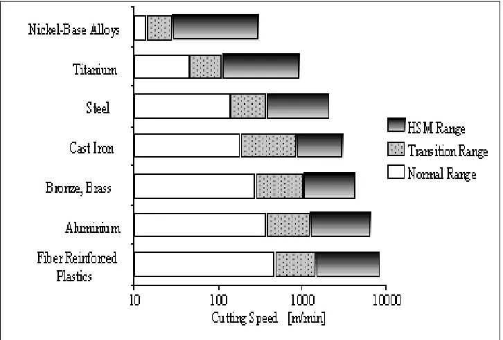
2.1 High Speed of Machining
[image:24.612.153.516.196.442.2]High-speed machining may be defined in various ways. High of cutting speed regards to attainable cutting speeds, it is suggested that operating at cutting speeds significantly higher than those typically utilized for a particular material may be termed in Figure 2.1.
Figure 2.1: HSM for different material (Schulz, 1992).
The term high in HSM is somewhat relatives as a general guide an approximate range of cutting speed may be defined as follows (Kalpakjian and shmid, 2006):
a. 30.5 m/min : Low speed conventional industrial machining b. 30.5-610m/min : Conventional industrial machining
c. 610 – 1830 m/min : High speed machining d. 1830 -18300 m/min : Very high speed machining