Joint Iterative Decoding of
Trellis-Based VQ and TCM
R. G. Maunder, J. Kliewer, S. X. Ng, J. Wang, L-L. Yang, and L. Hanzo
Abstract— A joint video and channel coded system employing an iteratively decoded serial concatenation of a Vector Quanti-zation (VQ) based video codec and a Trellis-Coded Modulation (TCM) scheme is proposed. The video codec imposes VQ-induced code constraints, which may be completely described by a trellis structure, which is employed as the basis for optimal minimum mean-squared-error VQ-encoding and -decoding. In the latter case, the Bahl-Cocke-Jelinek-Raviv (BCJR) algorithm is employed to facilitate the iterative exchange of soft informa-tion between the VQ and TCM decoder. An error-free video reconstruction quality is supported using 16-level Quadrature Amplitude Modulation (16QAM) based TCM for transmission over Rayleigh-fading channels at a Signal-to-Noise Ratio (SNR) per bit of 5.25 dB. This value is within 1.29 dB of the Rayleigh channel’s capacity at our system’s effective bandwidth-efficiency of 2 bits/s/Hz. Owing to its ability to exploit the VQ-induced code constraints during iterative decoding, the joint video and channel coding approach is found to consistently outperform the Shannonian source and channel separation philosophy. This is achieved at the cost of a 1.6 times higher computational complexity. Finally, the convergence of the iterative decoder is investigated with the aid of a novel so-called EXtrinsic Information Transfer (EXIT) chart.
Index Terms— Video coding, vector quantization, joint source and channel coding, trellis codes, BCJR.
I. INTRODUCTION
S
HANNON’S source and channel separation theorem [1] states that under certain idealized conditions, source and channel coding can be performed in isolation without any loss in performance. This motivated the designs of the Vector Quantization (VQ) based [2] video transmission system in [3] and the MPEG4-based [4] system of [5]. However, Shannon’s findings only apply under a number of idealistic assumptions. These assumptions have limited validity for practical video transmission systems communicating over realistic mobile-radio channels [2]. This motivates the application of joint source and channel coding techniques in wireless video trans-mission, as exemplified by [6].Let us now summarise the novelty of this paper in con-trast to the state-of-the-art. In [6], joint source and channel coding techniques were applied at the bit-level to mitigate channel-induced distortion within an MPEG-4 [4] coded video sequence. More specifically, knowledge of the residual cor-relation of bits within the MPEG-4 bitstream was exploited to assist their recovery upon reception. In our approach, joint
Manuscript received May 3, 2005; revised July 5, 2006; accepted October 22, 2005. The associate editor coordinating the review of this paper and approving it for publication was Q. Zhang. The financial support of the EP-SRC, Swindon UK, the EU under the auspices of the NEWCOM, NEXWAY and Phoenix projects and the Leverhulme Trust, London UK is gratefully acknowledged.
The authors are with the School of ECS, University of Southampton, SO17 1BJ, UK (e-mail: [email protected]).
Digital Object Identifier 10.1109/TWC.2007.05278.
source and channel coding techniques are applied at the Video Block (VB)-level within a specially designed novel proprietary video codec, which offers the advantage of directly assisting the recovery of the transmitted video information, rather than of its intermediate bit-based representation.
The design of the proposed video transmission system ex-tends the serial concatenation and iterative decoding proposals of [7], in a manner similar to that of [8]. More explicitly, a novel trellis-decoded VQ-based video codec is serially concatenated with the separate In-phase, Quadrature-phase (IQ) interleaved TCM codec of [9]. In the receiver, VQ- and TCM-decoding are performed iteratively.
The video codec of the proposed VQ-TCM system is designed to maintain a simple VQ-based transmission frame structure. The rules governing the formation of the legitimate bit-sequences of a transmission frame are referred to as the
VQ-induced code constraints in this contribution. The video codec was specifically designed to impose VQ-induced code constraints that may be completely described by a novel VQ trellis structure, reminiscent of the symbol-level trellis structure of [10]. This is in contrast to the video transmission systems of [3] and [5], in which the code constraints imposed by the video codec did not lend themselves to a trellis-based description.
As we will outline in Section III-D, the employment of the proposed VQ trellis structure represents the consideration of all legitimate transmission frame permutations. More ex-plicitly, we perform optimal Minimum Mean-Squared-Error (MMSE) VQ encoding of the video sequence in a novel manner that is reminiscent of Trellis-Coded Quantisation (TCQ) [11]. Additionally, the employment of the proposed VQ trellis structure during VQ decoding guarantees the recovery of legitimate – although not necessarily error-free – video infor-mation. Hence, unlike in the video transmission systems of [3] and [5], the proposed video decoder is never forced to discard information. During VQ decoding, a novel modification of the Bahl-Cocke-Jelinek-Raviv (BCJR) [12] algorithm provided in [13] is performed on the basis of the proposed VQ trellis structure. This allows the exploitation of the VQ-induced code constraints to assist in joint iterative VQ- and TCM-decoding. Additionally, this allows the unconventional softA Posteriori
Probability (APP) based [14] MMSE reconstruction of the transmitted video frames.
This paper is organised as follows. In Section II, the pro-posed VQ-TCM system is introduced. Section III describes the TCM system’s transmission frame structure and the VQ-induced code constraints. Additionally, the complete descrip-tion of the VQ-induced code constraints by the proposed VQ trellis structure is discussed in Section III. The employment of the VQ trellis structure in VQ-encoding and -decoding is
TCM encoder
x π
fn
− +
Reconstruction buffer
e1 eM
ˆ e1 eˆM
u1
uM
u MVQ
encoders
ˆ fn
+
e
ˆ e ˆfn − 1
[image:2.567.37.266.53.144.2]+
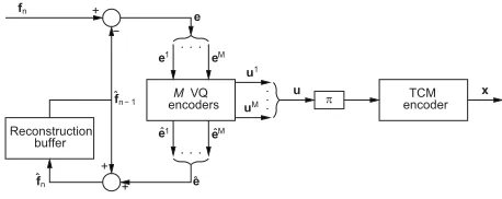
Fig. 1. The proposed VQ-TCM system’s transmitter.
described in Sections IV and V, respectively. In Section VI, both low- and high-latency implementations of the proposed VQ-TCM system are introduced and their video reconstruction quality is assessed. Finally, the performance of the proposed joint video and channel coding approach is compared to that of the video transmission systems of [3] and [5]. Our conclusions are offered in Section VII.
II. SYSTEMOVERVIEW
In this section we introduce the proposed VQ-TCM video transmission system, which employs a joint video and channel coding philosophy, as introduced in Section I. The video codec of this system achieves compression by employing low-complexity frame differencing and VQ of the resultant Frame Difference (FD) [2]. These are chosen in favour of the more advanced but higher complexity compression techniques, such as sub-pixel-accuracy MPEG4-style Motion Compensation (MC) or the Discrete Cosine-Transform (DCT) [2]. This en-sures that a simple transmission frame structure is maintained, as we will detail in Section III. Rather than performing an excessive-complexity single VQ-encoding or -decoding operation for the entire video frame as usual, a decomposi-tion into a number of smaller VQ operadecomposi-tions is performed. This approach is associated with a significant computational complexity reduction, as will be shown in Section III-D. The proposed video codec is protected by the serially concatenated TCM codec of [9] and joint iterative decoding is employed in the receiver. These issues are further detailed in the following sub-sections with reference to the proposed VQ-TCM system’s transmitter and receiver schematics seen in Figures 1 and 2, respectively.
A. Compression
In the VQ-TCM system’s transmitter of Figure 1, the previous reconstructed video frame ˆfn−1 is employed as a prediction for the current video frame fn. The FD e =
fn−ˆfn−1 has a lower variance than the current video frame
fn. Hence, the transmission of the FDeto convey the current video framefn provides compression.
As will be discussed in Section III, VQ is employed to represent the FDein a compact bit-sequence form, namely the transmission frameu. Hence, the VQ offers compression. This compression is termed ‘lossy’ because the VQ approximates the FD e by the reconstructed FD ˆe, as shown in Figure 1. The reconstructed FD ˆe is employed to obtain the current reconstructed video frameˆfn=ˆe+ˆfn−1, which is stored for the sake of providing the prediction of the next video frame.
π
L2
a(u1) L2a(uM)
L2
p(u1) L2p(uM)
π−1
L2 e(u)
(1) y
Reconstruction buffer ˜fn − 1
L1
a(u) =L2e(u) L2p(u) =L1e(u) +L2e(u)
L1 e(u)
+ −
+ −
+ ˜fn
+ ˜e ˜e1
˜eM
L2 a(u) =L1e(u)
(2) decoderTCM decodersMVQ L1
[image:2.567.292.540.54.146.2]p(u) =L2e(u) +L1e(u)
Fig. 2. The proposed VQ-TCM system’s receiver.
B. Vector quantization decomposition
In the proposed VQ-TCM system’s transmitter and receiver, VQ-encoding and -decoding are performed, respectively. As will be detailed in Sections III-A and III-D, we decompose each FDeintoM number of smaller sub-frames, which may be represented by VQs operating in parallel. This decompo-sition implies the corresponding decompodecompo-sition of both the reconstructed FDˆeand the transmission frameu, as indicated by the braces{and}in Figure 1. In the transmitter,Mnumber of separate VQ operations are employed. Each VQ encoder approximates the FD sub-frame em by the reconstructed FD sub-frame ˆem, where m ∈ [1. . . M] denotes the sub-frame index. Additionally, the transmission sub-sub-frame um is generated, as will be detailed in Section IV. The bit-based transmission frame u is constituted by the concatenation of the set of theseM number of transmission sub-frames.
C. Serial concatenation and iterative decoding
In the proposed VQ-TCM system, the video codec is serially concatenated with the TCM codec of [9]. In the transmitter, the current video frame fn is conveyed by the reconstructed FD ˆe, where the latter is generated using VQ encoding and is represented by the transmission frame u, as discussed in Section II-A. The transmission frame u is interleaved in the block π of Figure 1 and TCM encoded to generate the channel’s input symbolsx. These are transmitted over the channel and are received as the channel’s output symbols y, as shown in Figure 2. Finally, TCM- and VQ-decoding are employed to recover the reconstructed FD esti-mate ˜e. This allows the recovery of the current video frame estimate˜fn=˜e+˜fn−1, as shown in Figure 2.
In the receiver, Soft-In Soft-Out (SISO) TCM- and VQ-decoding are performed iteratively, as shown in Figure 2. Soft information, represented in the form of Logarithmic Likelihood-Ratios (LLRs) [14], is exchanged between the TCM and VQ iterative decoding stages for the sake of as-sisting each other’s operation. With each successive decoding iteration, the reliability of this soft information increases, until iterative decoding convergence is achieved. In Figure 2,L(·) denotes the LLRs of the specified bits, where the superscript
(1) denotes TCM decoding and(2) represents VQ decoding. Additionally, a subscript denotes the role of the LLRs, with a, p and e indicating a priori, a posteriori and extrinsic information, respectively.
During each decoding iteration, a priori LLRs La(u) are provided for each iterative decoding stage, as shown in Fig-ure 2. Naturally, in the case of TCM decoding, the channel’s output symbols y are also exploited. Note that the a priori
Macro-block grouping boundaries. Each macro-block group comprises
M= 3 3 macro-blocks. 1
2 3 4
5 678 9
10 11 12
Video block, comprising (8×8) pixels.
Macro-block, comprising
JMB= 4 video blocks.
FD sub-frame,comprising
J= 1 2 video blocks. FD, comprising
M⋅J= 396 video blocks.
Fig. 3. Example of selectingJ= 12 (8×8)-pixel VBs from a(176×144) -pixel FD to provide one of theM= 33FD sub-frames.
the other decoding stage, as will be highlighted below. In the case of the first decoding iteration no previous VQ decoding has been performed. In this case, the a priori LLRs L1a(u) provided for TCM decoding are all zero, corresponding to a probability of 0.5 for both ‘0’ and ‘1’. Each iterative decoding stage applies the BCJR [12] algorithm, as described in [9] and Section V for TCM- and VQ-decoding, respectively. The result is the generation of the a posterioriLLRs Lp(u), as shown in Figure 2.
During iterative decoding, it is necessary to prevent the re-use of already-exploited information, since this would limit the attainable iteration gain [15]. This is achieved following each decoding stage by the subtraction ofLa(u)fromLp(u), as shown in Figure 2. Following VQ decoding, we arrive at the extrinsic LLRsL2e(u). In the case of TCM decoding, the LLRsL1e(u) additionally contain information extracted from the channel’s output symbolsy. It is these sets of LLRs that provide the a priori LLRs for the next iteration of the other decoding stage. De-interleaving, indicated by the blockπ−1 in Figure 2, is applied toL1e(u) in order to generateL2a(u). Similarly, interleaving is applied to L2e(u) for the sake of providing L1a(u), as shown in Figure 2. These interleaving and de-interleaving operations are necessary for the sake of mitigating the correlation of consecutive LLRs, before forwarding them to the next iterative decoding stage [14]. As always, the interleaver’s ability to provide this desirable statistical independence is related to its length.
As stated in Section II-B, M number of separate VQ decoding processes are employed in the proposed VQ-TCM system’s receiver. Similarly to the decomposition of the bit-based transmission frame u, the a priori LLRs L2a(u) are decomposed into M number of sub-frames, as shown in Figure 2. This decomposition is accompanied by the corre-sponding decomposition of thea posterioriLLRsL2p(u)and the reconstructed FD estimate˜e. Each VQ decoder is provided with thea priori LLR sub-frame L2a(um)and generates the a posterioriLLR sub-frame L2p(um), wherem ∈ [1. . . M]. Additionally, each of theM number of VQ decoding process recovers the reconstructed FD sub-frame estimate˜em, as will be detailed in Section V.
III. TRANSMISSIONFRAMESTRUCTURE
As stated in Section II, each video frame fn is conveyed between the proposed VQ-TCM system’s transmitter and receiver by means of a single bit-based transmission frame
V Q1 4 , V Q1
3 , , V Q1
1V Q 1 2
{ } V Q2,
1V Q 2 2} {
VQ1 VQ2
VQ3 VQ4 VQ5
} V Q3
1 {V Q41}{V Q51} {
k
Index Video blocks
(Jk
x×Jyk) = Jk Bits Ik RVLC code RVLCk VQ tiles: Video block, comprising (8×8) pixels.
1 1
2 3 4 5
(2×2) = 4 0
2 3 4 5 11 101 1001 10001
(1×2) = 2
(1×1) = 1
(1×1) = 1
[image:3.567.317.511.50.251.2](1×1) = 1
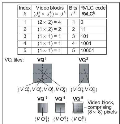
Fig. 4. Example of aK= 5-entry VQ codebook.
Macro-block, comprising
JMB= 4 video blocks.
Ta 5 1 5
1 1 1
IkT
JkT
kT T Tb Tc Td Te Tf 4 3 3 1 1 4 3 3 1 1 4 4 ˆ e
m=2
VQ
4 1
ˆ
e
m=3
VQ
3 1
ˆ
e
m=6
VQ 1 3 ˆ e m 10 = VQ 1 3 ˆ e m 11 = VQ 1 2 ˆ e m 12 = VQ 1 1 ˆem=
ˆ
e
m=8
VQ
1 1
} 1,0,0,0,1,1,0,0,1,1,0,1,1,0,1,0,0
um= {
ˆ
e
m=5
VQ
1 4
ˆ
e
m=1
VQ
5 1
ˆ
e
m=4
VQ
3 1
ˆ
e
m=7
VQ
1 2
ˆ
e
m=9
VQ
1 4
[image:3.567.28.279.54.186.2]Ta Tb Tc Td Te Tf
Fig. 5. Example of a reconstructed FD sub-frame, comprising J = 12 VBs selected as exemplified in the FD decomposition of Figure 3, and the correspondingI= 17-bit transmission sub-frame. These comprise the entries
kT, whereT∈[Ta. . . Tf], from the VQ codebook example of Figure 4.
u. This comprises the concatenation of M number of VQ-based transmission sub-frames. Again, the formation of legit-imate bit-sequences within these transmission sub-frames is governed by simple VQ-induced code constraints, which are imposed by the decomposition of FDs into sub-frames and by the specific nature of the VQ codebook to be outlined in Section III-B. These VQ-induced code constraints may be described by a novel VQ trellis structure. These issues are discussed in the following sub-sections and are described with the aid of an example that continues throughout Figures 3, 4, 5 and 6. It should be noted that the generalization of this example is straightforward.
A. Frame difference decomposition
[image:3.567.294.539.285.403.2]¨ j j
en(ˆem 11)
Ta
Tb
Tc
Td
Te
to(S(16,8))
4 7 10 11 12 15
1 2 3 4 5 6 7 8 9 10 11 12 13 14 15 16 17
0 1 2 3 5 6 8 9 13 14 16 17
4 5 6 7 8 9 10 11 12
3 4 5 6 7 8 9 10 12 11
1 2 3
0 1 2
¨ı fr(S(2,2))
S(2,2)
i en(um
7)
S(16,8)
Tf
Transmission sub-frame, comprisingI= 17 bits
FD
sub-frame,
comprising
J
=
12
VBs
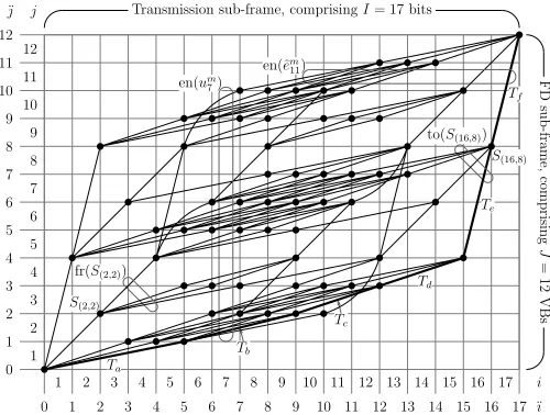
Fig. 6. Example of a VQ trellis structure for the FD decomposition example of Figure 3 and for theK= 5-entry VQ codebook example of Figure 4, where we haveJ= 12andI= 17. Trellis states occur between the consideration of specific bits and VBs, hence bit state indices¨ıand VB state indices¨joccur between the bit indicesiand the VB indicesj, respectively.
The proposed video codec operates on a block-based phi-losophy. In this contribution, a video block (VB) has the dimensions of (8×8) pixels and is defined as the smallest unit of video information that is considered in isolation. Each of theM number of FD sub-framesem comprises a unique combination ofJ number of (8×8)-pixel VBs of the FD e. Hence, the FD e comprises M ·J number of VBs in total. In the example of Figure 3, each of the M = 33 FD sub-frames in the(176×144)-pixel FD comprisesJ = 12of the M·J = 396 (8×8)-pixel VBs, which are shown with dashed boundaries.
We proceed by decomposing the FDeinto a set of perfectly tilingmacro-blocks (MBs). Each MB has the dimensions of
(JMB
x ×JyMB) = JMB number of VBs, where J = 12 is an integer multiple of JMB. In the example of Figure 3, MBs are shown with solid boundaries and have the dimensions of (JxMB ×JyMB) = (2×2) VBs, giving JMB = 4. The MBs are then assigned toJ/JMB= 3different groups on the basis of the distance between their centre and the FD centre, with each group comprising M = 33 MBs. This results in J/JMB= 3quasi-concentric MB groups, as indicated by the thick boundaries in Figure 3. A pseudo-random selection of one MB from each of the J/JMB = 3groups is performed for each FD sub-frameem. It is theJ= 12 (8×8)-pixel VBs identified by this pseudo-random MB selection that constitute the FD sub-frame em. We note that a pre-determined fixed seed is employed for the sake of allowing identical pseudo-random MB selections to be made independently by both the video encoder and decoder.
Each of theJ = 12 (8×8)-pixel VBsemj , that constitute the FD sub-frame em = {emj }Jj=1, is allocated a VB index j∈[1. . . J]. TheseJ = 12VB indices are allocatedamongst
the J/JMB = 3 pseudo-randomly selected MBs in a quasi-radial ordering. In this way, theJMB = 4 lowest-valued VB indices are allocated to the MB nearest to the FD centre, as seen in Figure 3. Similarly, the MB nearest to the FD perimeter is assigned the JMB = 4 highest-valued VB indices. The allocation of VB indices within MBs should be made with
specific consideration of the VQ codebook employed, as will be detailed in Section III-C. Again, Figure 3 exemplifies the indices allocated to theJ = 12VBs of a FD sub-frame.
As mentioned, the FD sub-frames have statistical properties that are similar to each other, however it should be noted that each of theJ/JMB= 3 constituent MBs is likely to exhibit different statistical properties. For example, the MB that is allocated the lowest-valued VB indices in each FD sub-frame can be expected to exhibit a high level of video activity, since this MB is located near the centre of the FD. By contrast, a low level of video activity can be expected for the MB that is assigned the highest-valued VB indices.
The reconstructed FD sub-frameˆem ={ˆemj }Jj=1 employs the same VB selection and indexing as the corresponding FD sub-frame em = {emj }Jj=1. The same applies to the
reconstructed FD sub-frame estimate˜em={˜emj }Jj=1.
In contrast to the FD decomposition described above, an alternative approach could comprise a selection of J = 12 adjacentVBs for each FD sub-frame. Although this alternative would permit the exploitation of correlation between adjacent VBs, each FD sub-frame would have different statistical properties. As a result, the corresponding transmission sub-frames would require different individual bit-allocations on a demand-basis. Additionally, each transmission sub-frame’s different bit-allocation would require a separate VQ-encoder and -decoder design. Finally, the transmission of side in-formation would be required for the sake of signalling this allocation between the transmitter and the receiver. Hence, this alternative approach was discarded for the sake of maintaining simplicity.
B. VQ codebook
As stated in Section II, each FD sub-frameem is approxi-mated by the reconstructed FD sub-frameˆemand represented by the bit-based transmission sub-frame um on the basis of the same VQ codebook. This comprises K number of VQ tiles addressed by their Reversible Variable-Length Coding (RVLC) based [16] codebook index. These are known to both the video encoder and decoder. An example of aK= 5-entry VQ codebook is provided in Figure 4. In the VQ tiles of this figure, dark pixels indicate negative FD values and light pixels represent positive FD values.
As exemplified in Figure 4, the K number of VQ tiles in the VQ codebook may have different dimensions, which must be multiples of the(8×8)-pixel VB dimensions. This allows the adequate representation of both small areas of high video activity and large areas of low video activity. In this way, coding efficiency is maintained. The VQ codebook entry with index k ∈ [1. . . K] is associated with the VQ tile VQk. This has the dimensions of (Jxk ×Jyk) = Jk number of (8×8)-pixel VBs, as exemplified in Figure 4. However, a VQ tile’s dimensions must not exceed the MB dimensions of (JxMB×JyMB) = (2×2) VBs, as defined in Section III-A. Each VB V Qkjk, from the set of Jk VBs that constitute
the VQ tile VQk = {V Qkjk}J k
[image:4.567.28.278.52.241.2]Additionally, the VQ codebook entry indexkis represented by the RVLC code RVLCk, as exemplified in Figure 4. Each RVLC codeRVLCk ={RV LCikk}I
k
ik=1 comprisesIk
number of bits having values ofRV LCikk ∈ {0,1}, whereik∈ [1. . . Ik] is the bit index. The employment of RVLC codes instead of their more efficient, higher coding-rate alternatives, such as Huffman codes [17], will be justified in Section III-C. The VQ codebook should be designed by considering the statistical properties of the FD sub-frames. This can be achieved by employing the Linde-Buzo-Gray algorithm [18] to design the VQ tile set and a Huffman coding based algorithm [16] to design the RVLC code set.
Recall from Section III-A that all FD sub-frames exhibit similar statistical properties, but different statistical properties are exhibited by each of theJ/JMB= 3 MBs that constitute the FD sub-frames. In an alternative approach, a separate VQ codebook could be designed and employed to model the statistical properties of each of these MBs. This alternative approach would allow the achievement of a higher coding efficiency. However, it was discarded for the sake of simplicity.
C. VQ-induced code constraints
Let us now elaborate on how the employment of VQ im-poses code constraints that govern the formation of legitimate bit-sequences within the transmission sub-frames. In Figure 5 an example of a VQ-based J = 12-block reconstructed FD sub-frame ˆem is provided. Here, we employed the FD decomposition example of Figure 3 and theK= 5-entry VQ codebook example of Figure 4. The correspondingI= 17-bit transmission sub-frameumis subject to the VQ-induced code constraints outlined below.
As stated in Section III-A, each reconstructed FD sub-frameˆem ={ˆemj }Jj=1 comprisesJ = 12 (8×8)-pixel VBs.
These J = 12 VBs constitute J/JMB = 3 MBs, as shown in Figure 5. Each of these MBs comprises an appropriate tessellation of VQ tiles from theK-entry VQ codebook. The tilesVQk={V Qkjk}J
k
jk=1may cover regions of(Jxk×Jyk) = Jk number of(8×8)-pixel VBs. Note that, in Figure 5 each of the entries kT, where T ∈ [Ta. . . Tf], invoked from the VQ codebook example of Figure 4 providesJkT number of
(8×8)-pixel VBs for the reconstructed FD sub-frameˆem. A specific constraint is imposed that restricts the positioning of the tile VQk in legitimate tessellations. Specifically, the Jk number of VBs inˆem={eˆmj }Jj=1that are represented by
the tileVQk must have consecutive VB indices j. Note that this is true in all cases in Figure 5. This VQ tile positioning constraint is imposed to allow the formation of the novel trellis structure to be described in Section III-D. In order that the video-degradation imposed by this constraint is minimised, the VQ tiles and the allocation of VB indices within the MBs should be jointly designed, as stated in Section III-A. In view of this, the presence of the vertical VQ tileVQ2 in the VQ codebook example of Figure 4 motivates the vertical allocation of consecutive VB indices within each MB, as seen in Figure 3.
The employment of the VQ tileVQkis expressed usingJk number of mappings of the formeˆmj =V Qkjk, as exemplified
in Figure 5. With reference to the examples of Figures 3 and 4, we note that the resultant values of j ∈ [1. . . J] and
jk ∈[1. . . Jk]in such mappings are dependent on the specific positioning of the VQ tile.
Each of the VQ tilesVQk that comprise the reconstructed FD sub-frameˆemis associated with an RVLC codeRVLCk, wherek is the VQ codebook entry index. These RVLC codes are concatenated in the order of the VB indices j that are associated with the employment of the corresponding VQ tiles in the reconstructed FD sub-frame ˆem = {eˆmj }Jj=1. This is
exemplified in Figure 5, in which each of the entrieskT, where T ∈ [Ta. . . Tf], invoked from the VQ codebook example of Figure 4 is represented byIkT number of bits. In the proposed video codec this concatenation is constrained to having a total length of I = 17 bits, since it constitutes the I = 17-bit transmission sub-frameum.
It follows from the above discussions that eachI= 17-bit transmission sub-frame must represent a legitimate tessellation of VQ tiles, comprising J = 12 VBs in total. These VQ-induced code constraints represent redundancy within the bit-based transmission sub-frames. Note that the degree of this redundancy is dependent on the distance properties of the RVLC code set employed. As will be outlined in Section VI, the employment of RVLC codes rather than Huffman codes is justified, because their additional redundancy is desirable.
D. VQ trellis structure
As described in Section III-C, the formation of legitimate bit-sequences within each of the bit-based transmission sub-frames is governed by the VQ-induced code constraints. During VQ-encoding and -decoding we consider only legit-imate I= 17-bit transmission sub-frame permutations. Since satisfying this constraint is non-trivial, the employment of a trellis structure is proposed to describe the complete set of VQ-induced code constraints. These VQ-VQ-induced code constraints depend on the FD decomposition and the VQ codebook employed, as described in Section III-C. Hence, the design of the proposed VQ trellis structure also depends on these aspects of the proposed video codec’s operation. The VQ trellis structure example of Figure 6 describes the complete set of VQ-induced code constraints that correspond to the FD decomposition example of Figure 3 and to the K = 5 -entry VQ codebook example of Figure 4. In this example, each reconstructed FD sub-frameˆem comprisesJ = 12VBs and each transmission sub-frameum comprisesI= 17bits.
The proposed VQ trellis structure comprises a set of tran-sitions between trellis states, as exemplified in Figure 6. A novel block-based modification of the Variable Length Coding (VLC) symbol-level trellis structure described in [10] is employed. Whilst the bit index axis of [10] is retained in the proposed VQ trellis structure, the VLC symbol index axis of [10] is replaced by a VB index axis. In contrast to [10], transitions are permitted to skip a number of consecutive indices along this axis.
T represents a possible employment of the VQ codebook entry having the index kT ∈ [1. . . K]. This is associated with a unique combination of(a) the positioning of the VQ tile VQkT within the reconstructed FD sub-frameˆem and
(b) the corresponding positioning of the associated RVLC codeRVLCkT within the transmission sub-frameum. Note that for reasons to be discussed below,(a) is subject to the legitimate VQ tile positioning constraint that was stated in Section III-C.
Each trellis stateS(¨ı,¨j) in the proposed VQ trellis structure
represents the progress made at a particular point during the VQ-encoding or -decoding operation. This point occurs immediately after the consideration of the first ¨j number of VBs in the reconstructed FD sub-frame ˆem and the first ¨ı number of bits in the transmission sub-frameum. Here, ¨j∈ [0. . . J] denotes a VB state index. These occur between the VB indicesj∈[1. . . J]that were introduced in Section III-A. Likewise, bit state indices¨ı∈[0. . . I] occur between the bit indicesi∈[1. . . I], as shown in Figure 6.
Each transition T represents the employment of the VQ codebook entry with index kT ∈ [1. . . K] immediately af-ter reaching a particular point during the VQ-encoding or -decoding operation. This point is identified by the state indices¨ıT ∈ [0. . . I] and ¨jT ∈ [0. . . J]. Hence, the transi-tion T emerges from the trellis state S(¨ıT,j¨T). The VQ tile VQkT
provides JkT number of VBs for the reconstructed FD sub-frameˆem, as stated in Section III-C. Additionally, the RVLC code RVLCkT provides IkT number of bits for the transmission sub-frameum. Hence, the transition T merges into the trellis stateS(¨ıT+JkT,¨jT+IkT). Note that the VQ tile
positioning constraint described in Section III-C is necessary to ensure that each transition is continuous with respect to the VB index axis. Also note that a particular employment of a VQ codebook entry is only possible if the associated transition T contributes to a legitimate transition path between the trellis statesS(0,0) andS(I,J). This condition is satisfied if at least
one transition path exists between the trellis statesS(0,0) and S(¨ıT,j¨T) and between the trellis states S(¨ıT+IkT,j¨T+JkT) and S(I,J).
Note that the reconstructed FD sub-frame and transmission sub-frame examples of Figure 5 correspond to the bold trellis path in Figure 6. Here, each transition T ∈ [Ta. . . Tf] corresponds to the similarly labelled employment of a VQ codebook entry in Figure 5. With reference to Figure 5, observe that each transitionT ∈[Ta. . . Tf]encompassesIkT number of bit indices andJkT number of VQ indices. Whilst the trellis path considered comprises six transitions, it should be noted that the trellis structure of Figure 6 additionally contains trellis paths comprising seven transitions. In general, each transition path in the proposed VQ trellis structure comprises a varying number of transitions.
Note furthermore that a single VQ trellis structure consid-eringJ·M = 396VBs andI·M = 561 bits would contain more transitions than the combination ofM = 33VQ trellis structures, each consideringJ = 12VBs andI= 17bits. This justifies the decomposition of the VQ-encoding and -decoding operations of an entire FD into M = 33 less complex trellis-based VQ operations, as described in Section II-B. This decomposition is associated with a reduced grade of VQ
encoding freedom and hence a reduced video reconstruction quality. However, this slight video degradation is insignificant compared to the resultant computational complexity reduction. For the benefit of the following sections, we now introduce some trellis-transition set notation, which is exemplified in Figure 6. The set of all transitions that encompasses (en) the VB j ∈ [1. . . J] of the reconstructed FD sub-frame ˆem is termeden(ˆemj ). Furthermore,en(ˆemj =V Qkjk)is the specific
sub-set of en(ˆemj ) that maps the VB jk ∈ [1. . . Jk] of the VQ tileVQk ontoeˆmj . Note that some of these sub-sets may be empty. This is a consequence of the VQ tile positioning constraint described in Section III-C. The set of all transitions that encompasses the biti∈[1. . . I]of the transmission sub-frame um is termed en(umi ). Additionally, en(umi = b) is the specific sub-set of en(umi ) that maps the bit value b ∈ {0,1} onto umi . Note that for a particular transition T, we have RV LCik−T¨ıT =b if T ∈en(umi =b). Finally, the set of
transitions emerging from (fr) the trellis stateS(¨ı,¨j)is denoted
as fr(S(¨ı,¨j)), whilst the set merging into (to) that trellis state
is represented asto(S(¨ı,¨j)).
IV. VQ ENCODING
In the proposed VQ-TCM system’s transmitter of Figure 1, VQ encoding is performed separately for each of theM num-ber of FD sub-frames. Each VQ encoder operates on the basis of the proposed VQ trellis structure described in Section III-D and exemplified in Figure 6. Since it describes the complete set of VQ-induced code constraints, the employment of the proposed VQ trellis structure represents the consideration of every legitimate FD sub-frame encoding. This allows us to find the MMSE approximation of the FD sub-frameem. The result is the optimal reconstructed FD sub-frameˆem and the corresponding bit-based transmission sub-frameum.
We quantize the video sequence in a novel manner, which is reminiscent of TCQ [11], but considers the tessellation of potentially differently sized VQ tiles. The philosophy of Viterbi decoding [15] is employed, with a survivor path being selected at each trellis state S(¨ı,j¨). This selection yields the ¨ı-bit encoding of the first j¨number of VBs in the FD sub-frameemthat introduces the lowest possible cumulative video distortionD(S(¨ı,¨j)).
As stated in Section III-D, each transitionT in the proposed VQ trellis structure represents the employment of the VQ codebook entry with index kT during VQ encoding. This corresponds to employing the VQ tile VQkT to represent a total of JkT number of (8×8)-pixel VBs of the FD sub-frame em. The distortiond(T)associated with the transition T is the sum of the squared difference between VQkT and the correspondingJkT number of VBs ofem.
The survivor path at the trellis state S(¨ı,j¨) is deemed to
be that associated with the specific merging transition T ∈ to(S(¨ı,¨j)) having the minimum cumulative video distortion. This is calculated as D(T) = d(T) + D(S(¨ıT,j¨T)), where D(S(0,0)) = 0. Having determined the survivor path at the
trellis state S(I,J), the MMSE VQ encoding of the FD
V. VQ DECODING
In the proposed VQ-TCM system’s receiver of Figure 2, VQ decoding is performed separately for each of theM number ofI-bit transmission sub-frames. Each of the M number of VQ decoders operates on the basis of the proposed VQ trellis structure. The recovery of legitimate – although not neces-sarily error-free – video information is therefore guaranteed, since the proposed VQ trellis structure describes the complete set of VQ-induced code constraints. As stated in Section III-C, these VQ-induced code constraints impose redundancy within each transmission sub-frame. This redundancy may be exploited to assist during VQ decoding by invoking the BCJR [12] algorithm on the basis of the proposed VQ trellis structure. Additionally, residual redundancy is exhibited by the transmission sub-frameumowing to the simplicity of the proposed video codec. This may be exploited by the BCJR algorithm with consideration of the statistical properties of FD sub-frames, as will be detailed below.
Each VQ decoder is provided with the a priori LLR sub-frameL2a(um)and generates thea posterioriLLR sub-frame L2p(um), as stated in Section II-C. Additionally, each VQ decoder recovers the optimal MMSE-based reconstructed FD sub-frame estimate˜em. This is achieved using soft APP-based reconstruction, as follows.
A novel block-based modification of the BCJR algorithm of [13] is invoked in the proposed VQ trellis structure. This obtains an APP for each transition, giving the probability that this specific transition was in the survivor path during the corresponding VQ encoding operation, as described in Section IV. These APPs are calculated as
P(T|y) = 1
C1·α(S(¨ıT,j¨T))·γ(T)·β(S(¨ıT+IkT,¨jT+JkT)). (1)
The specific value of the normalisation factor C1 = p(y)
in (1) may be ignored in this application, since we are only concerned with the ratios ofa posterioritransition probabili-ties, as we will show below. The termsα(S(¨ıT,j¨T)),γ(T)and β(S(¨ıT+IkT,¨jT+JkT))consider the probability of the requisite
trellis activity before, during and after the occurrence of the transitionT, respectively.
Specifically, the termγ(T)in (1) is calculated as
γ(T) = P(k T) C2(S(¨ıT,¨jT))·
IkT
ik=1
P(um¨ıT+ik=RV LCk T
ik |y), (2)
where P(umi = b|y) is the a priori probability that the transmission sub-frame bitumi has a value ofb∈ {0,1}. This is obtained from thea prioriLLR L2a(umi ) = ln(P(u
m i =0|y) P(um
i =1|y))
[14]. Furthermore,P(k)in (1) is the probability of occurrence for the VQ codebook entry with index k. This is obtained based on knowledge of the statistical properties of the FD sub-frames. As stated in Section III-A, different statistical properties are associated with each of theJ/JMB number of MBs constituting a FD sub-frame. Hence, different values of P(k) are employed, depending on the specific MB thatT is constituent of. Finally, the normalisation factor C2(S(¨ı,j¨)) =
T∈fr(S(¨ı,¨j))P(k
T) was proposed in [13] for the sake of ensuring that (2) represents a true probability.
The BCJR algorithm’s forward recursion emerging from the trellis stateS(0,0)is employed to obtain the values of
α(S(¨ı,¨j)) =
T∈to(S(¨ı,j¨))
γ(T)·α(S(¨ıT,¨jT)), (3)
where α(S(0,0)) = 1. Similarly, a backward recursion from
the trellis state S(I,J)is employed to obtain the values of β(S(¨ı,j¨)) =
T∈fr(S(¨ı,¨j))
γ(T)·β(S(¨ıT+IkT,¨jT+JkT)), (4)
whereβ(S(I,J)) = 1.
Having determined the a posterioritransition probabilities, the method of [13] is employed for obtaining bit-based soft outputs. This is facilitated by the employment of the normal-isation factorC2(S(¨ıT,j¨T))during the calculation ofγ(T), as
described above. For each of the I number of bits in the transmission sub-frameum={umi }Ii=1, we consider a cross-section of the trellis structure, which is perpendicular to the bit index axis at the particular indexi. The associateda posteriori
LLR is calculated as
L2p(umi ) = ln
T∈en(um
i =0)P(T|y)
T∈en(um
i =1)P(T|y)
. (5)
The recovery of the reconstructed FD sub-frame estimate
˜em is performed on an individual block-by-block basis. A soft APP-based output is obtained for each of the J number of (8×8)-pixel VBs in ˜em. Again, a novel modification of the method of [13] is employed for obtaining these block-based soft outputs. For each of the J number of VBs in the reconstructed FD sub-frame ˆem = {eˆmj }Jj=1, we consider a cross-section of the trellis structure. In analogy to the generation of the previously mentioned bit-based soft outputs, this cross-section is now perpendicular to the VB index axis at the particular indexj. The APP of the VBˆemj being provided by a particular one of the Jk number of VBs in the VQ tile
VQk={V Qk jk}J
k
jk=1 is calculated as
P(ˆemj =V Qkjk|y) =
T∈en(ˆem
j =V Qkjk)P(T|y)
T∈en(ˆem
j )P(T|y)
. (6)
Note that some of the sets en(ˆemj =V Qkjk) may be empty,
as described in Section III-D. In this case, the corresponding APP is zero-valued.
Each of theJ number of(8×8)-pixel VBs that constitute the reconstructed FD sub-frame estimate ˜em = {˜emj }Jj=1 is
obtained using optimal MMSE estimation according to
˜ emj =
K
k=1 Jk
jk=1
P(ˆemj =V Qkjk|y)·V Qkjk. (7)
0.0 0.1 0.2 0.3 0.4 0.5 0.6 0.7 0.8 0.9 1.0
I
A1
, I
E2
0.0 0.1 0.2 0.3 0.4 0.5 0.6 0.7 0.8 0.9 1.0
I
E 1,I
A
2
High latency Eb/N0= 6 dB
L ow latency Eb/N0= 6 dB
E X IT trajectory: Eb/N0= 11 dB
Eb/N0= 10 dB
Eb/N0= 9 dB
Eb/N0= 8 dB
Eb/N0= 7 dB
Eb/N0= 6 dB
Eb/N0= 5.25 dB
Eb/N0= 4 dB
[image:8.567.35.269.51.282.2]T CM E X IT characteristic: Inverted V Q E X IT characteristic
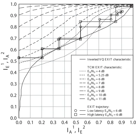
Fig. 7. The proposed VQ-TCM system’s EXIT chart for the ‘Lab’ video sequence and a3/4-rate TCM scheme.
where the transition paths passing through the trellis state S(¨ı,j¨)are pruned during the forward recursion if
α(S(¨ı,¨j)) I
¨ı=0α(S(¨ı,j¨)) <
0.001. (8)
In the next section we consider the performance of the proposed VQ-TCM system, where the above-mentioned complexity-reduction methods were observed to impose no significant performance degradation.
VI. RESULTS
In this section we assess the performance of the proposed VQ-TCM system. We transmitted 250 video frames of the ‘Lab’ video-sequence [2]. This 10 frames/s grey-scale head-and-shoulders(176×144)-pixel Quarter Common Intermedi-ate Format (QCIF) video sequence exhibits a moderIntermedi-ate level of video activity.
The proposed video codec was designed to achieve an attractive trade-off between the conflicting design require-ments associated with bitrate, video reconstruction quality and computational complexity. The 396-block FDs were de-composed into M = 33 FD sub-frames, each comprising J = 12 (8×8)-pixel VBs. This was performed exactly as exemplified in Figure 3. However, in contrast to our simplified example of Figure 6 usingI = 17 bits per sub-frame, each transmission sub-frame comprisedI = 45bits in the system implemented. AK= 512-entry VQ codebook was employed. This comprised the five VQ tiles shown in Figure 4 and an additional 507 single-VB VQ tiles. The corresponding RVLC codes were designed to have a minimum free distance of two [16]. The coding rate of the proposed video codec is defined here as the ratio of its entropy to its average RVLC code length. This may be estimated as the area beneath the inverted VQ decoding EXIT characteristic [14] provided in Figure 7, which will be discussed in more detail below. This gives a coding rate ofRV Q≈0.666.
Two VQ-TCM schemes associated with different latencies were employed. The first scheme imposed a low latency equal to the duration of a single video frame, namely 0.1 s at 10 frames/s. This is suitable for realtime interactive video-telephony applications. In this scheme the length of each transmission frame u and that of the interleaver π equals M ·I= 1485bits. The second VQ-TCM scheme had a high latency of 50 video frames, i.e. 5 s at 10 frames/s. This is suitable for non-realtime video streaming and wireless-Internet download applications. Here, 50 transmission frames u are concatenated before interleaving, giving an interleaver length of 50·M ·I = 74250bits. Note that both schemes have a video encoded bitrate of 14.85 kbps.
The same TCM codec was employed in both VQ-TCM schemes. This terminated RT CM = 3/4-rate TCM codec employed a coding memory of 6, MT CM = 16-level QAM modulation and IQ-interleaving [9] for transmission over an uncorrelated narrowband Rayleigh fading channel. The band-width efficiency of the proposed VQ-TCM system is given by η=RV Q×RT CM×log2(MT CM) = 2.00bit/s/Hz without a
Nyquist excess bandwidth. More explicitly, we assume ideal Nyquist filtering and ignore the code termination symbols added by the TCM encoder. Note that at η = 2 bit/s/Hz the uncorrelated Rayleigh-fading channel’s capacity limit for 16QAM is Eb/N0= 3.96dB [21], whereEb/N0=SN R/η
is the Signal to Noise Ratio (SNR) per bit.
Again, in Figure 7 we provide the EXIT characteristics [22] for TCM decoding at variousEb/N0values. These can be seen to achieve unity extrinsic mutual informationIE1 for unity a priorimutual informationIA1. Additionally, Figure 7 provides the inverted VQ decoding EXIT characteristic. Similarly to TCM decoding, VQ decoding achieves unity extrinsic mutual informationIE2 for unitya priorimutual informationIA2. This was found to be the benefit of the employment of an RVLC code set having a minimum free distance of two.
Additionally, Figure 7 provides EXIT trajectories [22] for both the low- and high-latency VQ-TCM schemes atEb/N0= 6 dB. The low-latency trajectory can be seen to deviate from the EXIT characteristics and fails to converge to the desired unity mutual information. By contrast, the high-latency trajec-tory closely matches these EXIT characteristics and converges to unity mutual information. The improved performance of the high-latency scheme is a benefit of its longer interleaver [14], justified by the reasons noted in Section II-C. Note that iterative decoding convergence to unity mutual information is associated with the achievement of an infinitesimally low video degradation. The proposed VQ-TCM system supports this for Eb/N0 ≥ 5.25 dB, as shown in Figure 7. With the
advent of a sufficiently long interleaver and of a sufficiently high number of decoding iterations, infinitesimally low video degradation could be achieved at Eb/N0 = 5.25 dB. This is just 1.29 dB from the proposed VQ-TCM system’s channel capacity limit of 3.96 dB.
In Figure 8, the video reconstruction quality of both the low- and high-latency VQ-TCM schemes is assessed after a number of decoding iterations and for a range of channel Eb/N0 values. We employ the Peak-Signal to Noise Ratio
4 5 6 7 8 9 10 11 12 Eb/N0[dB ]
24 26 28 30 32
Av
er
ag
e
P
S
N
R
[d
B
]
MPE G4-based bench-marker V Q-based bench-marker V Q-T CM low latency V Q-T CM high latency
8 iter 2 iter 1 iter
1.4 dB
[image:9.567.36.271.53.199.2]0.7 dB
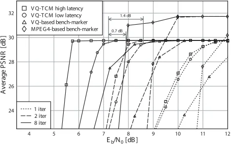
Fig. 8. PSNR performance of the proposed VQ-TCM system as well as of the VQ- and MPEG4-based bench-markers for the ‘Lab’ video sequence, when communicating over an uncorrelated narrowband Rayleigh fading channel.
The proposed VQ-TCM system exhibited substantial iteration gains, as shown in Figure 8. After eight decoding iterations an Eb/N0 iteration gain of 4.34 dB was achieved by the
low-latency scheme at a PSNR of 29.5 dB. In the case of the high-latency scheme, the corresponding iteration gain was 5.61 dB. The high-latency scheme was seen to outperform the low-latency scheme, regardless of the number of decoding iterations. This is in agreement with the findings of the EXIT chart analysis of Figure 7, as discussed above. For the low-latency scheme, a PSNR higher than 29.5 dB was achieved after eight decoding iterations forEb/N0>7.00dB, as shown in Figure 8. This is 3.04 dB from the proposed VQ-TCM system’s channel capacity limit of 3.96 dB. In the case of the high-latency scheme, this is achieved forEb/N0>5.75dB,
which is just 1.79 dB from the channel’s capacity limit. We now compare the performance of the proposed VQ-TCM system with two bench-markers. Similarly to the pro-posed VQ-TCM system, the IQ-TCM-VLC system of [3] is also VQ-based and is hence referred to as theVQ-based bench-markerhere. In contrast, the IQ-TCM-RVLC system of [5] is MPEG4-based and is referred to here as the MPEG4-based bench-marker. Similarly to the proposed VQ-TCM system, the bench-markers employ both RVLC and TCM. However, they adopt Shannon’s source and channel coding separation philosophy [1], with video decoding being performed inde-pendently of iterative RVLC- and TCM-decoding. Since the bench-markers have the same latency, coding rate and bitrate as the low-latency VQ-TCM scheme, their direct comparison is justified.
In Figure 8, the low-latency VQ-TCM scheme can be seen to outperform the VQ-based bench-marker, regardless of the number of decoding iterations. Although the MPEG4-based bench-marker achieves a slightly higher error-free video reconstruction quality than the proposed VQ-TCM system, it is outperformed by the scheme advocated at low values of Eb/N0. At a PSNR of 29.5 dB, the proposed VQ-TCM system offers a consistent improvement over both the VQ- and MPEG4-based bench-markers, which amounts to about 1.4 dB and 0.7 dB, respectively. This is a benefit of the iterative exploitation of the video codec’s code constraints, as outlined in Section V. Additionally, this approach guarantees the recov-ery of legitimate video information. Hence, the proposed VQ-TCM system is never forced to discard any video information.
By contrast, both the bench-markers of [3] and [5] drop video information, when the iterative decoding process does not recover legitimate video information, reducing the attainable video reconstruction quality.
The improved performance offered by the proposed VQ-TCM system is achieved at the cost of an increased compu-tational complexity. A simple metric of compucompu-tational com-plexity considers the number of BCJR trellis transitions en-countered during iterative decoding. Note that this ignores the complexity contribution imposed by trellis pruning and video reconstruction. Although an equal number of BCJR transitions are employed during TCM decoding in the proposed VQ-TCM system and in the bench-markers, the complexity of the respective VQ- and RVLC-decoding operations are different. More explicitly, in the proposed VQ-TCM system, VQ decod-ing employs a channel-condition-dependent number of BCJR transitions, which is typically equal to the number of trellis transitions encountered during TCM decoding. By contrast, RVLC decoding has approximately a quarter of the number of trellis transitions, in both bench-markers. Hence, the proposed VQ-TCM system has a computational complexity that may be deemed approximately 1.6 times that of the bench-markers.
VII. CONCLUSIONS
In this contribution we have considered the concept of joint video and channel coding. The proposed video codec imposed VQ-induced code constraints, which were described by a novel VQ trellis structure. This VQ trellis structure was the basis of the proposed MMSE VQ-encoding and -decoding processes. In the latter case, a novel BCJR algorithm was employed to facilitate the iterative exchange of soft information with the serially concatenated TCM decoder. The proposed VQ-TCM system was shown to support error-free video reconstruction at 1.29 dB from the Rayleigh-channel’s capacity limit of 3.96 dB.
The joint video and channel coding approach of the pro-posed VQ-TCM system was shown to consistently outperform two powerful bench-markers, both employing the Shannonian source and channel separation philosophy [1]. However, this performance improvement was found to accrue at the cost of a 1.6 times increase in computational complexity. Our further research will consider the application of the techniques introduced here to standard video codecs.
REFERENCES
[1] C. E. Shannon, “A Mathematical Theory of Communication,”The Bell System Technical Journal, vol. 27, no. 3, pp. 379–656, July 1948. [2] L. Hanzo, P. J. Cherriman, and J. Street, Wireless Video
Communica-tions: Second to Third Generation Systems and Beyond. New York, USA: IEEE Press, 2001.
[3] S. X. Ng et al., “Joint Iterative-Detection of Reversible Variable-Length Coded Constant Bit Rate Vector-Quantized Video and Coded Modulation,” inEuropean Signal Processing Conference (EUSIPCO), Vienna, Austria, Sept. 2004, pp. 2231–2234.
[4] Information Technology – Coding of Audio-Visual Objects – Part 2: Visual, ISO/IEC 14496-2:2004 Std.
[5] S. X. Ng et al., “A Turbo-Detection Aided Serially Concatenated MPEG-4/TCM Videophone Transceiver,” inIEEE Vehic. Technol. Conf. (VTC), Los Angeles, USA, Sept. 2004.
[7] S. Benedetto et al., “Serial Concatenation of Interleaved Codes: Per-formance Analysis, Design and Iterative Decoding,”IEEE Trans. Info. Theory, vol. 44, no. 3, pp. 909–926, May 1998.
[8] J. Hagenauer and N. G¨ortz, “The Turbo Principal in Joint Source-Channel Coding,” inProc. IEEE Info. Theory Wksp., Paris, France, Mar. 2003, pp. 275–278.
[9] S. X. Ng and L. Hanzo, “Space-Time IQ-Interleaved TCM and TTCM for AWGN and Rayleigh Fading Channels,” IEE Electronics Letters, vol. 38, pp. 1553–1555, Nov. 2002.
[10] R. Bauer and J. Hagenauer, “Symbol-by-Symbol MAP Decoding of Variable Length Codes,” in ITG Conference on Source and Channel Coding, Munich, Germany, Jan. 2000, pp. 111–116.
[11] M. W. Marcellin and T. R. Fischer, “Trellis Coded Quantization of Mem-oryless and Gauss-Markov Sources,” IEEE Trans. Commun., vol. 38, no. 1, pp. 82–93, Jan. 1990.
[12] L. R. Bahlet al., “Optimal Decoding of Linear Codes for Minimizing Symbol Error Rate,”IEEE Trans. Inform. Theory, vol. 20, pp. 284–287, Mar. 1974.
[13] J. Kliewer and R. Thobaben, “Iterative Joint Source-Channel Decoding of Variable-Length Codes Using Residual Source Redundancy,” IEEE Trans. Wireless Commun., vol. 4, no. 3, May 2005.
[14] J. Hagenauer, E. Offer, and L. Papke, “Iterative Decoding of Binary Block and Convolutional Codes,”IEEE Trans. Inform. Theory, vol. 42, no. 2, pp. 429–445, Mar. 1996.
[15] L. Hanzo, T. H. Liew, and B. L. Yeap,Turbo Coding, Turbo Equalisation and Space Time Coding for Transmission over Wireless Channels. Chichester, UK: Wiley, 2002.
[16] Y. Takishima, M. Wada, and H. Murakami, “Reversible Variable Length Codes,” IEEE Trans. Commun., vol. 43, no. 2/3/4, pp. 158–162, Feb./Mar./Apr. 1995.
[17] D. A. Huffman, “A Method for the Construction of Minimum-Redundancy Codes,” inProc. IRE, vol. 40, no. 9, pp. 1098–1101, 1951. [18] Y. Linde, A. Buzo, and R. Gray, “An Algorithm for Vector Quantizer Design,”IEEE Trans. Commun., vol. 28, no. 1, pp. 84–95, Jan. 1980. [19] P. Robertson, E. Villebrun, and P. Hoeher, “A Comparison of Optimal
and Sub-Optimal MAP Decoding Algorithms Operating in the Log Domain,” inIEEE Int’l. Conf. Commun., Seattle, USA, June 1995, pp. 1009–1013.
[20] V. Franz and J. B. Anderson, “Concatenated Decoding with a Reduced-Search BCJR Algorithm,”IEEE J. Select. Areas Commun., vol. 16, no. 2, pp. 186–195, Feb. 1998.
[21] L. Hanzoet al.,Quadrature Amplitude Modulation. Chichester, UK: Wiley, 2004.
[22] S. ten Brink, “Convergence Behaviour of Iteratively Decoded Parallel Concatenated Codes,”IEEE Trans. Commun., vol. 49, no. 10, pp. 1727– 1737, Oct. 2001.
Robert G. Maunderhas studied with the School of Electronics and Computer Science, University of Southampton, UK, since October 2000. He was awarded a first class honours BEng in Electronic Engineering in July 2003, shortly before beginning his current PhD studies in the Communications Research Group at the same university. His research interests include video coding, joint source/channel coding and iterative decoding.
J¨org Kliewer (S’97–M’99–SM’04) received the Dipl.-Ing. degree in Electrical Engineering from Hamburg University of Technology, Hamburg, Ger-many, in 1993 and the Dr.-Ing. degree (Ph.D.) in Electrical Engineering from the University of Kiel, Kiel, Germany, in 1998, respectively. From 1993 to 1998, he was a Research Assistant at the Institute for Circuits and Systems Theory at the University of Kiel, Germany. In 1996, he spent five months at the Image Processing Lab, University of California, Santa Barbara, CA, as a visiting researcher. Since 1999, he is with the Faculty of Engineering, University of Kiel, Germany, as a Senior Researcher and Lecturer. In 2004 he was visiting the University of Southampton, U.K., for one year, and since 2005 he is with the University of Notre Dame, IN, as a Visiting Assistant Professor. He was the recipient of a both Leverhulme fellowship award and a German Research Foundation fellowship award in 2003 and 2004, respectively. His current research interests include joint source and channel coding, error correcting codes, network information theory, and network coding
Soon Xin Ng (S’99-M’03) received the B.Eng. degree (First class) in electronics engineering and the Ph.D. degree in wireless communications from the University of Southampton, Southampton, U.K., in 1999 and 2002, respectively. From 2003 to 2006, he was a postdoctoral research fellow working on collaborative European research projects known as SCOUT, NEWCOM and PHOENIX. Since August 2006, he has been a lecturer in wireless communica-tions at the University of Southampton. His research interests are mainly in adaptive coded modulation, channel coding, space-time coding, joint source and channel coding, OFDM and MIMO. He has published numerous papers and coauthored a book in this field.
Jin Wang (S’03) received the B.E. degree from University of Science and Technology of China (USTC), Hefei, China in 1999 and the M.E. degree in video signal processing from Graduate School of Chinese Academy of Sciences (GSCAS), Beijing, China, in 2002.
He is currently pursuing his PhD degree with the Communications Re-search Group at the School of ECS, University of Southampton, Southampton, UK. His research interests include video coding, channel coding, joint source/channel coding, and iterative detection and decoding for digital com-munication systems.
Dr. Lie-Liang Yangreceived his B.Eng. degree in communication engineering from Shanghai TieDao University, Shanghai, China in 1988, and his M.Eng, Ph.D. degrees in communications and electronics from Northern Jiaotong University, Beijing, China in 1991 and 1997, respectively. From June 1997 to December 1997 he was a visiting scientist of the Institute of Radio Engineering and Electronics, Academy of Sciences of the Czech Republic. Since December 1997, he has been with the Communi-cations Research Group, School of Electronics and Computer Science, University of Southampton, U.K, where he was first a Postdoctoral Research Fellow (Dec. 1997 - Aug. 2002), then a Lecturer (Sept. 2002 - Feb. 2006), and currently holds the academic post of Readership.
Dr. Yang’s research has covered a wide range of areas in telecommuni-cations, which include error control coding, modulation and demodulation, spread-spectrum communications and multiuser detection, synchronization, space-time processing, adaptive wireless systems, as well as wideband, broadband and ultrawide-band code-division multiple-access (CDMA). He has published over 130 papers in journals and conference proceedings, coauthored one book and published several book chapters. He was awarded the Royal Society Sino-British Fellowship in 1997 and the EPSRC Research Fellowship in 1998. Dr. Yang is currently an associate editor for both theJournal of Communications and Networks (JCN) and theJournal of Communications
(JCM).