UNIVERSITI TEKNIKAL MALAYSIA MELAKA
ACCURACY STUDY OF CAR RIM ON FIVE-AXIS
SIMULTANEOUS MILLING AND NINE-AXIS TURN-MILL
MACHINE BY USING CATIA V5
This report submitted in accordance with requirement of the Universiti Teknikal Malaysia Melaka (UTeM) for the Bachelor’s Degree in Manufacturing Engineering
Technology (Process and Technology) with Honours.
by
LOK SOO KEE B071410299 941014-08-5258
UNIVERSITI TEKNIKAL MALAYSIA MELAKA
BORANG PENGESAHAN STATUS LAPORAN PROJEK SARJANA MUDA
TAJUK: ACCURACY STUDY OF CAR RIM ON FIVE-AXIS SIMULTANEOUS MILLING AND NINE-AXIS TURN-MILL MACHINE BY USING CATIA V5
SESI PENGAJIAN: 2017/28 SEMESTER 1
Saya LOK SOO KEE
mengaku membenarkan Laporan PSM ini disimpan di Perpustakaan Universiti Teknikal Malaysia Melaka (UTeM) dengan syarat-syarat kegunaan seperti berikut:
1. Laporan PSM adalah hak milik Universiti Teknikal Malaysia Melaka dan penulis. 2. Perpustakaan Universiti Teknikal Malaysia Melaka dibenarkan membuat salinan
untuk tujuan pengajian sahaja dengan izin penulis.
3. Perpustakaan dibenarkan membuat salinan laporan PSM ini sebagai bahan pertukaran antara institusi pengajian tinggi.
4. **Sila tandakan ( )
SULIT
TERHAD
TIDAK TERHAD
(Mengandungi maklumat yang berdarjah keselamatan atau kepentingan Malaysia sebagaimana yang termaktub dalam AKTA RAHSIA RASMI 1972)
(Mengandungi maklumat TERHAD yang telah ditentukan oleh organisasi/badan di mana penyelidikan dijalankan)
Alamat Tetap:
No 2216, Batu 10,
Kampung Jenderata, 36400 Hutan
Melintang, Perak,
Tarikh: ________________________
Disahkan oleh:
Cop Rasmi:
Tarikh: _______________________
DECLARATION
I hereby, declared this report entitled “ACCURACY STUDY OF CAR RIM ON FIVE-AXIS SIMULTANEOUS MILLING AND NINE-AXIS TURN-MILL MACHINE BY USING CATIA V5” is the results of my own research except as
cited in references.
Signature : ……….
Author’s Name : ………
APPROVAL
This report is submitted to the Faculty of Engineering Technology of UTeM as a partial fulfillment of the requirements for the degree of the Bachelor’s Degree in Manufacturing Engineering Technology (Process and Technology) with Honours. The member of the supervisory is as follow:
………
i
ABSTRAK
Pada masa kini, penggunaan CNC adalah sangat penting dalam industri perkilangan terutamanya bidang automotif, aeroangkasa dan pesawat. Penggunaan mesin CNC ini adalah untuk menghasilkan pelbagai produk yang berkualiti berbanding dengan proses operasi manual. Terdapat konfigurasi mesin CNC yang terdiri daripada berbeza system paksi dan pusat pemesinan. Apakah jenis mesin CNC yang dapat menghasilkan produk dengan lebih tepat? Tujuan kajian ini adalah untuk membandingkan ketepatan lima paksi serentak mesin CNC dan sembilan paksi mesin CNC. Cara simulasi telah digunakan untuk mengawal mesin CNC dalam proses pemesinan lanjutan CAM. CATIA V5 telah digunakan sebagai simulasi pemesinan perisian CAM untuk menghasilkan strategi pemotongan dengan penggunaan komputer sebagai proses simulasi pemotongan sebenar. Rekabentuk rim kereta BMW dihasilkan dengan penggunaan kedua-dua mesin CNC. 3D sanner digunakan sebagai alat pengukuran dimensi terhadap hasil pemesinan lalu menganalisis keputusan geometri. Hasil kajian ini adalah 5-paksi pergerakan mesin CNC yang lebih tepat dari segi ketepatan permukaan berbanding dengan sembilan paksi pergerakan mesin CNC. Tetapi dari segi masa pemesinan, sembilan paksi pergerakan mesin CNC lebih cepat daripada 5 paksi pergerakan mesin CNC. Terdapat beberapa perkara yang perlu diperbaiki untuk meningkatkan kebenaran hasil kajian ini ialah menambahbaik mesin setting, CAM setting dan analisis.
ii
ABSTRACT
Today, the application of CNC machine in manufacturing production are important especially automotive industry, aerospace industry, and aircraft industry. The usage of CNC machines in these all the fields were able produce the parts more accurate as compared to manually operations process. CNC machines consist various of configuration with the different type of axis system and machining center. The aims of this paper describe the comparison accuracy of the five-axis simultaneous CNC machine and nine-axis turn-mill CNC machine. CATIA V5 is used as CAM simulation advanced machining software to control CNC machine and compute the tool cutting path strategy as simulating the real cutting process. BMW car rim design machining by using these two CNC machines respectively. 3D scanner was chosen as the equipment for measuring the physical geometry dimensional accuracy of the machining parts. Then analysis process to the results of the geometry parts. The result of this study is in 5 axes simultaneous machine more accurate in surface accuracy as compare to nine-axis turn-mill CNC machine. However, in term of machining time turn-mill will be faster than 5-axis simultaneous milling machine. There were several things that needed to improve in result is the machine setting, parameter setting in CAM program and analysis software setting.
iii
DEDICATION
iv
ACKNOWLEDGEMENT
I want to give thanks to all the persons that have become a big part of this study. Firstly, I would like to thank our God for giving me the strength of finish this study.
To my beloved university, Universiti Teknikal Malsysia Melaka (UTeM) give me this opportunity to explore myself.
It is a greats pleasure to acknowledge my deepest thanks and gratitude to Mr. MUHAMMAD SYAFIK BIN JUMALI, for guiding and helping me in order to make the study well done achievement. It is a great honour to work under his supervision.
I would like to express my extreme sincere gratitude and appreciation to Mr. SYAHRUL AZWAN BIN SUNDI @ SUANDI for his kind endless help, generous and support during the study.
Otherwise, I would like to take this opportunity to express my deepest thanks to all assistance engineers in UTeM which given fully assistance for this research study.
v
TABLE OF CONTENT
ABSTRAK i
ABSTRACT ii
DEDICATION iii
ACKNOWLEDGEMENT iv
TABLE OF CONTENT v
LIST OF FIGURES viii
LIST OF TABLES x
LIST OF ABBREVIATIONS, SYMBOLS AND NOMENCLATURE xi
CHAPTER 1 INTRODUCTION 1
1.1 Background 1
1.2 Problem statement 4
1.3 Objective 5
1.4 Scope 6
CHAPTER 2 LITERATURE REVIEW 7
2.1 Five-axis simultaneous CNC machine 7
2.2 Nine-axis turn-mill CNC machine 9
2.3 Lead and tilt angles 13
2.4 Simulation method by using CATIA software 15
2.5 Accuracy 22
2.6 Characteristics of the Aluminum Alloys 26
CHAPTER 3 METHODOLOGY 29
vi
3.1.1 Flow chart for phase I 30
3.1.2 Flow chart for phase II 31
3.1.3 Gantt Chart 32
3.2 Research methodology 34
3.2.1 Identify machines types and configurations 34
3.2.2 Study literature review 34
3.2.3 Searching suitable CAD part model and analysis it 35 3.2.4 Analysis the part design and predetermine suitable machining process. 36 3.2.4.1 Cutting planning machining process for turn mill process. 38 3.2.4.2 Cutting planning for five-axis simultaneous milling process. 39 3.2.5 Stock and early stage before enter CAM programming 40
3.2.6 Five-axis simultaneous programming 42
3.2.6.1 Part operation setting 42
3.2.6.2 Tool inserts 44
3.2.6.3 Tool call 45
3.2.6.4 Machining process (Bottom) 47
3.2.6.6 Machining process (Wall part) 48
3.2.7 Turn-mill programming 52
3.2.7.1 Part operation setting 53
3.2.7.2 Tool inserts/ Tool call 57
3.2.7.3 Machining process (inner wall) 60
3.2.7.4 Machining process (outer wall) 63
3.2.8 Machining process (Top) 66
3.2.9 Modification of the machining method in turn-mill machining 70
3.2.10 Post processing/ CNC machining 72
3.2.12 3D Scanner (REXCAN CS2+) 72
CHAPTER 4 RESULT & DISCUSSION 74
4.1 Result and discussion 74
4.1.1 Machining result 74
4.1.2 3D scanner anaysis result to compare the accuracy 75 4.1.3 The configuration of machine effect the machining time (simulation) 79
vii 4.1.5 Incorrect setting in CATIA V5 for turn-mill process 82 4.1.6 Error in machining (learned from mistake) 83
Chapter 5 CONCLUSION & FUTURE WORK 85
5.1 Conclusion 85
5.2 Future work 87
viii
LIST OF FIGURES
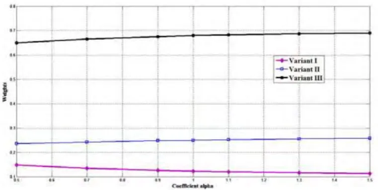
Figure 1.1 Graph result of the sensitivity analysis. 4
Figure 2. 1 Configuration of 5-axis machine tool. 8
Figure 2. 2 Type configuration of 5-axis machine tool. 8
Figure 2. 3 Multi-tasking machining systems. 10
Figure 2. 4 Type of coordinate system. 12
Figure 2. 5 A turn-mill part (a, b) outer step face turning features, (c) step milling feature, and (d) outer diameter turning feature. 12 Figure 2. 6 The model of multi-tasking machine: Mazak Integrex e410h (left) and
axes configuration (right). 12
Figure 2. 7 The machined mill-turn workpiece. 13
Figure 2. 8 Lead and tilt angles. 14
Figure 2. 9 The surfaces result. 14
Figure 2. 10 Comparison of resulting workpieces cross-section with uncompensated NC-program (left) and compensated tool path (right). 16 Figure 2. 11 Strategy of prismatic milling process and dialog panel for the settings of
machining simulation. 18
Figure 2. 12 The method of generating tool paths for the determination of external
and internal borders. 18
Figure 2. 13 Point milling 19
Figure 2. 14 Flank milling 20
Figure 2. 15 End milling, sweep milling and flank milling (from left to right). The red area is cutter contact locations with surface. 21
Figure 2. 16 Undercut and overcut 21
Figure 2. 17 Statistical method to analyse feed-rate, (f) and machining time, (t)
contribute to surface roughness. 24
Figure 2. 18 One of the graph result of carbon alloy steel (SAE8620). 25
Figure 3. 1 The top part of the car rim design. 36
ix
Figure 3. 3 Labeling the part for 5-axis. 38
Figure 3. 4 Labeling the part for turn-mill. 39
Figure 3. 5 The part operation setting in advance machining for 5-axis machine. 42 Figure 3. 6 The part operation setting in multi-slide lathe machining for turn-mill
machine. 53
Figure 3. 7 Important setting in machining parameter page. 60 Figure 3. 8 Result of bottom and inner wall from simulation (turn-mill). 62 Figure 3. 9 5-axis simulation result by using CATIA V5. 70 Figure 3. 10 The before and after compute tool path. 71
Figure 3. 11 The result of projection line. 71
Figure 3. 12 9-axis simulation result by using CATIA V5. 71 Figure 3. 13 Extra post processor in turn-mill program. 5XSIM is for milling
operation; BLIMIT & ANGTWO is to limit the B angle. 72 Figure 3. 14 Photograph show white color spray on the rim wheel. 73 Figure 3. 15 Photograph of the result obtain from the 3D scanner. 73
Figure 4. 1 Photograph show machining result by using HSC 70 linear (left) and
NTX 1000 (right). 74
Figure 4. 2 The shape analysis between 3D scan and CAD model. 76
Figure 4. 3 Mill-turn method in simulation. 80
Figure 4. 4 Turning method in simulation. 80
Figure 4. 5 Inspection from the surface. 81
x
LIST OF TABLES
Table 3.1 Machining process and tool used for the label part in fig 3.3. 38 Table 3.2 Machining process and tool used for the label part in fig 3.4. 39
Table 4.1 Comparison point. 77
xi
LIST OF ABBREVIATIONS, SYMBOLS AND
NOMENCLATURE
ANOVA - Analysis of variance BUE - Build-up-edge
CAD - Computer-aided design CAE - Computer-aided engineering CAM - Computer-aided manufacturing
CATIA - Computer Aided Three-dimensional Interactive Application CMM - coordinate measuring machines
CNC - Computer Numerical control CT - Computed tomography
D - diameter of tool(mm)
𝑓 𝑧– Feed per tooth
F – Feed rate (mm/rev)
HT-HR - Head Tilting and head rotating HT-TR - Head tilting and table rotating Mg- Magnesium
N – number of teeth/ flutes PSI - pounds per square inch S – spindle speed (RPM)
SEM - Scanning electron microscope TT-TR -Table tilting and table rotating
UTeM - University Teknikal Malaysia Melaka WPC- Basic Coordinates System Unit
xii
𝜋 - pi ∠ - Angle
1
CHAPTER 1
INTRODUCTION
1.1 Background
Accuracy is most important in all the fields. For manufacturer, production department produces the accuracy part products which fulfil customer requirement are most important than to hit the quantity part customers demand. Inspection department will reject all the parts with failed to maintain the accuracy which customer demand. The manufacturer will bear all the loss from the material cost, machining cost, and non-value added which is setting cost. To maintain dimension of accuracy is very challenging since there were many error will cause the error. The common error occur is human error. Nowadays, manual machine is replaced by Computer Numerical Control (CNC) machine to reduce the human error and improve the productivity of manufacturer due to CNC machine is more accurate and high efficiency. Computer Numerical control (CNC) is one in which the functions and motions of a machine tool are controlled by means of prepared program containing code alphanumeric data. CNC can control the motions of the workpieces or tool, the input parameters such as feed, depth of cut, speed, and the functions such as turning spindle on/off, turning coolant on/off. Computer numerical control (CNC) machine tools have been developed over the years, with the ability to machine high-precision products. CNC machine constitutes a major portion of machine tool manufactured today. The development of the machine from manual machine to CNC machine has significantly impacted engineering manufacture today. This is evidence from the replacement of conventional machines by CNC machines in many of the machine shops.
2 tools originally incorporated specific concepts of programmable logic. The first NC machines were built in 1940s. The metalworking industry began relying NC machine on paper punch-tape applications also can call G-Codes to program instructions used for manufacturing components. Nowadays, G-Codes is the generic name for a control language for CNC machines to tell the machine to move to various points at a desired speed, control the spindle speed, turn on and off various coolants, and all sorts of other things. G-codes also as communication tool to give programmer presented ideal of designer to machine. In the 1950s, slightly more advanced machines came along based on existing tools that were modified with motor designed to move the specific points that were fed into the system on punched tape. These early mechanisms were soon improved with both analog and digital computers. Then the introduction of computer technology into the concept of numerical control led to what we now know as computer numerical control, CNC. There was different type of CNC machines with various of configuration, but all the concept of CNC machine was same. The basic configuration of CNC machine is the axis which is X, Y and Z axis. So, the basic of CNC machine is 3-axis milling machine and 2-axis lathe machine. CNC machine with more than 3-axis is advance which consist rotate function for the three basics axis which A (rotate around x-axis), B (rotate around y-axis) and C (rotate around z-axis). Now, many configurations of CNC machines are produce due to can machining more complex parts as compared to 3-axis CNC machine.
3 capable in CAD, CAM, and CAE. With this advantage, I choose CATIA V5 as my tool to generate tool path and modify the part design of car rim wheel.
There are various technologies are used to manufacture original BMW light alloy wheels. Light alloy wheels can be manufactured from either cast or forge. Casting method is the process of the entire wheel including the styling area is cast in a liquid of metal. Forging method is processed wheel is forged from a solid piece of metal. Next process to reduce the weight of wheel by using flow-forming and undercut method which suitable for a cast and forge wheel. Flow-forming is a type of method to create a thinner rim base wall and undercut is used removed from the spokes through milling, non-strength related mass is reduced. Then surface finishing surface by powder coating which gives the wheel corrosion resistance to environmental factors such as corrosive road salt. The material used to manufacture wheel must be low density to reduce the weight, ability to withstand physical impact, corrosion resistance to the normal and saline atmosphere and fatigue resistance. Basically, hypo eutectic AL-Si primary alloys with 7 to 12 % silicon content, varying content of magnesium, low iron and minor impurity concentrations is used to manufacture wheel.
4 1.2 Problem statement
The problem of this project is without any research have been done before for comparison between 5-axis simultaneous and 9-axis turn-mill machine. The insufficient of the research caused lack of real data to compare of these two machines. Therefore, conduct this project all the expectation result is based on the configuration and superiority of machine.
[image:20.595.151.532.488.679.2]According Bologa et al. (2016) research about 5-axis simultaneous CNC machine (variant 3) on improving the setups time and machining accuracy of part as compared to 3-axis CNC machine-tool (variant 1), and 3+2 as well as 3+1 indexed CNC machine-tool (variant 2). Theoretically, 3-axis CNC machine-tools able machining many parts with the increased setup time and less complexity and accuracy. With indexed CNC machine-tools capable to improve the setup time, more geometrical complexity and accuracy of the parts as compared to 3-axis CNC machine-tools. Continuous 5 axes CNC machine-tools are more advantage on reduce the setup time, more geometrical complexity and high accuracy on machining the parts with compared to the others. They analysed the sensitivity of these three types of the CNC tools. 5-axis CNC tool consist high sensitivity than the other CNC machine-tools, the graph result as shown below.
Figure 1.1 Graph result of the sensitivity analysis.
5 Based on the above research,I can make one simplest hypothesis that is the 5-axis simultaneous CNC machine-tools is more accurate than 3-5-axis CNC milling machine-tools. Nevertheless, my aim of this project is regarding the comparison accuracy on 5-axis CNC milling machine and 9-axis turn-mill machine. Therefore, another assumption can be made is the 9-axis turn-mill can machine more accurate as compare to 5-axis simultaneous machines. Based on the configuration of turn-mill and 5-axis simultaneous CNC machine, I can surmise that the 9-axis turn-mill CNC machine consists low machining time than 5-axis simultaneous CNC machine. While NTX 100 can move simultaneously in 5 axes are C1, X1, Y, Z1, and B, which same with HSC 70 linear, the others 4 axes move in sequence with 2 spindle heads. Since 9-axis has this advantage, means that can reduce setups time and improve the machining time.
1.3 Objective
i. To compare surface accuracy and machining time between 5-axis simultaneous and 9-axis with same software and same parameters.
ii. To understand the configuration of HSC 70 linear (DMG MORI 5 axis milling machine) and NTX 1000 (9-axis turn mill machine)
6 1.4 Scope
7
CHAPTER 2
LITERATURE REVIEW
2.1 Five-axis simultaneous CNC machine
Every standard CNC machine must have linear motion along the X, Y, and Z axes. 5-axis machines have two additional axes of rotation. There are 3 type rotation axes are A, B, and C axes which rotates around X, Y, and Z axes respectively. What is the 5-axis machining? In 5-axis machining, the additional rotary axes will rotate about two of those three primary axes.
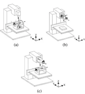
8 Figure 2. 1 Configuration of 5-axis machine tool
(Adapted from Hwang et al. (2015))
Figure 2. 2 Type configuration of 5-axis machine tool: a) table-rotating/tilting type; b) spindle-notating/tilting type; c) table/spindle-tilting type.
(Adapted from Jung et al. (2002))
[image:24.595.215.493.277.585.2]