Rochester Institute of Technology
RIT Scholar Works
Theses Thesis/Dissertation Collections
8-1-2011
Routing protocol evaluation and development of a
fully functional simulation environment for
vehicular ad hoc networks
Matthew Prokop
Follow this and additional works at:http://scholarworks.rit.edu/theses
This Thesis is brought to you for free and open access by the Thesis/Dissertation Collections at RIT Scholar Works. It has been accepted for inclusion in Theses by an authorized administrator of RIT Scholar Works. For more information, please [email protected].
Recommended Citation
Routing Protocol Evaluation and Development Of A Fully
Functional Simulation Environment For Vehicular Ad Hoc
Networks
by
Matthew J. Prokop
A Thesis Submitted in Partial Fulfillment of the Requirements for the Degree of Master of Science in Computer Engineering
Supervised by
Dr. Andres Kwasinski
Department of Computer Engineering Kate Gleason College of Engineering
Rochester Institute of Technology Rochester, New York
August 2011
Approved By:
Dr. Andres Kwasinski
Department of Computer Engineering, RIT Primary Adviser
Dr. Marcin Lukowiak
Department of Computer Engineering, RIT
Thesis Release Permission Form
Rochester Institute of Technology
Kate Gleason College of Engineering
Title: Routing Protocol Evaluation and Development Of A Fully
Func-tional Simulation Environment For Vehicular Ad Hoc Networks
I, Matthew J. Prokop, hereby grant permission to the Wallace Memorial Library to
repro-duce my thesis in whole or in part.
Matthew J. Prokop
Dedication
This thesis is dedicated to my wife, my parents, my family and friends. Without their help
and constant support it would not have been possible. It is also dedicated to my late
grandfather, who has always done so much for me and expected nothing in return. You
Acknowledgments
I am grateful for my thesis committee and the guidance they have provided throughout the
entire process. I am also grateful to Harshad Phule, David Layerle and Timo Bolse for
Abstract
A Vehicular Ad-hoc Networks (VANET) is an area of wireless technologies that are
attract-ing a great deal of interest. There are still several areas of VANETS, such as medium access
control, security and routing protocols, that lack large amounts of research. There is also a
lack of freely available simulators that can quickly and accurately simulate VANETs. One
of the two main goals of this thesis was to develop a freely available VANET simulator and
to evaluate popular mobile ad-hoc network routing protocols in several VANET scenarios.
The VANET simulator consisted of a network simulator, a traffic (mobility simulator) and
used a client-server application to keep the two simulators in sync. The VANET simulator
also models buildings in order to create a more realistic wireless network environment. The
second main goal of this thesis was to provide an evaluation of the routing protocols that
are commonly used in mobile ad-hoc networks, which will apply to VANETs. Ad-Hoc
Distance Vector routing (AODV), Dynamic Source Routing (DSR) and Dynamic MANET
On-demand (DYMO) were initially simulated in a city, country, and highway environment
Contents
Dedication. . . iii
Acknowledgments . . . iv
Abstract . . . v
1 Introduction. . . 1
1.1 Motivation . . . 1
1.2 Thesis Statement . . . 3
2 Related Work . . . 4
2.1 Architecture for Vehicle Safety Communications . . . 4
2.2 DYMO Protocol . . . 6
2.3 Evaluation Criteria . . . 6
2.4 Routing Protocols . . . 8
2.4.1 Ad-hoc On-Demand Distance Vector Routing . . . 8
2.4.2 Dynamic Source Routing . . . 10
2.4.3 Dynamic MANET On-Demand Routing (DYMO) . . . 13
3 Research Work . . . . . . . . . . . . . . . . . . . . . . . . . . . . . . . . . 15
3.1 VANET Simulations . . . 15
3.1.1 Currently Available VANET Simulators And Tools . . . 16
3.1.2 Wireless Network Simulators . . . 17
3.1.3 Traffic Simulation . . . 19
3.1.4 Simulator Coupling . . . 20
3.1.5 Simulation Setup . . . 21
4 Simulation Setup . . . . . . . . . . . . . . . . . . . . . . . . . . . . . . . . 24
4.1 The Simulator . . . 24
4.3 The Simulations . . . 27
4.4 Evaluations . . . 28
5 Results and Analysis . . . 30
5.1 Throughput Results . . . 31
5.2 Latency Results . . . 33
6 Conclusions . . . 42
7 Future Work . . . . . . . . . . . . . . . . . . . . . . . . . . . . . . . . . . 45
List of Figures
2.1 Dynamic Local Peer Group Examples [1] . . . 6
2.2 Two DYMO examples [2] . . . 7
2.3 Route Discovery for DSR Routing Algorithm [3] . . . 11
3.1 Example of a NED file . . . 19
3.2 TraCI Connection Example [4] . . . 22
4.1 VANET node model in Omnet++ . . . 25
4.2 TraCI Message Format [4] . . . 26
4.3 City Mobility Network . . . 28
4.4 Country Mobility Network . . . 29
4.5 Highway Mobility Network . . . 29
5.1 Throughput in bits/second for city environment . . . 36
5.2 Throughput in bits/second for highway environment . . . 37
5.3 Throughput in bits/second for country environment . . . 38
5.4 Latency in seconds for city environment . . . 39
5.5 Latency in seconds for highway environment . . . 40
List of Tables
1.1 Examples of VANET applications [4] . . . 2
Chapter 1
Introduction
Vehicles have been constantly evolving since their creation more than one hundred years
ago. Some of the latest advantages include research in the field of wireless sensor networks
which will allow a vehicle to communicate with other vehicles located within its
neigh-borhood. Vehicular Ad-Hoc Networks (VANET) are a dynamic ad-hoc network, in which
vehicles are continuously entering and leaving[5]. This type of network allows for
com-munication between vehicles and with any other roadside infrastructure. Within a VANET,
there are two types of networks to which nodes belong: vehicle and data. Vehicle networks
consist of physical cars and the paths they take. Data networks consist of the
communi-cation between the nodes on the traffic network. In VANETs, important information can
be gathered and relayed to other vehicles within the traffic network via the data network.
This information can then be used within applications implemented for VANET-capable
vehicles.
1.1
Motivation
VANETs are a type of mobile ad-hoc network (MANET) that allow vehicles to
communi-cate with other vehicles and roadside infrastructure [5, 4, 6, 7]. Projects, such as Fleetnet [8]
or Networks on Wheels [9], have already covered some of the aspects of vehicle to vehicle
communication, however, many aspects still remain uncovered. They include high
(MAC) schemes, efficient data dissemination protocols, security, and routing protocols, to
name some of the most critical ones [10]. The research that is proposed in this document is
focused on evaluating the routing protocols that can be used in an ad-hoc network in order
to provide lower latencies and more reliable communication.
Within a VANET, there can be several different types of scenarios in which vehicles
are located in (e.g. city, country, highway) which play a role in the routing algorithm that
should be used. With an evaluation of routing protocols, this will determine how well
each tested protocol will work in the different environments. As a results, this will open
doors to many applications in several domains including safety, route planning, and
emer-gency vehicle avoidance which can all be based on simple driving events called mobility
primitives[4]. Examples of VANET applications and their mobility primitives are shown
in 1.1. Each of the applications are sorted based on the type of information that would
be relayed to the driver, the Use Cases. The use cases are made up of different mobility
primitives that the VANET application in each vehicle monitors. In order to determine if
there is a traffic congestion or forward collision warning, for example, each vehicle needs
to monitor the primitives of its vehicle and the neighboring vehicles. The neighboring
ve-hicles need to send this information via the wireless ad-hoc network, therefore creating a
[image:12.612.128.491.486.665.2]need for efficient routing protocols to deliver the information in a quick and timely manner.
One of the possible applications of VANETs is trip routing that utilizes different
con-ditions on the roads to plan the best route. Drivers could choose to plan routes based on
fuel efficiency, distance, or even road conditions (i.e. congestion, slippery pavement, etc).
In order to determine the best path based on a road condition, the possible paths need to be
evaluated from the vehicle of interest by communicating with the vehicles on those paths.
This will allow the vehicle of interest to get a view of the roads and decide on a path.
This can be done, except when there are long distances or gaps between VANET-ready
vehicles which prevent successful vehicle path routing. The reason that the path routing is
obstructed is because the ready vehicles cannot communicate with other
VANET-ready vehicles which does not allow for the information to be communicated. In order
to make this process more successful, three chosen routing protocols are evaluated in this
work which helped determine which protocols work the best in the different topologies.
1.2
Thesis Statement
The goal of this thesis was to examine the effects of message routing in the data network
of a VANET when a vehicle is located in different traffic topologies. Along with the
pro-vided results, a complete analysis examined how the different traffic environments effect
the VANET’s throughput and latency. In order for a vehicle to successfully plan a route, it
needs to communicate with the vehicles on the roads ahead of it. Gaps between vehicles
cause VANET-ready vehicles to loose communication with each other, which causes the
applications to not work. This can be a concern, for example, when trying to plan a route
based on traffic congestion. Due to the lack of simulation tools for VANETs, this
Mas-ter’s thesis also provides an easy to use simulation environment with an in-depth study of
Chapter 2
Related Work
Some research has already been done in the areas of VANET applications and traffic safety.
The following sections will give a brief overview of some of this research, which will aid
in the research for this project.
2.1
Architecture for Vehicle Safety Communications
One of the issues associated with VANETs is the organization of neighboring vehicles/nodes.
Proposed in [1], Local Peer Groups (LPGs) can be used as a first step for providing almost
instantaneous communications for vehicle safety communications.
In order for Vehicle Safety Communications (VSC) to work properly, cars cannot
sim-ply be equipped with wireless communication hardware and deployed onto the vehicle
network. This will result in data network problems, especially data network interference
as neighboring vehicles try to send out warning messages with no transmission guidelines.
By grouping vehicles, message transmission and relaying can easily be coordinated along
with controlling the range and direction of messages.
LPGs provide tight coordination between vehicles in the same area and looser
coor-dination of vehicles in the neighborhood. Two basic LPGs have been proposed by [1]:
stationary LPG and dynamic LPGs. Stationary LPGs are location based and well defined,
however, they do require that nodes contain a GPS device to determine LPG membership.
LPGs consist of vehicles in the immediate vicinity to form an LPG based on radio coverage
in which nodes can leave or join at random. Two forms of a dynamic LPG can be used:
LPG with Relative Ordering and LPG with Linked Equivalent Cells. LPG with relative
ordering use a vector to define a vehicle’s location in the LPG, similar to an index for an
array. LPGs with linked equivalent cells (LECs) are used in high density areas in order to
cut down on overhead. The main purpose behind the LEC is to assign an LPG to vehicles
that are traveling together and have similar radio coverage.
LPGs use different types of control packets to collect and maintain group membership
information. Within an LPG there are three types of nodes: Group Head, Member, and
Border Node [11]. A group head (GH) is the LPG controller and can change at any time.
The GH sends out a heartbeat message in order to define the LPG membership. When a
member node receives the heartbeat, it will rebroadcast the message and reply to the GH
with a membership request message. In order to avoid creating too large of an LPG, the
heartbeat contains a hop limit which is the maximum number of times the message can be
re-broadcasted. The boundary nodes, which are member nodes as well, are chosen nodes
that can overhear control packets from a neighboring LPG.
There are two types of routing related to LPGs. Intra LPG routing takes place within
each individual LPG and is table driven[11]. As the GH sends out the heartbeat messages,
the member nodes that overhear the messages use the node information within the heartbeat
and member responses to build its routing table. The farther the messages are relayed, the
more detailed the routing tables get. Inter LPG routing uses on-demand routing principles
but does not flood the network with route requests [11]. The routes traveled within
inter-mediate LPGs is still handled by the intra LPG routing protocols. Travel between LPGs is
made possible by the boundary nodes. The boundary nodes overhear the neighboring
Figure 2.1: Dynamic Local Peer Group Examples [1]
2.2
DYMO Protocol
Proactive, reactive and hybrid protocols are the three different categories of routing
proto-cols for ad-hoc data networks, according to [2]. The first is a proactive routing protocol,
which relies on the periodic broadcast of data network topology. This type of protocol
en-sures that all nodes always have an updated knowledge of paths to other nodes. In order to
do this, a large amount of data network resources have to be use, which can severely limit
the amount of data that can be transferred. The second category, reactive routing
proto-cols, can be viewed as a solution to proactive routing protocols because they only search
for a route when one is needed. Some popular reactive protocols are DSR, AODV, and
DYMO. Lastly, hybrid routing protocols are a combination between proactive and reactive
protocols. The last protocol, hybrid protocols, exploit the fast delivery of packets from the
proactive protocols and the low overhead from the reactive protocols. A typical example is
the Zone Routing Protocol (ZRP)[2].
2.3
Evaluation Criteria
In [2], Christoph Sommer presents some necessary criteria that can be utilized in the
sim-ulations of ad-hoc routing protocols. One of these criteria is a proper simulation
Figure 2.2: Two DYMO examples [2]
simulate the ad-hoc wireless network along with the INET Framework. INET is a freely
available extension for Omnet++ which comes bundled with simulation modules. It
pro-vides modules to simulate the various layers of the Internet protocol suite (e.g. TCP, UDP,
IPv4, etc...). A mobility framework was later added to the INET framework to help aid in
modeling the spatial relations of nodes.
In order to properly evaluate the protocol, two models were made to use the routing
protocol in an Omnet simulation. The two implementations are shown below in Figure 2.2.
A full featured and minimal implementation are provided for the reasearch in [2]. For the
DYMO protocol, [2] uses the following issues as the different criteria for evaluation:
• Data Network topology and mobility issues
• Parameter settings and traffic patterns
• Performance metrics
• Validation
• Simulation control
2.4
Routing Protocols
Some work has already been done toward the development of VANET routing protocols.
Some of the protocols that can be associated with VANETs are Ad-hoc On-Demand
Dis-tance Vector (AODV), the Dynamic Source Routing (DSR), and the Dynamic MANET
On-demand routing protocols (DYMO).
2.4.1
Ad-hoc On-Demand Distance Vector Routing
AODV is a routing protocol that was designed to be used with mobile ad-hoc networks,
which is the main reason for it being used[12]. The following merits of the AODV routing
protocol are also the reasons for its use in this work.
One of the key features of AODV and all other reactive routing protocols is that they
are not table driven. This means that routes are only created and maintained when there is
a need for that route (i.e. a source Node S, needs to send a message to a destination Node
D). Proactive routing protocols use a table to maintain routes over the network and require
a lot of overhead to keep this up to date. The table contains a partial copy of the network
topology as well as the cost between nodes. For the AODV protocol each node maintains a
table that contains the following information [13]:
• Destination
• Next hop
• Number of hops
• Destination sequence number
• Active neighbors for the route
The expiration time is a key feature of AODV because it helps to keep routes up to date.
After the expiration time, or lifetime, is exceeded the node will delete this route from its
table. If a route is frequently used then it will be updated each time a message is sent using
that specific route. The update will simply take the current time and add a paramter, called
the active route timeout, to it [12]. This will prolong the amount of time the route stays
active.
If a route is not contained in the node’s routing table then a proces called Route Request
(RREQ) begins. The RREQ process floods the network with RREQ messages until the
destiation node or hop limit is reached. The RREQ messages that the nodes send out
contain the following [14]:
• Source Address
• Request ID
• Source Sequence Number
• Destination Address
• Destiantion Sequence Number
• Hop count
When a node wishes to initiate a RREQ, it will broadcast a RREQ message to all of its
neighbors. When receiving a RREQ message, each node will check the source address and
request ID so it does not process the same RREQ more than once. If the message has not
been processed yet the node will check its routing table and perform one of two options. If
a route already exists in the table with a sequence number greater than the one in the RREQ
or the current node is the destination, it will generate a route reply (RREP) message to be
sent back to the source. Otherwise, the node will rebroadcast the RREQ with an update hop
count. A RREP message is used to reply to a RREQ because a valid path has been found.
• Source address
• Destination address
• Destination sequence number
• Hop count
• Lifetime
In the event that a node goes missing from a path (it no longer exists) a route error
(RERR) will be sent out. When a node receives a RERR message, it will update its routing
table by removing the node that is causing the RERR and any related routes. The purpose
of this is to eliminate the use of the bad route in the future.
The most important feature of AODV routing is the use of sequence numbers [12]. The
sequence number helps to keep routes in the routing tables fresh. When a nodes receives
a message with a route and a sequence number it will compare what is in its own routing
table. If the sequence number in the message is greater than what is in the nodes table,
the route will be replaced because the new route is newer. Sequence numbers also help to
eliminate nodes from creating the infinite loop problem [15].
Another feature of AODV is the use of HELLO messages[12, 16]. These messages are
broadcasted to all nodes within a source node’s transmission zone and can be used to learn
of new neighbors and other changes in topology such as link breaks. HELLO messages
are only sent out periodically and when a node fails to receive messages from a known
neighbor then the path is marked as broken.
2.4.2
Dynamic Source Routing
Dynamic Source Routing (DSR) is another routing protocol that was specifically designed
for use in multi-hop mobile ad-hoc networks[3]. Like AODV, DSR is a completely self
organizing algorithm that can configure itself without the use of any central infrastructure.
Figure 2.3: Route Discovery for DSR Routing Algorithm [3]
• Route Discovery: the process of discovering a route from a source to a destination.
• Route Maintenance: allows for the topology of the network to change and a nodes
routing table to remain fresh.
Route discovery and maintenance do not run on a periodic schedule, rather they run
only on demand. AODV uses periodic messages (HELLO message) to learn of the wireless
network’s topology, however, DSR does not use any type of periodic packets or messages
at any level. The purely on demand behavior of the DSR routing algorithm allows it to
cut down network overhead compared to algorithms that do use it[3]. DSR allows for the
nodes to learn of changed topology quickly because a node has the ability to cache routing
information overheard on the network. This becomes quite useful because multiple routes
that lead to the same destination can be stored in a node’s routing table. In the even that a
transmission fails, a node can try another stored route rather than initiating another route
discovery.
Route discovery is the process that the DSR algorithm uses to find a route to send a
packet from source to destination. Normally when a node wishes to send a packet to some
other node the sequence of hops that need to be taken are put into the message. When no
route is present the source node transmits a route request (RREQ), similar to AODV. Each
node broadcasts the message until it reaches the destination. Once at the destination node,
that node will send back a route reply (RREP) to the source.
As shown in the Figure 2.3 node A wishes to send a packet to node E. Node A initiates
a route discovery with an RREQ that contains node A as the initiator, an empty route record
the route is built because each node appends itself to the route record in the RREQ. A node
will drop the route request if it has seen another route request from the same initiator with
the same request ID or the node’s address is already present in the route record.
Once the route request reaches the intended destination, the destination node will send
a route reply back to the initiator. In the Figure 2.3 node E initiates the route reply by
examining its own route cache for a route back to node A. If a route exists it will use that
route, however, if no route exists a new route discovery must be initiated. To avoid the
possibility of infinite route discoveries, node E will piggyback the route reply on the new
route request [3]. For protocols that support bidirectional links, such as IEEE 802.11, the
destination node will use the reverse route that is located in the route request. This prevents
flooding the wireless network with route requests, however, it does not allow for nodes to
learn of new and more efficient paths [3].
In the event that a node cannot successfully transmit a packet to the next hop, it needs
to perform route maintenance. When forwarding packets along a source route, each node
on the route is responsible for the successful transmission of the packet to the next hop.
This reply can either be done by using an existing part of the MAC protocol in use or done
passively [17]. In the Figure 2.3, node B can confirm the receipt of the packet to node C by
listening to see if node C tries to forward the packet again. A route error message is sent out
in the event that a node does not receive a successful transmission. The route error message
is sent back to the original sender with the location of the broken link so the appropriate
change in the table can be made.
One feature of the DSR routing algorithm is that is allows for nodes to cache route
information that is passed along in route requests or route replies. Nodes can gather this
information by messages addressed to that node, messages that were broadcasted, or
mes-sages obtained while a node’s network interface is in promiscuous mode. This allows nodes
to learn of the changing network topology, however, it can cause an issues if routes are
as-sumed bi-directional when they are uni-directional [3]. Another feature of DSR includes
route error message to the original sender but it may not discard the packet. Instead, the
node will look for a route in its own route cache and try to send the message to the original
destination.
2.4.3
Dynamic MANET On-Demand Routing (DYMO)
The final routing protocol that was used for evaluation is the Dynamic MANET On-Demand
(DYMO) routing protocol [18]. The DYMO routing protocol is another protocol that is
designed for use in mobile wireless ad-hoc networks. Unlike the work in [19], this
imple-mentation will be integrated right into the network layer and not as part of the application
layer. Just like DSR and AODV, DYMO consists of two main operations: Route Discovery
and Route Maintenance.
DYMO route discovery is performed similar to the AODV and DSR routing algorithms.
When a node needs to send out a packet to another node it will first search its route cache
or routing table to see if an up to date route exists. If one does, the source node uses that
route to send the packet to its destination. However, if a route does not exist the node must
go through a process to find a path to the destination, called route discovery. The source
node creates a route request (RREQ) message to send out to all neighboring nodes. The
RREQ contains the following information [20]:
• Destination Address
• Sequence Number
• Hope Count
• Next Hop
• Next Hop Interface
• Is Gateway
• Valid Timeout
• Delete Timeout
The source node will then send out the RREQ via broadcast to all of the surrounding
nodes. The receiving node will look at the packet to make sure that it has not seen it before
and if it has the packet will be discarded. If it has not been seen before, the node will then
start to look at the information contained inside of the RREQ. If the routing table does not
contain any information for the originator, the node will create a spot for it and update the
the data in the RREQ. If an entry already exists but the sequence number indicates there is
out of date information then the RREQ is dropped. Lastly, if the sequence number indicates
there is new information in the RREQ then the data in the routing table is updated and the
RREQ is passed on. Once the RREQ reaches the destination node, that node will then form
a route reply (RREP) that contains the new route and is sent back along the reverse path.
Route maintenance is the other operation that the DYMO protocol does. The only time
that route maintenance is done is when a node receives a message that it does not have a
route for. In other words, the ’next hop’ node could have moved out of range or its network
interface could be down which would prevent that node from receiving messages. Route
maintenance is invoked when a data packet cannot be delivered to the next hop because no
path is available. The node that must perform route maintenance will create a route error
message (RERR), it will look at the node that is causing the issue and create a list of all
entries in the routing table that depend on that node as the next hop. The RERR is then sent
back to all nodes that are affected by this network issue.
One feature to note about DYMO is that it does not support uni-directional paths [18].
This is usefule when caching routes overheard in the network because it can use those routes
to forward packets, providing they are valid at the time of need, without the use of route
discovery. Another feature of DYMO is that its nodes will cache routes similar to the way
nodes in DSR do. As RREQs and RREPs are overheard, the nodes that are eavesdropping
Chapter 3
Research Work
Vehicular ad-hoc networks are becoming a useful tool for safe and comfortable driving,
however, many challenges are still encountered when trying to implement tools for VANETs.
Data transfer and applicable routing protocols are the main topics that are covered in this
research.
3.1
VANET Simulations
One of the primary goals was to develop a simulation tool that will allow for accurate
simulation of VANETs as is needed by this research and future endeavors. Current VANET
simulation tools are either not publicly available or not efficient for examining VANETs
with many changing variables [21]. The tools that are not publicly available were developed
by companies to accommodate for their needs with VANET simulations. Tools that are
publicly available are not suitable for the more complex VANET simulations because they
are based on mobility trace files. This can be an advantage if the simulation environment
never changes, however, when the need arises to modify environment variables that cause
a change in node mobility paths, the trace files need to be regenerated in order to work with
3.1.1
Currently Available VANET Simulators And Tools
CanuMobiSim Communication in Ad Hoc Networks for Ubiquitous Computing
(Canu-MobiSim) is a java based mobility simulator that can be used towards simulation of VANETs.
CanuMobiSim is not a data network simulator, rather it provides the traces that can be used
to map mobility of vehicular nodes. CanuMobiSim can generate traces for the smooth
mo-bility model, pedestrian, graph walk and several others [22]. One of the drawbacks of this
tool is that it lacks the ability to create random mobility traces. This tool works by taking
data from Geographical Data Files or user defined maps and extracts the node mobility to
create the trace files that can be used with NS-2.
NS-2 and NS-3 NS-2 is a network simulator that has been around since the late
1980s[23]. This simulator works by executing code written in C++ and OTCL. Based
on the execution of the code it will generate a file that is used by the Network Animator
(NAM) to put the nodes in their proper places and accurately simulate the network. NS-2
includes many libraries to simulate many wireless networks, however, it initially lacked
the capability to simulate multiple radio interface[23]. With technology changing, a later
release offered support for this important aspect.
A newer version of NS-2, written in purely C++ has been released in 2008 called NS-3.
NS-3’s initial release was closely followed by nine other releases that added more
function-ality onto the base program. Its main goal was to develop an open simulator that could be
used for modern networking needs. NS-3 contains support for multiple models, including
WiFi, WiMAX, and static or dynamic routing protocols. NS-3 releases a new stable version
of their software every three months with newly developed and validated tools [24].
GlomoSim and Qualnet Glomosim is another very popular network simulator but
not quite as popular as the previously discussed NS-2. Glomosim’s main focus for network
simulations is on wireless networks [22]. Coded completely in Parsec, Glomosim’s
with it. One of the positives of Glomosim is that it is able to simulate large networks due
to its ability to split work between CPUs. All the work needed for a simulations will be
divided up into separate processes which will also create less work and quicker
simula-tions. For most simulations in Glomosim the Random Waypoint Mobility model is used,
however, there have been other projects that allow Glomosim to use other models as well.
The GEM project is a major project that helps Glomosim have more realistic simulations
[25]. Glomosim was later re-released as a commercial version called Qualnet.
QualNet is written entirely in C++ and is modelled as a state machine, as most other
simulators. It has the ability to run on various platforms, including Mac and Windows.
Along with the many libraries that Qualnet is equipped with, it also supports the ability to
create 3D visualizations that can support up to 20k nodes [22].
3.1.2
Wireless Network Simulators
Omnet++ is a C++ program written to simulate communication networks, multiprocessors
and other distributed or parallel systems[26]. This simulator is open sourced and is free for
non-profit use. Omnet++ was designed to do the following [26]:
• Enable large scale simulations with reusable models.
• Provide easy tracability and debugging.
• Simulations software should be modular.
• Analyze input and output files with common software.
In order to provide a large scale simulations with reusable models, Omnet++ uses
mod-ules to develop the different components of the simulation. Simple modmod-ules are the most
basic modules as they provide extremely basic functionality. Compound modules are
cre-ated by grouping simple modules together to create an object with a complex functionality,
such as a vehicle equipped with a IEEE802.11b radio. Modules contain different
can be represented as strings, numbers or pointers. In order for the modules to
communi-cate with each other they exchange messages. Each message contains a time stamp and any
data relative to the communication between two modules. Modules are connected to each
other with a ’connection’ module to the appropriate gates.
Omnet++ monitors the communication patterns of the VANET nodes along with the
use of the INET Framework. A framework is a plug in for Omnet++ that contains many
modules (network interfaces, different layers, applications, example nodes, etc) for use in
simulations. This INET framework provides the necessary modules to simulate different
types of networks and network layers[27], including the IEEE802.11b wireless ad-hoc
net-work used in this net-work. The Obstacles project, combined with the INET framenet-work, gave
Omnet++ the ability to model buildings, which allowed for a more realistic simulation of
a VANET. This will not be as important in a rural setting, however, in a city environment
there are many buildings that will play into how the wireless signals are transmitted.
Modules in Omnet++ are connected to each other’s input and output gates with the use
of simple ’connection’ modules. These connections are all defined in a file that uses the
NED language, as shown in 3.1. Omnet’s own topology description language is what the
user uses to define how their models will be set up [26]. Similar to how modules were
designed to be reusable, NED models are also reusable and designed to work with other
NED files to create much larger models. A nice feature of Omnet++ is that it uses a two
way editor to create and modify the NED files that make up the environment. One option
for NET editing is through a generic text editor, which Omnet++ provides or the use of
a third party editor. The second option for editing is through Omnet++ GUI that allows
for dragging and dropping of pre-defined and user-defined NED files and connections. In
figure 3.1, the uppper portion of the image shows the graphical editor while the lower
Figure 3.1: Example of a NED file
3.1.3
Traffic Simulation
Simulation of Urban Mobility(SUMO) is a C++ application developed to simulate the
movement of objects along a road network. It is a free and open sourced simulator that
was originally developed for use of the employees of the Institute of Transportation at the
German Aerospace Center. Along with being able to model small areas, SUMO is also
capable of modelling traffic in large networks, such as cities or highway networks, without
any changes.
SUMO simulations are considered to be multimodal, meaning that every object in the
simulation is simulated [28]. Not only are cars simulated, SUMO also takes into account
any public transportation system, train networks, and even traffic lights if desired. Each
object in the simulation is modeled individually, so no two vehicles are the same.
Dur-ing each simulation step the values for every node are updated. One of the drawbacks of
SUMO is that the user is limited to a one second simulation step. During simulation, the
the maximum speed for a road, right of way to other vehicles, and even how fast or slow a
vehicle can speed up.
The latest version of SUMO offers the following features [28]:
• Collision free vehicle movement
• Different vehicle types
• Multi-lane streets with the ability to change lanes
• Right of way at intersections
• Raw output for each simulation
• Input from XML files
SUMO comes with quite a few tools that can help create any type of simulation. Some
of the most useful tools are the network generator and the route generator [?]. SUMO
al-lows for the import of freely available maps from sources such as Open Street Maps [29],
however SUMO also comes with its own network generator. Netgen[30], the tool to create
maps, and Netconvert[30], a tool to import maps, do not include route files in their output.
Route files instruct a vehicle where to go next and need to be generated with Duarouter,
SUMO’s route generation tool [30]. SUMO can also incorporate buildings, parking lots,
and other land marks with the use of Polyconvert. This tool can extract the needed
infor-mation from the imported map and will place it in an XML file, buildings.poly.xml, similar
to the way the other tools do, which will be used during simulation.
3.1.4
Simulator Coupling
To accurately model a VANET, Omnet++ and SUMO are connected with a technique to
synchronize node movement between two simulators. The Traffic Control Interface (TraCI)
is used to couple the simulators. Previous VANET simulation approaches used mobility
has the network and traffic simulators built in together, such as Groovesim [32]. The third
approach uses techniques similar to TraCI that couple the two simulators together. This
approach was chosen for this work because all software used in free and open source. The
separation of the simulators also allows for changes in the overall simulation environment
ot be made without having to regenerate trace files.
TraCI works in a client-server manner [4]. The TraCI server runs on the client PC as
a third application; it waits for TraCI clients to establish a connection. The TraCI client is
built into the network simulation, and in Omnet++ is part of the network node that is being
simulated. When the network simulation is started, the nodes will connect to the server
and wait for commands to be sent. Omnet++ will send a synchronization message to the
server to tell the traffic simulator, SUMO, to advance one step. SUMO will then send the
simulation results (vehicle coordinates) back to the network simulator.
Based on the work of [21], the network simulator was coupled with the traffic/mobility
simulator through a TCP connection. This allowed for each simulator to work
indepen-dently while maintaining a connection with the other simulator for accurate results. The
basic setup of this simulator remains relatively simple. The network simulator (Omnet++),
which was the master simulator, performed two essential tasks. The first is to maintain
the connections between the nodes in the wireless ad-hoc network. The network
simula-tor also controls the timesteps between the two simulasimula-tors which ensures that neither get
out of sync. Its task is to instruct SUMO when to advance to the next step. Once SUMO
completes its next simulation step, it sends back the updated location of all the nodes in
the traffic network. Omnet++ will then update the locations of the nodes in the network
and perform the necessary communication steps. Figure 3.2 shows an example of how the
client and server interact.
3.1.5
Simulation Setup
With the two simulators successfully coupled, there was still more to be done. A wireless
Figure 3.2: TraCI Connection Example [4]
fully simulate a VANET. The wireless network was setup to be based on the IEEE802.11b
standard, which is commonly used in VANET simulations [27]. The maps for the traffic
simulation consisted of three different environments. The purpose of using multiple traffic
environments was to expose the routing protocols to a variety of topologies rather than just
one. The first environment is a small area of a city that consists of blocks that are 100m
by 100m and contain buildings in each block. The second scenario that will be used is a
country environment. This environment has streets that go off in random directions and
have open spaces between them. They are not placed as close as the city environment
since country roads are much farther apart. The final traffic environment is a highway
environment, which consists of two two-lane roads that run parallel. Each road will act as
the highway lanes and consist of vehicles moving at a fast pace in opposite directions.
In order to accurately simulate the city environment, buildings needed to be added to
each city block. A separate work from [19] and work from Harshad Phule [33] model
buildings in a wireless network. In [19], buildings are integrated into the map for a
wire-less network with two moving nodes. Phule takes the work from [19] and expands it by
implementing the use of building as obstacles in this work’s developed VANET simulator.
The buildings that were placed in each city block act as obstacles by reducing the range
Chapter 4
Simulation Setup
The setup of the simulations is key to reproducing the results gathered in this work. The
following sections will outline the setup of the simulator and the simulations.
4.1
The Simulator
The simulator consists of several parts: the network simulator, the mobility simulator,
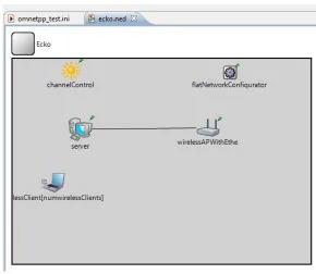
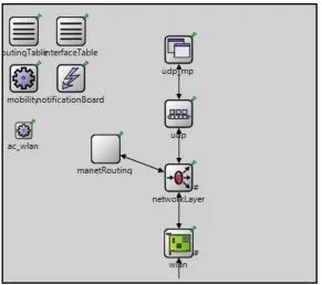
TraCI, the obstacle simulator, and the routing protocol interface. In figure 4.1, the
ba-sic layout of each VANET node is shown. It consists of a network interface card, network
layer, transport layer, application, and the routing protocol interface.
Each node in the simulation contains several major parts, the first part is the
wire-less network interface. Each network interface card supports IEEE 802.11b at a bitrate of
11Mbps. Each transport layer supports UDP only and is connected to a simple UDP
ap-plication that simply sends a message of 256 bytes to a specified node every quarter of a
second. The mobility module that is located in each node is what will interface Omnet++ to
the TraCI server in order to provide synchronization to the mobility simulator. Lastly, the
manetRouting module is the interface for the routing protocols. The manetRouting module
allows the user to quickly change between routing protocols by changing a parameter in
the Omnet++ simulation configuration file (omnet.ini) prior to starting the simulation.
Figure 4.1: VANET node model in Omnet++
such as the channelControl and the FlatNetworkConfigurator, as well as the
Annotations-Manager and the ObstacleControl module. These two modules must be enabled in the
Omnet simulation configuration file and will work together to draw the buildings in the
map. The obstacles simulator examines the wireless transmission present in the simulation
and recalculate the strength of the signal based on what obstacles are in the path.
4.2
Simulator Communication
To communicate back and forth, TraCI clients and server use a set of messages. In figure
4.2 the standard message format is pictured. For the TraCI commands there are three basic
groups [4].
The first group is used to control the simulation with the following commands:
• Simulation Step: signals the traffic simulator to perform the next step
Figure 4.2: TraCI Message Format [4]
• Move Node: Contains new coordinates for a vehicle/node.
The second set of commands are used to control the mobility primitives of each vehicle.
These commands effect a single vehicle and are :
• Set Max Speed
• Stop Node
• Change Lane
• Change Route
• Change Target (destination)
The third set of commands is used only for control of the simulation environment and
gather information. These commands include:
• Scenario: Get the dimensions of the scenario
• Position Conversion: converts between Cartesisan coordinates and the appropriate
• Driving Distance: Finds the distance on a path and the estimated time to get from
one to another.
4.3
The Simulations
Once the setup of the simulator and the node is complete, the final step in the setup
per-tains to how the simulations will run. Three files are necessary to define the movement of
the nodes in the mobility simulator, however, they will be loaded through Omnet++. The
first file is the net file, ’simulation.net.xml’, which defines the locations of the nodes in a
traffic network. The route file, ’simulation.rou.xml’, file defines the sequence of lanes that
each node will follow for its entire path. Lastly is the SUMO configuration file
(simula-tion.sumo.cfg) that defines how the simulation within SUMO is setup. For more
informa-tion see [30] for how these files are setup. There are several tutorials that provide
instruc-tions on how to create a basic SUMO simulainstruc-tions as well as a very detailed user manual in
the documents section. For the obstacles portion of the simulation, an ’obstacles.xml’ file
is used to define the locations of the buildings in the Omnet++ simulation.
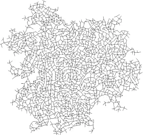
Each traffic environment consists of a pair of traffic topology (called a net) and route
files, the example traffic topologies can be seen in figures 4.3, 4.4, and 4.5. The city
envi-ronment is nine blocks wide and nine blocks high with each block being 100m by 100m.
The country environment is 10km wide with streets running in multiple directions. Lastly,
the highway environment is 4km wide with the upper two lanes moving traffic in the left
direction and the lower two lanes moving traffic in the right direction. Each traffic
environ-ment was simulated multiple times with two factors that changes: number of TxRx pairs
and traffic density. A TxRx pair is a pair of nodes that communicate with each other. One of
the two nodes is the sender and the other node is the receiver and all surrounding nodes are
only used to forward packets from source to destination. For each set of simulation runs
there was up to 10 TxRx pairs. The number of TxRx pairs was varied between one and
Figure 4.3: City Mobility Network
Simulations would start out with low density of 163 nodes, change to 247 nodes, and then
470 nodes. It was necessary to vary the traffic density in order to model how populated the
streets would be during different times of the day. This allowed to show the differences in
network performance while vehicle density was at different levels.
4.4
Evaluations
The simulations were run in five different sets. The only difference between each set was
the number of transmit and receive (TxRx) pairs that existed in the network. The goal
of varying the number of TxRx pairs was to create more data network traffic that would
have in impact on how quickly a message could get delivered between TxRx pairs. Within
each set of simulations there were 27 individual simulations that varied the scenario and
routing protocol used. Nodes were simulated in the three previously mentioned scenarios
and for each scenario all three routing protocols were simulated. The final parameter that
changes in the simulations was the density of the traffic, which varied from high density
Figure 4.4: Country Mobility Network
Figure 4.5: Highway Mobility Network
From each simulation, the average throughput and latency were recorded for
compar-ison of the protocols. This will allow for an in-depth analysis of the strengths and
Chapter 5
Results and Analysis
The routing protocols used for evaluation in this thesis are AODV, DSR, and the DYMO
protocols. Each protocol has had its own prior research, however, the three protocols were
used for data network analysis in different traffic environments. This showed the strengths
and weaknesses of each protocol when they were simulated in each of the different
vehi-clular traffic scenarios.
The routing protocols used in this work for evaluation are AODV and DSR. Research
for DYMO has already been done, however, DYMO was evaluated and used as a control.
Each of these protocols are designed differently, however, they are all designed for mobile
ad-hoc networks which make them play an important role within a VANET. To evaluate
each protocol in this work, they were implemented in nodes that represent individual
ve-hicles on a road network. The veve-hicles were equipped with the ability to communicate
with an IEEE802.11b wireless network with no central infrastructure for communications
(i.e. ad-hoc). Since there are different types of road environments, nodes were simulated
in a country, highway, and city environment. In the evaluation of each protocol, the use
of three different road environments showed which protocol works best for fast changing
environments and which protocols work bests for each specific environment.
Tables 5.1 and 5.2 were included to help aid in the analysis of the results. The charts
presented in the following results section provide an easier way to compare the simulations,
5.1
Throughput Results
The following section contains the throughput results from each of the simulations. All data
is provided in tables at the end of this section. The throughput was calculated by monitoring
the channel that the application transmits packets on and determining the speed at which the
packets are successfully transmitted. The results for each simulation scenario are shown
in figures 5.1, 5.2, and 5.3. The most noticeable result with these plots is that medium
and low traffic density during simulation in country environment is missing. Due to the
characteristics of a country environment, the nodes present in those two sets of simulations
were unable to find a complete path to transmit the packets. Within the country environment
the streets are a considerable distance away from each other, typically out of transmission
range of other nodes. Also, the streets in the country environment are not parallel like in the
city and highway environment. This causes the nodes to move in many directions compared
to the parallel and perpendicular directions of the city and highway environment, giving the
nodes an extremely limited time to communicate with each other. The high density traffic
simulations for the country environment were the only country simulations that results in
successful communication between the TxRx pairs.
The DSR routing algorithm proved to be the higher throughput transmitting algorithm
in the high traffic density city simulations. The high density traffic simulations in the
coun-try environment did result in some communication between the nodes. The DSR routing
protocol had the highest throughput with 5 TxRx pairs present on the map, the DYMO
protocol remained the most stable throughout all 10 simulations. DYMO had one outlier
with 4 TxRx pairs, however it increase as the more TxRx pairs were added. AODV did not
remain as stable as DYMO in that it was oscillating from high to low throughput over the
10 simulations. AODV is the only routing protocol used in the simulations that does not
cache route information in overheard transmissions.
The city environment simulations showed different results for the different traffic
sim-ulations. In the high density city simulations, the three routing protocols all started with a
protocol had the most drastic change, about 100bits/s, as the number of TxRx pairs were
increased. The DSR routing algorithm remained stable with throughput between 2200 and
1750 bits/s. The addition of extra network traffic did not have as big of an effect on the
overall throughput as it did with AODV. The DYMO protocol showed a similar dip in
throughput as the AODV protocol in that there was almost a 1000bit/s drop. Even though
the vehicles are slow moving, the changing city with the presences of buildings on either
side of the street did have an effect on each of the protocols. The medium density traffic
environment showed similar effects for each of the routing protocols. Looking at plot B in
figure 5.1, each of the routing protocols started at a high throughput with 1 TxRx pair and
finished at a level that was between 500 and 1500 bit/s lower with 10 TxRx pairs. DSR
showed the lower loss in throughput for the 10 simulations. The change to a low
traf-fic density environment caused the routing protocols to act differently. With few vehicles
present in the traffic environment, it creates fewer hop paths from source to destination.
The DYMO protocol had an increase in throughput from four to seven TxRx pairs because
of this, however, as the number of TxRx pairs increased the throughput dropped to a level
similar to where it started with a single TxRx pair.
The plots in figure 5.2 show the results obtained from the high, medium, and low density
highway simulations. The DYMO protocol showed an increase in throughput as the number
of TxRx pairs increased. The increase in the TxRx pairs causes an increase in the number of
nodes trying to communicate with each other, which causes the number of route discoveries
to be increased. This increase helps DYMO learn of more routes which allows the nodes to
send out their packets with an increased probability that a route already exists. The AODV
and DSR protocols do not experience this in the high and medium traffic density scenarios.
The low traffic density network has a different effect on the nodes because vehicles are
spaced farther apart. The DYMO protocol no longer has the positive slope it did with the
prior simulation and AODV actually gains throughput as the number of TxRx pairs increase
5.2
Latency Results
The latency results are important for applications that are time sensitive, such as collision
avoidance or emergency vehicle warning. These latency measurements were calculated by
determining the time between when the message left the sender and was received at the
destination.
In figures 5.4, 5.5, and 5.6located at the end of this section the latency results are shown
for simulations with multiple TxRx pairs in different low, medium, and high denesity traffic
environments. These are the same environments used in the throughput simulations. Recall
from the throughput simulations that the nodes in a country environment during medium
and low traffic density were not able to achieve an end to end route so the latencies were
not shown on plots figures because they are infinite. The nodes do have communication
among themselves, however, the source and destination nodes are not able to communicate
with each other so this is why the latency would be considered infinite.
In all seven plots, the most noticeable result is that the DSR routing protocol has the
highest average latency in all of the simulations and DYMO having the lowest latency. The
city environment resulted in some of the lowest latencies for DSR that ranged between
1.5 seconds and 6 seconds. The highway and country scenarios are the environments that
resulted in much higher latencies. For each of the highway environments, the DSR routing
protocol had the highest latency when the TxRx pairs remained low. As the pairs increased,
the latencies tended to decrease which is due to the amount of network traffic generated
from the increasing number of pairs and the ability to cache routes.
The second lowest latency routing protocol is the AODV protocol. This protocol
typi-cally had latencies that were under three seconds, which is a big difference in comparison to
DSR. The DYMO routing protocol also had very low latencies, typically less than one
sec-ond in all scenarios. When both of these protocols are compared back to the DSR protocol,
Chapter 6
Conclusions
In conclusion, the VANET simulator that was developed in this work proved to provide
quick simulations. By using TraCI to manage the separate simulators, the traffic and
net-work simulators were allowed to net-work separately while remaining completely in sync. The
use of obstacles in the network simulations provided for accurate simulations because it
limited the range a node could transmit packets. This was particularly useful in the city
simulations because of the presence of buildings on each block.
The results from the simulations showed some interesting results that help determine
how the routing protocols should be used. The DYMO routing protocol is best used in
ap-plication where latency (time to find a route and deliver the message) needs to be extremely
low. With DYMOs ability to cache routes and assume bidirectional paths, this routing
pro-tocol is ideal for low latency situations. AODV is another routing propro-tocol that could be
used in VANET applications because it also maintains a relatively low latency, even though
not as low as DYMO, that would allow it to be applicable for VANET applications. The
DSR routing algorithm proved to be a poor choice for a routing protocol in VANET
ap-plications because of the high latencies that are associated with it. Latencies as high as
twenty three seconds in a highway situation are not even close to a tolerable latency for
applications in such a high speed environment. Twenty three seconds, or even ten seconds,
is too long of a time for a message to be delivered in a VANET application and could result
in important safety information arriving to the vehicle too late. For VANET applications,
as possible in order to provide enough time for the driver to react. Take, for example, an
in-tersection collision avoidance application. As a vehicle approaches an inin-tersection it needs
to gather information about other vehicles, their location, and their velocity in order to
de-termine if any of the vehicles will cross the source vehicles path. If so, the driver needs to
be warned in order to take preventative action. If information is delayed, it could result in
an accident.
After analysis of the throughput results, its clear that each routing protocol performs
differently in each type of traffic environment. It is also clear that there are certain
traf-fic environments that are not suited for VANET applications. A city environment is one
traffic topology that is well suited for each of these routing protocols. Throughputs ranged
from about 500 bits per second to over 3000 bits per second in the city environments.
This is good for applications that need to transfer large amounts of data and even better
for applications that need to transfer smaller amounts of data. Highway environments had
throughputs from each of the routing protocols that were lower than those in the city
envi-ronments, however, they were still about 300 to 1700 bits per second which would allow
for applications to transfer messages between nodes. The country environment is clearly
not meant for VANET applications because it was only able to have nodes communicate
when the traffic density was high. As the density thinned out in the medium and low
simu-lations, nodes were not able to establish a path between source and destination to transmit
messages. With a country environments characteristics of streets placed far apart and faster
moving vehicles, it will be hard for end to end communication to occur, therefore, not being
suitable for applications that need reliable connections. In order to allow VANET
appli-cations to work in this environment another type of wireless network must be used that
allows for longer transmission ranges or use a modified IEEE802.11 radio with increased
transmission power.
Overall, the DYMO routing protocol seems to be the best choice for a routing
AODV routing protocol is a good second choice for a routing protocol, however, its
la-tencies averaged higher than DYMO but are still within a reasonable range. It would be
suggested to use this protocol in situation where network latencies may not be as
impor-tant. The DSR protocol is not recommended for VANET application use because of its very
high latencies. Also, as previously stated, the best environment for VANET applications is
the city network because of its high throughput and slow changing topology. A highway
environment is also acceptable for VANET application but larger amounts of data will be
Chapter 7
Future Work
This work provided a robust simulator for VANET applications and a comprehensive
anal-ysis of some of the available routing protocols that could be used for VANET applications.
There are several suggestions that could be made to help aid in even more efficient
simula-tions in the future. The first is to adapt SUMO and Omnet++ to work in a multi-processor
environment. The simulations for this work were run on a standard PC, however, they
could be made to support much larger environments that simulate in quicker time if the
software is adapted to a cluster or multiple core PC with the use of software such as MPI.
The other possibility for future work is to create a wider variety of traffic environments for
simulations. Even though a city, a highway and a country environment were simulated, not
all traffic environments are the same as defined for these simulations. Other future work
could expand upon this research by constructing multiple VANET systems that could be
placed into a vehicle and tested on real roads. This would verify the findings of this thesis
as well as provide researchers at RIT some baseline hardware to implement other VANET
Bibliography
[1] W. Chen and T. Technologies, “Ad Hoc Peer-to-Peer Network Architecture for Vehi-cle Safety Communications,” IEEE Communications Magazine, pp. 100–107, April 2005.
[2] C. Sommer and I. Dietrich, “Simulation of Ad Hoc Routing Protocols using OMNeT ++ A Case Study for the DYMO Protocol,” Springer Science Business, 2009.
[3] D. B. Johnson and D. A. Maltz, “DSR : The Dynamic Source Routing Protocol for Multi-Hop Wireless Ad Hoc Networks,” Discovery, vol. 5, pp. 1–25, 2001.
[4] S. Fischer, J.-p. Hubaux, A. Wegener, M. Pi, M. Raya, and H. Hellbr, “TraCI : An Interface for Coupling Road Traffic and Network Simulators,” Proceedings of the 11th Communications and Networking Simualtion Symposium, pp. 155–163, 2008.
[5] A. K. Saha and D. B. Johnson, “Modeling mobility for vehicular ad-hoc networks,” Proceedings of the first ACM workshop on Vehic-ular ad hoc networks - VANET ’04, p. 91, 2004. [Online]. Available: http://portal.acm.org/citation.cfm?doid=1023875.1023892
[6] S. Yousefi, M. S. Mousavi, and M. Fathy, “Vehicular ad hoc networks (vanets): Chal-lenges and perspectives,” in ITS Telecommunications Proceedings, 2006 6th Interna-tional Conference on, 2006, pp. 761 –766.
[7] S. Jaap, M. Bechler, and L. Wolf, “Evaluation of routing protocols for vehicular ad hoc networks in city traffic scenarios,” in in Proc of the 11th EUNICE Open European Summer School on Networked Applications, Colmenarejo, 2005, pp. 584–602.
[9] NOW, “Networks on wheels,” Jan. 2011. [Online]. Available: http://www.network-on-wheels.de/contact.html
[10]
[11] W. C. Taek Jin Kwon, “Unicast Routing among Local Peer Group ( LPG ) -based VANETs,” GLOBECOM Workshops, pp. 1–5, 2008.
[12] G. Sklyarenko, “AODV Routing Protocol,” Proceedings from Technische Informatik,
pp. 1–13, 2008.
[13] S.-J. Lee, E. M. Belding-Royer, and C. E. Perkins, “Ad hoc on-demand distance-vector routing scalability,” ACM SIGMOBILE Mobile Computing and Communications Review, vol. 6, no. 3, p. 94, Jun. 2002. [Online]. Available: http://portal.acm.org/citation.cfm?doid=581291.581306
[14] C. E. Perkins, E. M. Belding-royer, S. Das, and B. Min, “Ad-Hoc On-Demand Dis-tance Vector ( AODV ) Routing,” Internet Engineering Task Force, vol. 1, no. Febru-ary 1999, 1997.
[15] J. Raju and J. Garcia-Luna-Aceves, “A new approach to on-demand loop-free multipath routing,” Proceedings Eight International Conference on Computer Communications and Networks (Cat. No.99EX370), pp. 522–527, 2007. [Online]. Available: http://ieeexplore.ieee.org/lpdocs/epic03/wrapper.htm?arnumber=805568
[16] I. Chakeres and E. Belding-Royer, “AODV routing protocol implementa-tion design,” 24th Internaimplementa-tional Conference on Distributed Computing Sys-tems Workshops, 2004. Proceedings., pp. 698–703, 2004. [Online]. Available: http://ieeexplore.ieee.org/lpdocs/epic03/wrapper.htm?arnumber=1284108
[17] J. Jubin and J. Tornow, “The DARPA packet radio network protocols,” Proceedings of the IEEE, vol. 75, no. 1, pp. 21–32, 1987. [Online]. Available: http://ieeexplore.ieee.org/lpdocs/epic03/wrapper.htm?arnumber=1457970
[18] P. C. Chakers I., “Dynamic MANET On-demand Routing (DYMO),” no. 21, 2010. [Online]. Available: http://tools.ietf.org/id/draft-ietf-manet-dymo-21.txt
[20] S. Wang, “Implementing and evaluating three routing protocols in dual-radio-dual-mode IEEE 802.11(b) wireless mesh networks,” Computer Communications, vol. 31, no. 10, pp. 2596–2606, Jun. 2008.
[21] C. Sommer, I. Dietrich, and F. Dressler, “Realistic Simulation of Network Protocols in VANET Scenarios,” 2007 Mobile Networking for Vehicular Environments, pp. 139–143, 2007. [Online]. Available: http://ieeexplore.ieee.org/lpdocs/epic03/wrapper.htm?arnumber=4300819
[22] A. Hassan, “VANET Simulation,” Ph.D. dissertation, School of Information Science, Halmstad University, 2009.
[23] “The network simualtor - ns-2,” Jan. 2011. [Online]. Available: http://isi.edu/nsnam/ns/
[24] “Ns-3 discrete even network simulator,” Jan. 2011. [Online]. Available: http://www.nsnam.org/
[25] S. Ra
![Table 1.1: Examples of VANET applications [4]](https://thumb-us.123doks.com/thumbv2/123dok_us/114200.10861/12.612.128.491.486.665/table-examples-of-vanet-applications.webp)
![Figure 2.1: Dynamic Local Peer Group Examples [1]](https://thumb-us.123doks.com/thumbv2/123dok_us/114200.10861/16.612.93.524.89.237/figure-dynamic-local-peer-group-examples.webp)
![Figure 2.2: Two DYMO examples [2]](https://thumb-us.123doks.com/thumbv2/123dok_us/114200.10861/17.612.166.456.90.268/figure-two-dymo-examples.webp)
![Figure 2.3: Route Discovery for DSR Routing Algorithm [3]](https://thumb-us.123doks.com/thumbv2/123dok_us/114200.10861/21.612.175.445.93.152/figure-route-discovery-dsr-routing-algorithm.webp)
![Figure 3.2: TraCI Connection Example [4]](https://thumb-us.123doks.com/thumbv2/123dok_us/114200.10861/32.612.175.443.87.260/figure-traci-connection-example.webp)
![Figure 4.2: TraCI Message Format [4]](https://thumb-us.123doks.com/thumbv2/123dok_us/114200.10861/36.612.168.450.88.276/figure-traci-message-format.webp)