Vol. 00, No. 00, xx xx, 1–16
Submission
A novel approach to modelling and simulating the contact behaviour between an human hand model and a deformable object
D. Chamoreta ∗, S. Rotha, Z.-Q. Fengb,c, X.-T. Yand, S. Gomesa and F. Peyrauta a Laboratoire M3M, Université de Technologie de Belfort-Montbéliard, 90010 Belfort,
France
b Laboratoire LMEE, Université d’Evry, 91020 Evry, France c
School of Mechanics and Engineering, Southwest Jiaotong University, Chengdu, China dDepartment of Design, Manufacture and Engineering Management James Weir
Building, University of Strathclyde, 75 Montrose Street, Glasgow, UK
(April 19, 2011)
A deeper understanding of biomechanical behaviour of human hands becomes fundamental for any human hand operated activities. The integration of biomechanical knowledge of human hands into product design process starts to play an increasing important role in developing an ergonomic product-to-user interface for products and systems requiring high level comfortable and responsive interactions. Generation of such precise and dynamic models can provide scientific evaluation tools to support product and system development through simulation. This type of support is urgently required in many applications such as hand skill training for surgical operations, ergonomic study of a product or system developed and so forth. The aim of this work is to study the contact behaviour between the operators’ hand and a hand-held tool or other similar contacts, by developing a novel and precise non-linear 3D finite element model of the hand and by investigating the contact behaviour through simulation. The contact behaviour is externalised by solving the problem using the bi-potential method. The human body’s biomechanical characteristics, such as hand deformity, structural behaviour and so on have been fully modelled by implementing anisotropic hyperelastic laws. A case study is given to illustrate the effectiveness of the approach.
Keywords:Contact, Impact, Anisotropic hyperelasticity, Biomechanics, Finite Element Analysis
1. Introduction
In today’s well developed professional operations and competitive market place, it is vital to put stakeholders at the heart of the design of a new product, system or process in order to develop most suitable man machine interfaces (MMI). This is especially the case when skilful hand manipulation is required to handle delicately objects of interests. One such an example is the medical surgical operations on a patient (Misraa et al. (2011)), where a surgeon needs to utilise and interact with medical instruments with good MMI in order to perform the highest possible quality operations for patients. In these applications, it is appropriate and desirable to model human hands in order to gain a deeper understanding of the hand operations. To model such a hand, it is appropriate to deploy proven methods and tools such as
∗Corresponding author. Email: [email protected]
ISSN: 1741-5977 print/ISSN 1741-5985 online c
xx Taylor & Francis
finite element method to integrate biomechanical knowledge into the existing design process to produce an efficient solution with better MMI. The aim of our work is to study the contact pressure between the hand and an object when operators handle the object using hand-held tools or planning and training aids, such as a haptic device, by developing a non-linear 3D finite element model of the hand and to derive optimized procedures for analyses. The precise pressure map of the contacts and the dynamic change of these pressures are the critical focal point of the study as an accurate computer simulated representation would provide a powerful tool to study contacts for many ergonomic centred studies for product, system and process development. In these applications, it is very important and interesting to evaluate the magnitudes and to determine the locations of these high pressures (Thalmann and Thalmann (1995)) which requires realistic modelling of the deformation of soft tissues. This problem can be very complex and challenging because of the presence of two principle strongly non-linear phenomena: contact and hyperelasticity.
Problems involving unilateral contact and friction are among the most difficult ones in mechanics. The treatment of contact conditions leads to variational inequal-ities. A large number of algorithms to solve these problems by the finite element method have been presented in the literature (Alart and Curnier (1991); Simo and Laursen (1992)). In this paper, the so called bi-potential method is used as the basis of the approach. The novel aspect of our approach is the extension of the above approach to dynamic contact problems by using an appropriate time integration algorithm (Feng et al. (2006); Feng et al. (2007)).
This paper is structured as follows. In Section 2, the solution method of contact problems is outlined. The finite element formulation of large hyperelastic deforma-tion including anisotropic effects is presented in Secdeforma-tion 3. In Secdeforma-tion 4, different steps of how to generate a 3D hand model from medical image are explained. This model is then used to interact with a deformable object and the results are shown in Section 5. Finally, some conclusions are drawn from this study.
2. Methods
2.1 Contact modelling
2.1.1 Definition
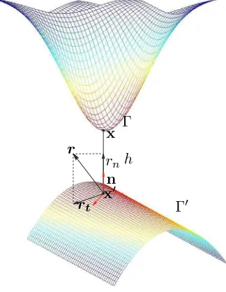
Let us consider two deformable bodies in potential contact and two potential contact surfaces are noted Γand Γ0. Letx=ϕ(X,t)be the current position vector at an instantt ∈It. The orthogonal projection ofxon the body surfaceΓ0is defined
by x0. The contact distance vector (or gap vector) is defined by
g=x−x0 =hn. (1) his the oriented contact distance (Figure 1). The displacement vectoru, the velocity
vector u˙ and the contact stress vectorrcan be uniquely decomposed into a normal
part and a tangential part as follows (Figure 1):
u=ut+unn, un=u·n, (2)
˙
u= ˙ut+ ˙unn, u˙n= ˙u·n, (3) r=rt+rnn, rn=r·n. (4)
non-Γ
Γ0
n x0 x
h rn r
[image:3.612.200.362.7.216.2]rt
Figure 1. Description of contact problem
penetration, a static condition of no-adhesion and a mechanical complementary condition. These three conditions, known as the Signorini conditions, can be for-mulated as
h ≥0, rn≥0, h rn= 0. (5)
In general, at any time t∈It, the potential contact surfacesΓcan be split into two
disjoint parts: +Γ where the body is in contact with Γ0 and −Γ where the body is
separated from Γ0. In the case of dynamic contact, the Signorini conditions can be
formulated, on +Γ, via the relative velocity
˙
un≥0, rn≥0, u˙nrn= 0 on +Γ. (6)
The bodies are separating when u˙n>0 and remain in contact foru˙n= 0.
The formulation (6) of the Signorini conditions can be combined with the sliding rule to derive the complete frictional contact law for the contacting part +Γ. This complete law specifies possible velocities of bodies that satisfy the unilateral contact conditions and the sliding rule. In this work, the classical isotropic Coulomb friction rule is used. The set of admissible forces, denoted by the Coulomb’s convex cone Kµ, is defined by
Kµ=
r∈ R3 such that |rt| −µrn≤0 (7)
can be used to write it in a compact form:
if rn= 0 thenu˙n≥0 ! separating elseifr∈intKµ thenu˙n= 0 and −u˙t=0 ! sticking
else (r∈bdKµ and rn >0)
˙
un= 0 and ∃ λ >˙ 0 such that −u˙t= ˙λ rt |rt|
! sliding endif
(8)
where “intKµ” and “bdKµ” denote the interior and the boundary of Kµ, respec-tively.
It is noted that the minus sign beforeu˙tmeans that the frictional force is opposite
to the sliding velocity in the isotropic friction case. The complete form of the fric-tional contact law involves three possible states, which are separating, contact with sticking, and contact with sliding. Only the last state produces energy dissipation.
2.1.2 Numerical solution
The numerical treatment of the contact constraints is based on two main strate-gies: the penalty method and regularisation methods (Lagrange multipliers). Both approaches have their advantages and their drawbacks. These methods can be easily implemented in an existing finite element code but the choice of good parameters is often difficult (Chamoret et al. (2004)).
In this paper, we have chosen to use an original approach, the bi-potential method. De Saxcé and Feng (De Saxcé and Feng (1998)) have shown that the contact law (8) is equivalent to the following differential inclusion:
−u˙t−( ˙un+µ| −u˙t|)n
∈∂[
Kµ
r where [ Kµ
(r) =
0 if r∈Kµ
+∞ otherwise. (9)
Then, the following contact bi-potential can be defined:
bc(−u˙,r) =
[
R −
(−u˙n) +
[
Kµ
(r) +µ rn| −u˙t| (10)
In order to avoid non-differentiable potentials that occur in nonlinear mechanics, such as in contact problems, it is convenient to use the Augmented Lagrangian Method (Alart and Curnier (1991); Simo and Laursen (1992)). For the contact bi-potential bc, given by (10), the modified augmented surface traction τ is defined
by
τ =r+% −u˙t−( ˙un+µ| −u˙t|)n. (11)
where % > 0 is a numerical parameter which is determined to ensure numerical convergence. It can be shown that r is the projection of τ onto the closed convex
Coulomb’s cone:
r=proj(τ, Kµ). (12)
2.2 Anisotropic hyperelastic constitutive law
2.2.1 Anisotropic hyperelasticity
To investigate internal deformation and stress of biological soft tissues such as ligaments, tendons or arterial walls, anisotropic hyperelastic constitutive laws are often used in the framework of finite element analysis (Weiss et al. (1996); Almeida and Spilker (1998); Rüter and Stein (2000)). The most used strain-energy functions take a power law form (Schröder et al. (2005)) or present an exponential behavior (Fung et al. (1979); Holzapfel et al. (2000)). More recently, Balzani et al. (Balzani et al. (2006)) have proposed polyconvex strain energy functions combining an ex-ponential form with a power law to take care of the tissues behavior in the low load domain. More realistic models have been also recently developed to capture the inter-fiber angle change by adding to the strain energy the contribution of the fiber-matrix shear interaction (Peng et al. (2006)). In general, the anisotropy can be represented via the introduction of a so-called structural tensor, which allows a coordinate-invariant formulation on the constitutive equations (Spencer (1987); Boehler (1987); Zheng and Spencer (1993)). It is usually assumed that anisotropy is due to the collagen fibers behavior (Gasser et al. (2006)), while the ground sub-stance, or matrix, behaves in an isotropic manner, so the energy densities modelling transversely isotropic and orthotropic soft tissues are separated into isotropic and anisotropic parts Weiss et al. (1996); Balzani et al. (2006)
W =Wiso+ n
X
a=1
Wania (13)
Each anisotropic density Wania refers to a preferred direction of the material. The number of fiber families n is generally set to 1 to model tissues as ligaments or tendons while it is set to 2to represent the behaviour of arterial walls.
In the continuation, C = FTF is the right Cauchy-Green deformation tensor
and F the transformation gradient defined by
F = ∂x
∂X =I+
∂u
∂X, J =det(F)>0 (14) X,x and u represent respectively the reference and the current positions and the
displacement vector of a material point.
According to Zhang-Rychlewski’s theorem (Zhang and Rychlewski (1990)), the condition of material symmetry is satisfied if structural tensors are additionally included in the strain energy density representation. Transversely isotropic densities can then be expressed with the three invariants I1,I2 andI3 of the right
Cauchy-Green deformation tensorCand two additional mixed invariantsJ4andJ5(Spencer
(1987); Boehler (1987); Zheng and Spencer (1993))
I1 = tr(C), I2 = tr((cof(C))), I3 = det(C)
J4 = tr(CM), J5= tr(C2M) (15)
where cof(C) denotes the co-factor matrix of C and M is the so-called struc-tural tensor representing the transverse-isotropy group and referring to a preferred direction a of the material
It is noted that (15) and (16) give
J4 = tr FTF a⊗a =kF ak2 (17)
The double brackets represent the usual Euclidian norm. The square root of J4
represents thus the stretch in the fiber direction.
In the case of hyperelastic materials, there exists an elastic potential functionW which is a scalar function of the strain tensors. The second Piola-Kirchhoff stress tensor S and the corresponding Cauchy stress tensor σ are given by
S = ∂W
∂E = 2
∂W
∂C , σ=
1 JF S F
T (18)
In this relation, E is the Green-Lagrangian strain tensor given by the classical
relation:
E= 1
2(C −I) (19)
where I is the second order unit tensor.
To uncouple the deviatoric part to the dilatational part of the response, the volume preserving part F = J−1/3F of the deformation is introduced (Weiss et
al. (1996)). The modified invariants related to C =FTF =J−2/3C are expressed
from (15) by
I1=I1I3−1/3 I2 =I2I3−2/3
Ja4 =J4aI3−1/3 Ja5 =J5aI3−2/3
(20)
The exponential type HGO density adopted in this work uses these modified in-variants as follows
W =W(I1, Ja4) +U(J) (21)
U(J) = k
2(J −1)
2; W(I
1, Ja4) =Wiso(I1) + 2 X
a=1
Wani(Ja4); Wiso(I1) =c1(I1−3)
(22) J4a<1 :Wani(J
a
4) = 0 (23)
J4a≥1 :Wani(Ja4) =
k1
2k2 h
expk2(Ja4−1) 2
−1i (24)
The anisotropic energy density Wani is case sensitive with respect to J4 because
the case of J4 < 1 represents the shortening of the fibers which is assumed to
generate no stress. The proof of convexity of (23)-(24) with respect to F is given
in (Schröder et al. (2005); Peng et al. (2006)). The non-collagenous matrix of the media is modelled by the neo-Hookean isotropic density Wiso defined by (22). It is
dependency on the structural tensor. This is proved recently by Guo et al. (Guo et al. (2008)) where a simple compressible anisotropic analytical model is developed. The c1,k1 and k2 material parameter values have been chosen like in (Balzani et
al. (2006)) in order to fit the model with experimental data: c1 = 10.2069kP a,
k1 = 0.0017kP a, k2 = 882.847. These parameters are assumed to be independent
of the fiber orientation. This hypothesis is consistent since the fiber properties are assumed to be independent of their orientation.
The dilatational component U(J) defined by equation (22) represents a penalty term added to the finite element model to account for the incompressible behaviour of the material. The parameter k was chosen equal to 105. We remind finally that by deriving W from equation (18) and introducing the matrix of cofactors of C,
Cof(C) =I3C−T , it is conventionally obtained
S = 2
∂W ∂I1
I +∂W
∂I2
(I1I−C) +
∂W ∂I3
cof(C) + ∂W
∂ J41
Ma1+ ∂W
∂ J42
Ma2
+ ∂W ∂ J1 5
CMa1+Ma1C+ ∂W
∂ J2 5
CMa2+CMa2
(25)
In our particular case, equation (25) is reduced to:
S = 2
∂W ∂I1
I+∂W
∂I3
cof(C) + ∂W
∂ J1 4
Ma1+ ∂W
∂ J2 4
Ma2
(26)
The derivatives of the density energy W with respect to the invariants are de-scribed in Peyraut et al. (2010). The stress tensor (26) and the first derivatives of the energy density with respect to the invariants will be used to evaluate the tangent modulus. These moduli are useful to implement hyperelastic models in a finite element code. The implementation of the HGO model in the in house FE code FER is presented in the next section.
2.2.2 Finite element implementation of HGO model
The HGO model have been implemented and tested in the finite element code FER/Impact. This code is implemented using C++ object-oriented programming language. In the context of large hyperelastic displacement and rotations, the Green-Lagrangian strain tensor is used to describe the non-linear strain-displacement re-lationship:
E=
BL+1
2BN L(u)
u (27)
where BL is the matrix which relates the linear strain term to the nodal
displace-ments, andBN L(u), the matrix which relates the nonlinear strain term to the nodal
displacements. The incremental form of the strain-displacement relationship is:
δE = BL+BN L(uδu (28)
Using equations (18) and (28) , the incremental form of the stressδS can be linked
to the incremental form of the strain δE as follows:
δS= ∂
2W
∂E2 :δE=D:δE=D: BL+BN L(u)
where D denotes the constitutive tangent matrix. This fourth-order tensor is
ob-tained from the derivative of W (Schröder et al. (2005)). Using the principle of virtual displacement, the virtual work δU is given as
δU =δuTMu¨+δuTAu˙ +
Z
V0
δETSdV −δuTFext−δuTR= 0 (30)
whereV0is the volume of the initial configuration,Fextthe vector of external loads, R the contact reaction vector, M the mass matrix, A the damping matrix,u˙ the
velocity vector and u¨ the acceleration vector.
The damping implemented in the finite element code FER is a Rayleigh damping, it means the damping matrix A is a linear combination of the stiffness and mass
matrix. Substituting (28) into equation (30), we obtain:
δW =δuT
Mu¨+Au˙ +
Z
V0
BL+BN L(u)TSdV0−Fext−R
= 0 (31)
The vector of internal forces is defined by
Fint=
Z
V0
BL+BN L(u)TSdV . (32)
Since δu is arbitrary, it can be deduced from (31)
Mu¨+Au˙ +Fint−Fext−R= 0. (33)
The initial conditions associated with the dynamic equation (33) are: ˙
u= ˙u0 and u=u0 (34)
Dynamic equation (33) can be integrated between time t and t+ ∆t by using an explicit algorithm:
ut+∆t= ∆t2M−1 Ft
ext−Ftint+Rt+∆t
+ 2ut−ut−∆t (35)
It is possible to use special finite elementQ1P0(Scovazzi et al. (2008)) to achieve the element integration by separating the contributions from spherical and devi-atoric stress. However, in the current version of FER, the integration of internal forces is the same as for the spherical and deviatoric parts, using twenty-seven Gauss points for hexahedral elements and only one Gauss point for tetrahedral elements. It should be noted that the contact reactionsRare evaluated with the bi-potential
method presented in Section 2.1. All the approaches presented in Sections 2.1 and 2.2 have been implemented in the finite element code FER.
3. Finite element model
3.1 Creation of the hand model
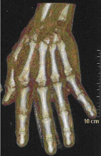
with no relation with the present study. No abnormalities were found by the med-ical staff. The acquisition of the 3D geometry was performed without injection with bidimensional reconstructions. Resolution of 2D slices was 0.7 millimeters. For the reconstruction, almost 300 slices in transversal plane were used. Figure 2 illustrates one CT slice of the hand. In order to distinguish the bones from the
Figure 2. CT slice of the hand
soft tissues, the slices processing was performed by using a grey level processing, using the Scan2Mesh, which is a tool allowing 3D reconstruction, included in the HyperWorks package (Altair c).
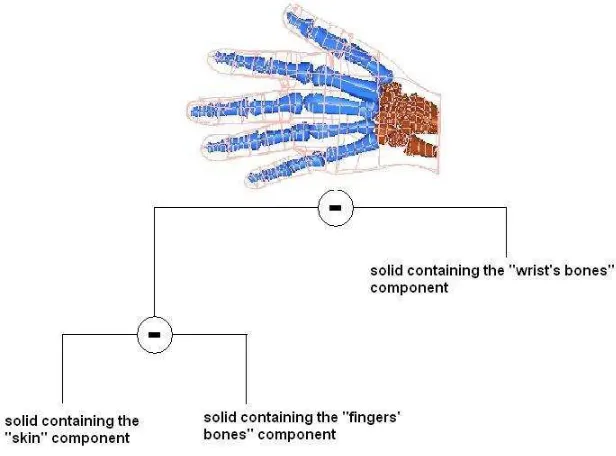
In specifying the space between slices, the size of the pixels in each direction, and the precision of the mesh, a 3D triangular mesh was generated, and imported in HyperMesh v9.0 software (Altair c) for a step of surface reconstructions, as illustrated in figure 3, and a step of 3D meshing as illustrated in Figure 4.
Figure 3. STL meshing of the hand with tria before the reconstruction of the surfaces
[image:9.612.179.388.488.621.2]Figure 4. Surface reconstruction based on STL meshing: wrist and fingers
have been created, and Boolean operations have been used, as presented in Figure 5.
Figure 5. Description of the creation of the mesh
Then an automatic mesh of the three components is performed allowing a con-tinuous mesh (without interfaces) between wrist’s and fingers’ bones and the skin. Finally, the global mesh of the hand has17700 4-node tetra elements shared into: 1700 elements in wrist’s bones,2000 elements in fingers’ bones and14000elements for the skin.
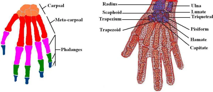
The final mesh of the hand includes (Figure 6):
• 8 bones of the wrist (carpsal): the scaphoid, lunate, triquetral pisiform, trapez-ium, trapezoid, capitate and hamate;
• 5 metacarpsal;
• 14 phalanges : distal phalanges, middle phalanges and proximal phalanges.
3.2 Description the impact problem
[image:10.612.121.429.214.442.2]Figure 6. Final mesh of the hand
interactions very useful to improve design.
Our work consists in setting up a finite model of a hand as biofidelic as pos-sible. The creation of this kind of model needs many investigations and leads to extremely complicated finite element model, generally CPU time consumer. The hand is composed of different components (cartilage, tendons, ligaments, muscles). The influence of these individual components may be essential to the overall re-sponse of the hand. Our model is a first step in the creation of a hand model: no cartilage, no tendons, no ligaments and no muscles are taken into account. Actually, the behaviour of skin and all soft tissues is processed by the HGO model presented in Section 2.2.
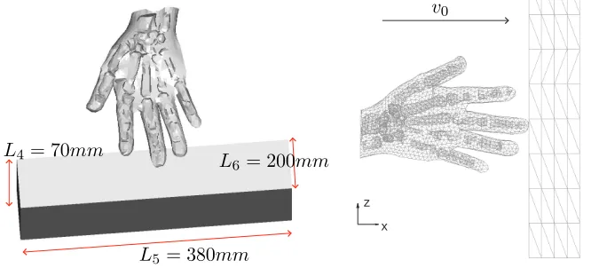
The object is considered as linear elastic. Discrepancies exist concerning the elas-ticity of cortical bone. Age dependency has been demonstrated varying between 10 and15GP a(Rho et al. (1997); Wang et al. (2002); Kemper et al. (2005); Buchanan and Ural (2010)). Wrist and finger’s bones are considered as linear elastic with typ-ical corttyp-ical bones’s properties: E= 10000 M P a,ν = 0.22 andρ= 2150 kg/m3.
The hand sizes correspond toL1 = 159.23mm,L2 = 230.12mmandL3= 77.68
mm (Figure 7) while the block ones are shown in Figure 8. The hand mesh is described in Figure 6 with5794 nodes and17700tetrahedral elements. Besides, the parallelepipedic block has 1040 nodes and4684 tetrahedral elements.
L1
L2
L3
L4= 70mm
L5= 380mm
L6 = 200mm
x z
[image:12.612.108.441.16.167.2]v0
Figure 8. Problem description
3.3 Numerical strategy
The treatment of contact conditions leads to variational inequalities. Various algo-rithms could be employed to solve contact problems. In this paper, we have chosen to use an original approach, the bi-potential method which has been successfully applied for the modelling of frictional contact problems in static cases. This paper presents the application of this method for dynamic analysis of impact problems with friction between an hyperelastic body and an elastic one (Feng et al. (2006)). We want to model an operator’s hand at work, but its movement control depends on the rigidity of the hand gesture. We assume that the hand manipulates the block using an initial speed equal to v0 = 2m/s in x direction (Figure 8). The transient
dynamic calculation is managed by an explicit scheme shown in Section 2.2.2 to cut down computational cost. This choice is justified by the highly nonlinear feature of the case, as it deals with the dynamic contact and impact in 3D anisotropic hy-perelasticity. The explicit resolution of contact problem is much more efficient than the implicit one because it is well adapted to speed and acceleration discontinuities when a sudden contact status change occurs. Accordingly, the decision of using an explicit contact FE model appears rational.
It has been shown that non-linearity can cause divergence using an implicit finite element code (Horii et al. (1993)). An explicit analysis requires the identification of a critical time step to ensure the stability of the temporal scheme (Newmark (1959)). This critical time step is related to the characteristic element size and material properties. A critical value can be defined as the time required such that the pressure wave travels through only one elastic element:
∆t=
r
ρ
ELmin (36)
Lmin is the characteristic dimension of the smallest mesh element,ρ is the density
and E the Young’s modulus. The magnitude ofLmin is 10−5m in the case of this
study. A time step has been chosen approximatively equal to 10−7s. The analysis
was carried out using the finite element code FER.
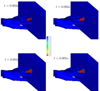
Figure 9. Von Mises stress
3.4 Results
Figure 10 shows the evolution over time of the Von Mises stress at different steps of computation : t= 0.002s,t= 0.003s,t= 0.004s,t= 0.005s. Since stresses begin in the contact areas between the hand and the block, it is possible to track the spread of the contact areas during the time.
t= 0.002s t= 0.003s
t= 0.004s t= 0.005s
[image:13.612.111.449.351.660.2]4. Discussion and future work
Our main interest is to develop a model that can describe hand motion during reach and grasp. Many grasping models have been already developed but none of them use a 3D total deformable hand model (Carbone and González (2011); Bae and Armstrong (2011); Kim et al. (2009)). We have chosen to use the finite element method to model these phenomena. This is a big challenge for two main reasons. From a mechanical point of view, multiples nonlinearities must be taking into ac-count: geometrical, material, frictional contact and impact. From a biomechanical point of view, a perfect knowledge of the hand must be known.
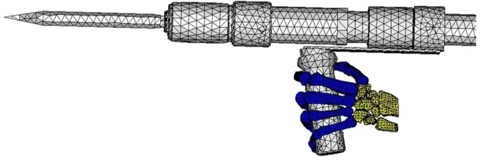
[image:14.612.108.459.353.473.2]In fact, this model is just a first step to create a more realistic hand model. The main purpose of this paper is to validate a process from CT scan to a 3D finite element model and then to perform a simulation on this model including nonlinear phenomena such as contact and hyperelasticity. It is not focused on the detailed structures of the hand. In any case, no one can obtain a 100% numerical model regarding the complexity of the hand. The proposed model is simplistic from the biomechanical point of view, but from a mechanical point of view and for the considered case study, the cartilage, tendons, ligaments and muscles do not play an important role and can reasonably be neglected. The next step of our work which will consist in biomechanical developments to model the movements of reaching and grasping. The idea is to combine soft tissue with appropriate comportment law (Evans (2009); Natali et al. (2006)) and an articulated model for the skeleton. Figure 11 shows the first evolution of the model with an example of movement of grasping tool. This model takes into account ligaments modelled as springs and the use of anisotropic hyperelasticity is the next step.
Figure 11. Work in progress: movements of grasping
5. Conclusion
code FER. These implementations are detailed in the paper. To demonstrate the efficiency of FER to deal with the non linear topics considered in this paper, a numerical example is presented. This example concerns the contact/impact of an human hand on a deformable rectangular block. The modelling of the hand includes the bones and the soft tissues behaviours. Our work paves the way to modelling surgery environment by using FE simulation. However, including such model in the context of virtual reality (for example to train surgeons to good practise and ade-quate gestures) is still a challenging task as the computation time does not meet the requirement for real-time application. Contact detection in a reduced basis (gener-ally used by model reduction techniques to drastic(gener-ally save computation time) is also an another open issue.
References
Alart P, Curnier A. 1991. A mixed formulation for frictional contact problems prone to Newton like solution methods. Computer Methods in Applied Mechanics and Engineering 92(3):353 – 375.
Almeida ES, Spilker RL. 1998. Finite element formulations for hyperelastic transversely isotropic biphasic soft tissues. Computer Methods in Applied Mechanics and Engineering 151(3-4):513 – 538. Contain-ing papers presented at the Symposium on Advances in Computational Mechanics
Bae S, Armstrong TJ. 2011. A finger motion model for reach and grasp. International Journal of Industrial Ergonomics 41(1):79 – 89.
Balzani D, Neff P, Schröder J, Holzapfel GA. 2006. A polyconvex framework for soft biological tissues. Adjustment to experimental data. International Journal of Solids and Structures 43(20):6052 – 6070. Boehler JP. 1987. “Introduction to the invariant formulation of anisotropic constitutive equations,”
Appli-cations of Tensor Functions in Solids Mechanics, CISM Course No. 292. Springer Verlag.
Buchanan D, Ural A. 2010. ASME; Finite Element Modeling of the Influence of Hand Position and Bone Properties on the Colles’ Fracture Load During a Fall. Journal of Biomechanical Engineering 132(8), 081007.
Carbone G, González A. 2011. Tarrytown, NY, USA: Pergamon Press, Inc.; A numerical simulation of the grasp operation by LARM Hand IV: A three finger robotic hand. Robot. Comput.-Integr. Manuf. 27:450–459.
Chamoret D, Saillard P, Rassineux A, Bergheau JM. 2004. New smoothing procedures in contact mechanics. Journal of Computational and Applied Mathematics 168(1-2):107 – 116. Selected Papers from the Second International Conference on Advanced Computational Methods in Engineering (ACOMEN 2002)
De Saxcé G, Feng ZQ. 1998. The bipotential method : A constructive approach to design the complete contact law with friction and improved numerical algorithms. Mathematical and computer modelling 28(4–8):225–245.
Evans SL. 2009. Taylor & Francis; On the implementation of a wrinkling, hyperelastic membrane model for skin and other materials. Computer Methods in Biomechanics and Biomedical Engineering 12(3):319– 332.
Feng ZQ, Peyraut F, He QC. 2006. Finite deformations of Ogden’s materials under impact loading. Inter-national Journal of Non-Linear Mechanics 41(4):575 – 585.
Feng ZQ, Zei M, Joli P. 2007. An elasto-plastic contact model applied to nanoindentation. Computational Materials Science 38(4):807 – 813.
Fung YC, Fronek K, Patitucci P. 1979. Pseudoelasticity of arteries and the choice of its mathematical expression. Am J Physiol Heart Circ Physiol 237(5):H620–631.
Gasser TC, Ogden RW, Holzapfel GA. 2006. Hyperelastic modelling of arterial layers with distributed collagen fibre orientations. J R Soc Interface 3(6):15–35.
Guo ZY, Caner F, Peng XQ, Moran B. 2008. On constitutive modelling of porous neo-Hookean composites. Journal of the Mechanics and Physics of Solids 56(6):2338 – 2357.
Holzapfel GA, Gasser TC, Ogden RW. 2000. A New Constitutive Framework for Arterial Wall Mechanics and a Comparative Study of Material Models. Journal of Elasticity 61(1):1–48.
Horii E, An KN, Linscheid RL. 1993. Excursion of prime wrist tendons. The Journal of Hand Surgery 18(1):83 – 90.
Joli P, Feng ZQ. 2008. Uzawa and Newton algorithms to solve frictional contact problems within the bi-potential framework. Int. J. Numer. Meth. Engng. 73:317–330.
Kemper AR, McNally C, Kennedy EA, Manoogian SJ, Rath AL, Ng TP, Stitzel JD, Smith EP, Duma SM, Matsuoka F. 2005. Material properties of human rib cortical bone from dynamic tension coupon testing. Stapp car crash journal 49:199–230.
Kim Y, Choi J, Park J. 2009. Physically based grasping and manipulation method using pre-contact grasping quality measureIn:Proceedings of the 16th ACM Symposium on Virtual Reality Software and Technology. Kyoto, Japan. VRST ’09. New York, NY, USA: ACM. pp. 253–254.
Misraa S, Rameshb KT, Okamurab AM. 2011. Modelling of non-linear elastic tissues for surgical simulation. Computer Methods in Biomechanics and Biomedical Engineering pp. 811–818.
Natali A, Carniel E, Pavan P, Dario P, Izzo I. 2006. Hyperelastic models for the analysis of soft tissue mechanics: definition of constitutive parametersIn: . Feb.. pp. 188–191.
Me-chanics Division, ASCE .
Peng XQ, Guo ZY, Moran B. 2006. ASME; An Anisotropic Hyperelastic Constitutive Model With Fiber-Matrix Shear Interaction for the Human Annulus Fibrosus. Journal of Applied Mechanics 73(5):815– 824.
Peyraut F, Chamoret D, Gomes S, Feng ZQ. 2010. Implémentation éléments finis du modèle hyperélastique anisotrope HGO.. European Journal of Computational Mechanics . A paraître.
Rho JY, Tsui TY, Pharr GM. 1997. Elastic properties of human cortical and trabecular lamellar bone measured by nanoindentation. Biomaterials 18(20):1325 – 1330.
Rüter M, Stein E. 2000. Analysis, finite element computation and error estimation in transversely isotropic nearly incompressible finite elasticity. Computer Methods in Applied Mechanics and Engineering 190(5-7):519 – 541.
Schröder J, Neff P, Balzani D. 2005. A variational approach for materially stable anisotropic hyperelasticity. International Journal of Solids and Structures 42(15):4352 – 4371.
Scovazzi G, Love E, Shashkov MJ. 2008. Multi-scale Lagrangian shock hydrodynamics on Q1/P0 finite elements: Theoretical framework and two-dimensional computations. Computer Methods in Applied Mechanics and Engineering 197(9-12):1056 – 1079.
Simo JC, Laursen TA. 1992. An augmented lagrangian treatment of contact problems involving friction. Computers&Structures 42(1):97 – 116.
Spencer AJM. 1987. “Isotropic polynomial invariants and tensor functions,” Applications of Tensor Func-tions in Solids Mechanics, CISM Course No. 292. Springer Verlag.
Thalmann NM, Thalmann D. 1995. Finite elements in task-level animation. Finite Elements in Analysis and Design 19(4):227 – 242.
Wang X, Shen X, Li X, Agrawal CM. 2002. Age-related changes in the collagen network and toughness of bone. Bone 31(1):1 – 7.
Weiss JA, Maker BN, Govindjee S. 1996. Finite element implementation of incompressible, transversely isotropic hyperelasticity. Computer Methods in Applied Mechanics and Engineering 135(1-2):107 – 128.
Zhang JM, Rychlewski J. 1990. Structural tensors for anisotropic solids. Arch. Mech. 42:267–277. Zheng QS, Spencer AJM. 1993. Tensors which characterize anisotropies. International Journal of