viability of the technique for spectral amplitude coded OCDMA and show that the benefits of SOA-based noise suppression do not extend readily to this application due to post-SOA optical-filtering effects at the receiver. However, appreciable performance improvements can in principle be realized through optimized system and decoder design.
Index Terms—Optical code division multiple access (OCDMA), optical noise, semiconductor optical amplifier (SOA).
I. INTRODUCTION
O
PTICAL code division multiple access (OCDMA) has been proposed as a potential solution to address the bandwidth and flexibility demands of local area and access networks [1]. OCDMA allows statistical multiplexing [2] and asynchronous operation, while giving service providers the ability to offer service differentiation [3], highly desir-able for last-mile end-user markets. While numerous im-plementations of OCDMA have been investigated [1]–[6], spectral-amplitude-coded (SAC) techniques using inexpensive broadband sources are well suited for the cost-sensitive access environment [6].In CDMA, each user channel is assigned a unique code signature, which is imprinted onto the data signal prior to trans-mission. SAC OCDMA systems employ passive optical filters to encode this channel signature as a sequence of spectral slices or “chips.” At the receiver, an individual channel is selected by performing a correlation between the incoming encoded signal and the code sequence, such that a peak in the correlation sig-nifies the desired channel. For accurate detection, the channel code sequence should have a high autocorrelation while retain-ing low cross correlation with the other interferretain-ing channels. When used with suitable codes, balanced differential detection in a SAC OCDMA receiver can effectively suppress multiple-access interference (MAI) [6]. However, systems employing
Manuscript received July 14, 2006; revised September 12, 2006.
A. D. McCoy, M. Ibsen, P. Horak, and D. J. Richardson are with the Optoelectronics Research Centre, University of Southampton, SO17 1BJ Southampton, U.K.
B. C. Thomsen was with the Optoelectronics Research Centre, University of Southampton, SO17 1BJ Southampton, U.K. He is now with the Department of Electronic and Electrical Engineering, University College London, WC1E 7JE London, U.K.
Digital Object Identifier 10.1109/JLT.2006.886678
system capacity [8].
Beat-noise reduction in SAC OCDMA systems has been investigated by a number of groups [9]–[11] who have focused on developing code families with minimal in-phase cross cor-relation between channels in order to reduce the total amount of interchannel beating at each detector. This is achieved by generating codes with reduced weight (the number of “ones” in each code sequence) relative to code length. However, at the same received power level, lower weight spectral codes give rise to reduced signal quality, since the intensity noise increases inversely with channel bandwidth [7]. As such, it is of interest to reduce this intensity noise in order to improve the signal quality of each channel prior to transmission. The system impact caused by the interchannel beat noise would also be reduced in this case, and when used in conjunction with the appropriate family of low cross-correlation codes, the system performance could be further enhanced.
A semiconductor optical amplifier (SOA) operating in gain saturation can be used to suppress optical intensity noise and has been proposed for use in spectrum slicing, providing signif-icant “intensity smoothing” of noisy light [12]. The technique suppresses noise fluctuations over several gigahertz, while the wide gain bandwidth of the amplifier can accommodate in-tensity smoothing over a large optical frequency span. Addi-tionally, the SOA has potential to be used for simultaneous noise suppression and modulation and can be monolithically integrated alongside other devices, allowing a compact solution for access markets. We therefore investigated this technique as a means to suppress per-channel noise in a SAC OCDMA system. Despite the benefits listed above, in the course of our re-search, we found that the superior signal quality offered by the saturated SOA was noticeably degraded by subsequent optical filtering, leading to a tangential investigation into these effects [13]. Spectral filtering at the receiver is an unavoidable part of SAC and thus places severe limits on the partnership of the two technologies. In this paper, we summarize our studies in this area and discuss the feasibility of SOA-based noise suppression for SAC OCDMA applications in light of the implications of post-SOA filtering. Given the ramifications of this study, we expect that a summary of our investigation would benefit other researchers, who may also seek to extend the advantages of SOA-based intensity noise suppression from spectrum slicing to SAC OCDMA.
Fig. 1. Two-channel block diagram for SOA per-code experiments. Noise-suppression block shown in Fig. 2. PC: Polarization controller. EOM: Electrooptic modulator. BPF: Bandpass filter. The spectral response of the code filters is given in Fig. 3.
This paper is organized as follows: In Section II, we out-line our proof-of-concept SAC OCDMA experiment where we employ an SOA per code/channel. We compare the system performance with and without noise suppression and discuss the observed effects. In Section III, possible optimizations are investigated in an attempt to reduce the filtering effects. The conclusions of the study are given in Section IV.
II. SOAPERCODE
A. Experiment
When a saturated SOA is used to amplify a modulated signal, the transient response of the SOA gain can produce patterning effects that give rise to significant eye distortion [14]. Consequently, our strategy was to use the SOA to suppress the intensity noise of an individual channel prior to modulation. A two-channel system was implemented, largely following that outlined in [6], but with a saturated SOA added to each transmitter for noise suppression.
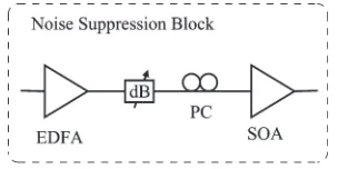
The experimental setup is shown in Fig. 1. The ASE from an erbium-doped fiber amplifier (EDFA) is split to form the source spectra for the two channels, which are then shaped by fiber Bragg grating (FBG) filters Code Tx1 and Tx2 which imprint the channel signature onto the optical spectrum. The FBG filters used to perform the spectral encoding and decoding operations were fabricated in-house [15]. Each code filter consisted of two apodized uniform gratings cascaded in series with a sep-aration of approximately 1 mm. Encoding the signal prior to modulation avoids pulse broadening that arises from the spatial separation of the two grating segments in the cascaded array [10]. As shown in Fig. 1, the encoder filters were followed by a noise-suppression block (Fig. 2) which consisted of a booster EDFA, a variable attenuator, a polarization controller, and an SOA. After the SOA, each channel was modulated at 622 Mb/s (pattern length27−1), using a LiNbO3electrooptic modulator.
The channel powers were balanced at the output of the second 3-dB coupler, while the bandpass filter was used to remove the out-of-band ASE introduced by the SOA.
At the decoder, another grating filter (Code Rx1a) performs a correlation function between the incoming signal and the
Fig. 2. Noise-suppression block.
desired user code. A second decoder filter (Code Rx1b), which is a spatially reversed copy of Code Rx1a, is used to remove the pulse broadening introduced by the grating cascade. The frequency response of the reflection path matches the code signature of the desired channel (i.e., channel 1 in this case), while the transmission-path response is the complement of the reflection spectrum. Thus, the output from the transmission path represents the correlation between the received signal and the complement of the channel code sequence. The variable attenuator was used to balance the unmatched channel power in both arms of the decoder, while a variable delay line was used to equalize the path lengths and ensure simultaneous arrival of data bits at the inputs of the 800-MHz balanced differential receiver. The two-channel system performance (i.e., Q-factor) was assessed using a sampling oscilloscope with a 622-Mb/s receiver module. We also characterized the relative intensity noise (RIN) of the continuous-wave (CW) light (i.e., bypassing the modulators), since, unlikeQmeasurements, this provides a direct assessment of the intensity noise in the optical signal without the need to consider modulation effects. All RIN measurements were performed at 100 MHz using a low noise 125-MHz photoreceiver and electrical spectrum analyzer at an optical power level of−15 dBm.
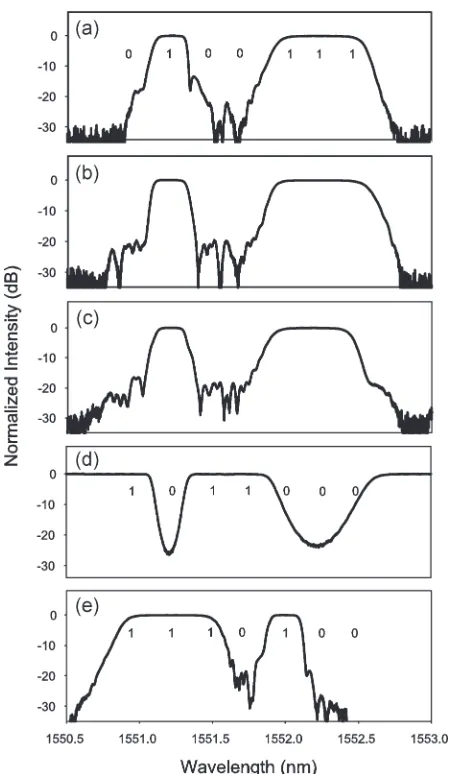
[image:2.594.350.502.275.351.2]Fig. 3. Grating spectra for matched and unmatched code gratings. Matched channel{0,1,0,0,1,1,1}: (a) Code Tx1 in reflection, (b) Code Rx1a in reflection, (c) Code Rx1b in reflection, and (d) Code Rx1a in transmission. Unmatched channel{1,1,1,0,1,0,0}: (e) Code Tx2 in reflection. The place-ment of these gratings within the system is shown in Fig. 1.
The signature codes used in this paper are based on cyclic shifts of a single seven-chip m-sequence, {0,1,0,0,1,1,1}, which has the requisite correlation properties for perfect channel orthogonality when used in conjunction with bal-anced detection [6]. Each code has a weight of 4, with two chips overlapping between each pair of users. Code 1
{0,1,0,0,1,1,1} was used for the subject channel while Code 2 {1,1,1,0,1,0,0} formed the interfering channel, which are also referred to as the matched and unmatched channels, respectively.
The FBG code filters were specified with a chip spacing of 0.25 nm and a 3-dB bandwidth of 0.23 nm, giving two passbands of approximately 0.23 and 0.7 nm with identical reflectivities of ∼99.5% for the two cascaded gratings. The measured spectral response of the code filters is given in Fig. 3. Each grating array was placed in a tunable mount which enabled strain tuning of the code filters, facilitating wavelength alignment between the encoder and decoder gratings. The tun-able mount did not, however, permit tuning of individual chips in the code.
eye at the receiver.
For the unmatched channel, the reflection and transmission paths each block two chips from the code, giving approximately equal power at both inputs to the balanced detector. Fig. 4(c) and (d) show complete eye closure when only the unmatched channel is transmitted, indicating that cross-talk power from channel 2 is well suppressed. Note, however, that the intensity noise on both of the “closed” eye diagrams shows no apprecia-ble difference, indicating that intensity noise was not effectively suppressed in this case. We also see that when both channels are transmitted simultaneously, the noise suppression does not pro-duce any noticeable advantage; the eye quality degrades notice-ably over the single matched channel, andQapproaches that of the two-channel system with no noise suppression(Q= 3.7).
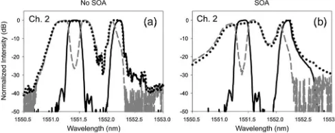
We also observed that the saturated SOA introduced substan-tial distortion to the encoded spectrum, as shown in Figs. 5 and 6. The signal spectrum is broadened, and the peak spectral density is shifted toward longer wavelengths (a red shift). Subsequently, this distorted spectrum is filtered by the decoder gratings at the receiver. Note that the unmatched channel experiences much greater spectral alteration than the matched channel, as in this case, half of the encoded spectrum is filtered out in each arm of the differential receiver [Fig. 6(b)].
As the main difference between the two received channels is the extent of decoder filtering, the eye diagrams above sug-gested that the signal quality of the “intensity-smoothed” light was degraded by optical filtering. Despite the effective mitiga-tion of MAI through balanced detecmitiga-tion, the spectral filtering at the decoder increases the noise in the unmatched channel, rendering it comparable in quality to the original signal without noise suppression. As in the pure thermal-light scenario, system performance is limited by beat noise at the detector.
These filtering effects are more clearly illustrated using a simple characterization experiment [see Fig. 7(a)]. In this case, the “encoding” filter is a simple spectral slice (0.24-nm 3-dB bandwidth), as given in Fig. 7(b). After noise suppression by the saturated SOA, the broadened slice is optically filtered at the receiver with “decoder” filters of varying bandwidths.
Fig. 4. SOA per-code experiments: Eye diagrams are shown for (a) without and (b) with noise suppression for a single matched channel, (c) without and (d) with noise suppression for a single unmatched channel, and (e) without and (f) with noise suppression for the 622-Mb/s two-channel system. For the matched channel, the SOA improves theQfrom 5.5 to 7.2, while no change is observed for the two-channel system(Q= 3.7).
Fig. 5. Spectra at the decoder input (dots), decoder reflection path (black solid), and transmission path (gray dashes) for (a) matched channel only without SOA and (b) matched channel only with SOA.
Fig. 6. Spectra at the decoder input (dots), decoder reflection path (black solid), and transmission path (gray dashes) for (a) unmatched channel only without SOA and (b) unmatched channel only with SOA.
the same trend. A comprehensive study into post-SOA spectral filtering effects is given in [13].
Returning to the SAC OCDMA experiment of Fig. 1, the measured RIN values at the SOA input, output, and decoder path outputs are shown in Table I. Simulation results for channel 1 are also given and were obtained using a traveling-wave SOA model based on the amplifier carrier density and field equations as described in [16]. As expected, simulation values show good agreement with the experiment. It is clear that the saturated SOA provides a substantial reduction in the intensity noise of the thermal-light input, improving the signal quality by ∼20 dB. The intensity noise level noticeably
in-creases after the decoder due to the post-SOA filtering effects discussed above. The matched-channel noise contribution from the transmission path is negligible due to the very low power level. However, the noise on the unmatched channel is the cumulative noise from both detectors of the differential re-ceiver, and thus, the saturated SOA provides little benefit in this case, as is apparent from the measured RIN. Also, note that although the unmatched channel power is evenly balanced between the two inputs of the receiver, the degree of filtering is somewhat unequal. The imbalance arises from the asymmetric red shift introduced by the saturated SOA, as well as the slight mismatch in filter response between the encoding and decoding gratings; this explains the observed difference in RIN between the decoder reflection and transmission paths for the unmatched channel. The observed spectral distortion of the transmitted signal could in principal be avoided by moving the noise-suppression block ahead of the encoder. However, any noise suppression provided by the SOA in this configuration would be diminished by the encoder-filtering process, providing neg-ligible overall benefit.
Qualitatively, the signal degradation caused by post-SOA optical filtering can be explained by considering the nonlinear interactions that take place within the saturated amplifier. The gain compression that occurs in saturation acts across the entire gain bandwidth of the SOA and introduces correlations between the intensity noise of the various spectral components propagat-ing through the amplifier. We have shown both experimentally and via simulations [13] that in distinct contrast to thermal light (e.g., the SOA-input light), anticorrelations exist between the intensity noise of different spectral components, which in turn yield reduced fluctuations in the total output intensity (i.e., noise suppression). Subsequent optical filtering removes frequency components that contribute to the intensity smooth-ing, thereby counteracting the noise suppression introduced by the saturated SOA.
[image:4.594.39.283.472.569.2]Fig. 7. (a) Single channel performance characterization with simple encoding and decoding filters. (b) Encoder-filter spectral response (solid) and broadened SOA output (dashed). (c)Qat 622 Mb/s as a function of post-SOA filter bandwidth. Decoder filters are of the same spectral shape as the encoding filter. The input power to the detector was held constant for all filters.
TABLE I
SINGLE-CHANNELRINFORSOAPER-CODEEXPERIMENTS
in the decoding process. In a practical multichannel SAC OCDMA system, the total noise contribution from the many interfering channels would outweigh the improvement to the matched channel, minimizing the advantage of this approach. Furthermore, any phenomenon that alters the correlations between the spectral components of the intensity-smoothed light (e.g., dispersion) can also lead to additional signal degradation [13], [17].
III. MINIMIZINGSPECTRALFILTERING
It is clear that if SOA-based noise suppression is to provide a significant performance enhancement in SAC OCDMA ap-plications, post-SOA spectral filtering effects must be greatly reduced. This can be accomplished at the system level by restructuring the encoder to employ an individual SOA for each spectral chip and then composing the code sequences by coupling together the intensity-smoothed chips. In this con-figuration, the decoding process does not drastically alter the distinct output spectrum of any individual SOA. Clearly, as an engineering solution, this is impractical for any realistic code length and channel count. However, our goal was to assess the upper limits on the performance of SOA-based noise
suppression in SAC OCDMA systems. In keeping with this, a brief study was undertaken as described below.
For this investigation, the code sequence and decoder config-uration were retained from the previous experiment (Section II), while new encoding filters were required at the transmitter. The encoder gratings were fabricated as “single-chip” grating struc-tures, with a 3-dB bandwidth of 0.24 nm and spectral response as given in Fig. 7(b) (a representative SOA-output spectrum is also shown). After intensity smoothing by individual SOAs, the encoder chips at the different wavelengths were combined to form the two separate codes; the chip spacing was 0.25 nm as before. The channels were then individually modulated at 622 Mb/s, after which they were multiplexed together using a 3-dB coupler prior to transmission. The decoded signal was assessed using a sampling oscilloscope and a 622-Mb/s receiver module. As before, the operating point of each SOA was optimized for best noise suppression. In this system configu-ration, the input polarization of each SOA had to be optimized concurrently with balancing the power and modulation depth across all spectral chips to obtain an accurate evaluation of the two-channel system performance.
We found that the intensity fluctuations on both the ones and zeros were observably lower when incorporating the SOAs, andQincreased from 3.7 to∼5 relative to the SOA per code system. This improvement is attributed to the reduced post-SOA spectral filtering achieved by using an individual post-SOA for each chip.
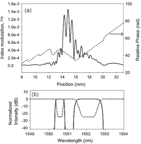
Fig. 8. (a) Spatial design of the optimized superstructure decoder grating. The amplitude and phase of the index modulation are given by the solid and dotted lines, respectively. (b) Grating reflection (solid line) and transmission (dotted) spectra.
A further advantage can be gained if the cascaded grating structure used in the previous decoder is replaced by a single superstructured grating [15], eliminating the need for two FBGs at the decoder and reducing unnecessary optical filtering.
We have investigated via simulations the potential signal-quality improvement offered by such an optimized decoder grating. Commercial grating-design software from Attolight Corporation was used to design a superstructured FBG tailored to the requirements given above. The software implements a full time-domain layer-peeling algorithm [18] and gives the index-modulation profile |δn| to be imprinted onto the fiber. The interchip spacing was increased from 0.25 to 0.38 nm to compensate for the spectral broadening introduced by the SOA; the maximum chip spacing was limited to the tuning range of our encoder gratings. A transmission extinction of 25 dB and zero dispersion were specified to meet the strong reflectivity and minimal pulse-broadening constraints, respec-tively. By designing the grating for zero dispersion, the second FBG at the decoder can be eliminated. The spatial design of the superstructured FBG is shown in Fig. 8(a); |δn| has a maximum value of approximately1.4 × 10−3, which is within
the capabilities of our in-house grating writing facility [19]. The spectral response of the new grating design is given in Fig. 8(b). Using the SOA model, we calculated the RIN values at the differential receiver inputs (i.e., decoder output paths) for the SOA per-chip configuration described above. Results are given in Table II. Simulation results are also shown for the decoder-input spectra when transmitting channels 1 and 2 individually (see Fig. 9); superimposed on this plot is the spectral response of the new decoder-grating design. It is important to note here that in designing the optimum grating, a tradeoff must be made between reducing post-SOA spectral filtering and minimizing crosstalk from undesired chips.
TABLE II
[image:6.594.344.506.86.134.2]DECODEROUTPUTRIN WITHOPTIMIZEDDECODER
Fig. 9. Two-channel decoder-input spectrum for SOA per-chip system (matched channel: solid line; unmatched channel: dashed line) and superstruc-tured grating design reflection spectrum (dots). A tradeoff must be made in terms of minimizing the filtering effects while also minimizing the crosstalk power from unwanted chips.
We can see from Table II that a substantial signal-quality enhancement is achieved over the previous SOA per-code ex-periments (compare with Table I) when using the new sys-tem configuration and optimized decoder design. Note that single-channel RIN improvements in excess of 8 dB are pre-dicted. As a measure of expected system performance, a Q
of ∼11.7 at 622 Mb/s (i.e., corresponding to a CW RIN of
−123.8 dB/Hz) is estimated for the single matched channel based on previous experimental RIN versus Q characteriza-tions. The performance of the two-channel system is expected to degrade somewhat from this value, due to the additional beat noise introduced by the interfering channel.
stantially improve the system performance when used in con-junction with an optimized decoder grating, albeit with doubtful practical viability for current low-cost access networks.
REFERENCES
[1] P. R. Prucnal, M. A. Santaro, and T. R. Fan, “Spread spectrum fiber-optic local area network using fiber-optical processing,”J. Lightw. Technol., vol. LT-4, no. 5, pp. 547–554, May 1986.
[2] T. Pfeiffer, J. Kissing, J.-P. Elbers, B. Deppisch, M. Witte, H. Schmuck, and E. Voges, “Coarse WDM/CDM/TDM concept for optical packet transmission in metropolitan and access networks supporting 400 chan-nels at 2.5 Gb/s peak rate,”J. Lightw. Technol., vol. 18, no. 12, pp. 1928– 1938, Dec. 2000.
[3] E. Inaty, H. M. H. Shalaby, P. Fortier, and L. A. Rusch, “Multirate optical fast frequency hopping CDMA system using power control,”J. Lightw. Technol., vol. 20, no. 2, pp. 166–177, Feb. 2002.
[4] P. C. Teh, M. Ibsen, L. B. Fu, J. H. Lee, Z. Yusoff, and D. J. Richardson, “A 16-channel OCDMA system (4 OCDM×4 WDM) based on 16-chip, 20 Gchip/s superstructure fibre Bragg gratings and DFB fibre laser trans-mitter,” inProc. Optical Fiber Commun. Conf., 2002, pp. 600–601. [5] H. Fathallah, L. A. Rusch, and S. LaRochelle, “Passive optical fast
frequency-hop CDMA communications system,” J. Lightw. Technol., vol. 17, no. 3, pp. 397–405, Mar. 1999.
[6] M. Kavehrad and D. Zaccarin, “Optical code-division-multiplexed sys-tems based on spectral encoding of noncoherent sources,”J. Lightw. Technol., vol. 13, no. 3, pp. 534–545, Mar. 1995.
[7] P. R. Morkel, R. I. Laming, and D. N. Payne, “Noise characteristics of high-power doped-fibre superluminescent sources,”Electron. Lett., vol. 26, no. 2, pp. 96–98, Jan. 1990.
[8] E. D. J. Smith, P. T. Gough, and D. P. Taylor, “Noise limits of opti-cal spectral-encoding CDMA systems,”Electron. Lett., vol. 31, no. 17, pp. 1469–1470, Aug. 1995.
[9] X. Zhao, H. H. M. Shalaby, C. Lu, and T. Cheng, “Code for spectral amplitude coding optical CDMA systems,”Electron. Lett., vol. 36, no. 8, pp. 728–729, Apr. 2000.
[10] Z. Wei, H. M. H. Shalaby, and H. Ghafouri-Shiraz, “Modified quadratic congruence codes for fiber Bragg grating based spectral-amplitude-coding optical CDMA systems,”J. Lightw. Technol., vol. 19, no. 9, pp. 1274– 1281, Sep. 2001.
[11] M. Rochette, S. Ayotte, and L. A. Rusch, “Analysis of the spectral effi-ciency of frequency-encoded OCDMA systems with incoherent sources,”
J. Lightw. Technol., vol. 23, no. 4, pp. 1610–1619, Apr. 2005.
[12] S.-J. Kim, J.-H. Han, J.-S. Lee, and C.-S. Park, “Intensity noise suppres-sion in spectrum-sliced incoherent light communication systems using a gain saturated semiconductor optical amplifier,”IEEE Photon. Technol. Lett., vol. 11, no. 8, pp. 1042–1044, Aug. 1999.
[13] A. D. McCoy, P. Horak, B. C. Thomsen, M. Ibsen, and D. J. Richardson, “Noise suppression of incoherent light using a gain-saturated SOA: Impli-cations for spectrum-sliced WDM systems,”J. Lightw. Technol., vol. 23, no. 8, pp. 2399–2409, Aug. 2005.
[14] L. Kazovsky, S. Benedetto, and A. Willner,Optical Fiber Communication Systems. Norwood, MA: Artech House, 1996.
[15] M. Ibsen, M. K. Durkin, M. J. Cole, and R. I. Laming, “Sinc-sampled fiber Bragg gratings for identical multiple wavelength operation,”IEEE Photon. Technol. Lett., vol. 10, no. 6, pp. 842–844, Jun. 1998.
[16] A. D. McCoy, P. Horak, B. C. Thomsen, M. Ibsen, M. R. Mokhtar, and D. J. Richardson, “Improving signal quality in a spectrum-sliced WDM
Anoma D. McCoy(S’02–M’04) received the B.S. degree in electrical engi-neering and the M.S. degree in electrical engiengi-neering from Grove City College, Grove City, and Purdue University, West Lafayette, IN, respectively. She received the Ph.D. degree from the Optoelectronics Research Centre (ORC), University of Southampton, Southampton, U.K.
She worked for Hewlett-Packard (now Agilent Technologies) as a Systems Design Engineer for several years. Her research interests include low-cost optical sources and techniques for Metro/LAN applications, source noise reduction techniques, and semiconductor optical amplifiers and their nonlinear applications. She is currently with the ORC, University of Southampton.
Morten Ibsenwas born in Copenhagen, Denmark.
He has studied physics, mathematics, and optical communications at the Institut for Fysik og Astronomi (IFA), University of Aarhus, Aarhus, Denmark, Optical Fibre Technology Centre (OFTC), University of Sydney, Sydney, Australia, and the Optoelectronics Research Centre (ORC), University of Southampton, Southampton, U.K. His current research interests include specialized Bragg grating design, fabrication, and characterization; dynamic aspects of Bragg gratings, including pulse-shaping and tunable dispersion equalization, and devices and systems utilizing Bragg gratings. These include single-frequency DFB fiber lasers and complex code generators in optical code-division multiple-access applications. Furthermore, he has recently started working on the exploitation of Bragg grating technology in medicine, thera-peutic health applications, and imaging. He is currently a holder of the Royal Society of London, University Research Fellowship. He is currently with the ORC, University of Southampton.
Dr. Ibsen is a member of the Optical Society of America.
Peter Horakreceived the M.Sc. degree in theoretical physics and the Ph.D. degree in theoretical quantum optics from University of Innsbruck, Innsbruck, Austria, in 1993 and 1998, respectively.
Benn C. Thomsen received the B. Tech. degree in optoelectronics (with first-class honors), the M.Sc. degree (with distinction), and the Ph.D. degree in physics from The University of Auckland, Auckland, New Zealand. His Ph.D. research involved the development and characterization of short optical-pulse sources suitable for high-capacity optical communication systems and the development of nonlinear switching technologies for high-speed all optical demultiplexing in optical time-division multiplexing systems.
He then joined the Optoelectronics Research Centre, University of Southampton, Southampton, U.K., as a Research Fellow, in 2002, where he carried out research on ultrashort optical-pulse generation and characterization, optical packet switching based on optically coded labels, and all optical-pulse processing. He joined the Optical Networks Group at the University College London (UCL), London, U.K., in 2004, and his current research focuses on all-optical regeneration within dynamic optical networks. He has authored/coauthored over 50 papers in journals and conferences in the area of optical communication and optical-pulse characterization. He is currently with the Department of Electronic and Electrical Engineering, UCL.
David J. Richardsonwas born in Southampton, U.K., in 1964. He received the B.Sc. and Ph.D. degrees in fundamental physics from Sussex University, Brighton, U.K., in 1985 and 1989, respectively.
He joined the recently formed Optoelectronics Research Centre (ORC), the University of Southampton, as a Research Fellow, in May 1989. He is currently a Deputy Director of the ORC and is responsible for much of the ORC’s fiber-related activities. His current research interests include, among others, holey fibers, high-power fiber lasers, short-pulse lasers, optical fiber communications, all-optical processing and switching, nonlinear optics, and the physics and applications of microstructured nonlinear/linear media. He has published more than 400 conference and journal papers in his 15 years at the ORC and produced over 15 patents. He is a frequent invited speaker at the leading international optics conferences in the optical communications, laser, and nonlinear optics fields and an active member of both the national and international optics communities. He is one of the founders of Southampton Photonics Inc.: a University spin-off venture which has successfully commer-cialized elements of high-power laser technology developed within the ORC.