LINEAR MATCHING METHOD ON THE EVALUATION OF CYCLIC
BEHAVIOUR WITH CREEP EFFECT
Haofeng Chen*, Weihang Chen, James Ure
Department of Mechanical Engineering, University of Strathclyde, Glasgow, G1 1XJ, UK
Abstract: This paper describes a new Linear Matching Method (LMM) technique for the direct evaluation
of cyclic behaviour with creep effects of structures subjected to a general load condition in the steady cyclic state. The creep strain and plastic strain range for use in creep damage and fatigue assessments, respectively, are obtained. A benchmark example of a Bree cylinder subjected to cyclic thermal load and constant mechanical load is analysed to verify the applicability of the new LMM to deal with the creep fatigue damage. The cyclic responses for different loading conditions and dwell time periods within the Bree boundary are obtained. To demonstrate the efficiency and effectiveness of the method for more complex structures, a 3D holed plate subjected to cyclic thermal loads and constant axial tension is analysed. The results of both examples show that with the presence of creep the cyclic responses change significantly. The new LMM procedure provides a general purpose technique for the evaluation of cyclic behaviour, the plastic strain range and creep strain for the creep fatigue damage assessment with creep fatigue interaction.
Keywords: creep, fatigue, creep ratcheting, direct method
1 Introduction
Many structural components or elements of modern engines and power plants are subjected to cyclic loading at high temperature. Operation at high temperatures means that numerous failure mechanisms must be considered in the design or integrity assessment process.
* Corresponding author.
Email: [email protected]
1.1 Response to Cyclic Loading without Creep
In the analysis of structures subjected to cyclic loading histories for an elastic–perfectly plastic material, the component will experience either elastic/plastic shakedown or ratcheting depending upon the applied load level. The elastic shakedown limit is the highest cyclic load under which a material shakes down to an elastic response after the first few load cycles. When the elastic shakedown limit is exceeded, the structure may experience either alternating plasticity (plastic shakedown) or ratcheting. Local alternating plasticity is typically associated with the low cycle fatigue, where the number of cycles to failure is determined by the maximum plastic strain range. For industrial components, ratchetting should be prevented as the plastic deformations would accumulate and lead to an incremental plastic collapse of the structure [1].
1.2 Response to Cyclic Loading with Creep
In the presence of creep, the response of the structure to cyclic loading changes significantly. The key feature of cyclic loading with creep is the synergistic interaction of plasticity and creep. A structure subjected to cyclic loading with creep can present different asymptotic behaviours:
1) Without creep ratcheting [2], no stress relaxation is taking place, therefore the accumulation of creep strain is due to primary loads only during each load cycle. Because the creep strains are driven by the primary loads alone, the situation is similar to that of monotonic loading.
2) With creep ratcheting [2] and limited dwell time, the stress relaxation process introduces a residual stresses field so that there is a tendency for regions of the component material to yield during unloading. Thus, a closed hysteresis loop is generated even when the applied loading levels would have resulted in elastic shakedown region if creep were not present. If the applied loading level were in plastic shakedown region, additional plastic strain is formed due to the interaction of plasticity and creep which enlarges the closed hysteresis loop.
3) With creep ratcheting [2] and large dwell time, although the effect of creep and cyclic plasticity on the residual stress field causes the cyclic stress to reset on each load cycle, the large dwell time produces increasingly large creep strain compared with plastic strain (which is limited in magnitude by the residual stress field). In other words, the appearance of the non-closed hysteresis loop would be due to creep strains, not plastic strains.
Therefore in an integrity assessment of components subjected to the cyclic load and under creep conditions, the above mechanisms need to be addressed. One of the notable analytical treatments concerning the creep ratcheting phenomenon was given by Bree [2], which presented an analysis in which the inelastic strains developed by thermal cycling were caused by both yielding and creep. In his paper, Bree defined the phenomenon of creep ratcheting, whereby the structure may experience additional creep strain due to relaxation of the creep stresses.
This definition was applied to a cylindrical tube under the action of a sustained internal pressure and cyclic temperature gradients across its wall. Bree’s analysis assumes that the full stress relaxation occurs during the creep dwell. From this analysis it was found that any combination of applied steady state and cyclic loading which was above the elastic limit would cause creep ratcheting.
Bree [3] also considers the same geometry and loading but with only partial relaxation of stress during creep dwell. In addition to plotting the stress contours through the tube wall, Bree also showed that the increase in plastic strains caused by increasing dwell time (and thus greater stress relaxation) would reach a limit (corresponding to the complete relaxation of the creep stresses).
1.3 The Linear Matching Method
Situations such as the Bree cylinder which can be solved analytically are rare, and so modern analyses of more complex engineering structures use Finite Element Analysis to obtain solutions.
Calculating the steady state response of structures subject to cyclic loading can require a large number of increments in full step-by-step analysis which becomes computationally expensive. As a result, direct methods have been developed to assess the stabilised response of structures subject to cyclic loading.
Included in these methods are the Direct Cyclic Analysis [4, 5] and the Linear Matching Method (LMM) framework [6, 7]. The LMM is distinguished from the other simplified methods by ensuring that both the equilibrium and compatibility are satisfied at each stage [6, 7, 8, 9]. In addition to the shakedown analysis method [8], the LMM has been extended beyond the range of most other direct methods by including the evaluation of ratchet limit [6, 7, 9] and steady state cyclic behaviour with creep fatigue interaction [10]. The LMM ABAQUS user subroutines [11] have been consolidated by the R5 [12] research programme of EDF energy to the commercial standard, and are counted to be the method most amenable to practical engineering applications involving complicated thermomechanical load history [7, 9].
and numerically, and is expected to predict more efficiently and accurately the stable cyclic response of a structure under creep conditions and calculate the resulting cyclic stresses, residual stresses, creep strain, plastic strain range ratchet strain and the elastic follow-up factor. Firstly, the mathematical and numerical implementation of this method will be described. Secondly, in order to confirm and validate the applicability of the developed method, a benchmark example of a Bree cylinder is reanalysed in the present paper through the extended LMM, and the results are compared with existing analytic solutions in [2]. Finally, the structural response of a holed plate subjected to cyclic thermal loads and a constant uniaxial tension under high temperature is also analysed, to verify the applicability of the extended LMM to more general and practical problems.
2 Numerical Procedures
2.1 Cyclic load history
Considering the following problem. A structure is subjected to a cyclic history of varying temperature
λθθ(xk,t) within the volume of the structure and varying surface loads λpP(xk,t) and acting over part of the structure’s surface ST. The variation is considered over a typical cycle 0ttin a cyclic state. Here λθ and λp denote the load parameters, allowing a whole class of loading histories to be considered. On the remainder of the surface S, denoted by Su, the displacement uk=0.
Corresponding to these loading histories there exists a linear elastic stress history;
(1)
where ˆ and ij p ij
ˆ denotes the varying elastic stresses due toθ(xk,t) and P(xk,t), respectively.
The cyclic solution may be expressed in terms of three components, the elastic solution, a transient solution accumulated up to the beginning of the cycle and a residual solution that represents the remaining changes within the cycle. The general form of the stress solution for the cyclic problems involving changing and constant residual stress fields is given by
(2)
where ijdenotes a constant residual stress field in equilibrium with zero surface traction on ST and corresponds
to the residual state of stress at the beginning and end of the cycle. The history
r ij
is the change in the residual stress during the cycle and satisfies;
(3) ) , ( ˆ ) , ( ˆ ) , (
ˆ x t x t p xk t
ij p k ij k e
ij
) , ( ) ( ) , ( ˆ ) ,
(x t x t x r xk t
ij i ij k e ij k
ij
( ,0)
( , ) 0
r r
ij
x
k ijx
kt
) ( )
(t ij t t
ij
ij(t)
ij(tt)For the cyclic problem defined above, the stresses and strain rates will become asymptotic to a cyclic state where;
(4)
2.2 Numerical Procedure for the Varying Residual Stress Field and Plastic Strain Range
We adopted the same minimum theorem for cyclic steady state solution and the same Linear Matching condition as described in [10] for each iteration. Comparing with [10], the iterative procedure has been improved to converge more efficiently. Assuming that plastic or creep strains occur at N instants,t1, t2...tN, where tn corresponds to a sequence of points in the cyclic history. Hence the accumulation of inelastic strain
over the cycle is
1
( )
N T
ij ij n n
t
where ij(tn)is the increment of plastic or creep strain that occurs at timetn.Define the shear modulus by linear matching
(5)
where σ0is the von Mises yield stress or creep flow stress and nis the iterative shear modulus. The von Mises yield stress σ0 will be replaced by creep flow stress if only creep relaxation occurs at the load instance.
The Linear Matching Method procedure for the assessment of residual stress history and the associated plastic or creep strain range due to the cyclic load history is described below in terms of N discrete time points. The detailed iteration process for calculating the changing residual stress is described in [10], which shows how the cyclic loading is applied though the LMM. For a strictly convex yield condition, the only instants when
plastic or creep strains can occur are at the vertices of the stress history ˆe(n) ij t
, n=1 to N, of the load extremeswhere plastic or creep strain occurs and tn corresponds to a sequence of time points in the load history. The
entire iterative procedure includes a number of cycles, where each cycle contains N iterations associated with N load instances. The first iteration is to evaluate the changing residual stress 1
ij
associated with the elastic
solution ˆe(t1)
ij
at the first load instance. ijnm is defined as the evaluated changing residual stress for nth load
instance at mth cycle of iterations, where n1,2,...N and m1,2,...M. At each iteration, the above changing residual stress n
m ij
for nth load instance at mth cycle of iteration is calculated. When the convergence occurs at the mth cycle of iterations, the summation of changing residual stresses at N time points must approach to zero
)
(
2
0 n ij n
( 0 1
N n n M ij ) due to the stable cyclic response. Hence the constant element of the residual stress for the cyclic
loading history is determined by
(6)
The corresponding increment of plastic strain occurring at time tn is calculated by
(7)
where notation ( ' ) refers to the deviator component of e ij
andij. ij(tn) is the converged accumulated
residual stress at the time instant tn, i.e.
(8)
For the calculation of creep strain and stress relaxation during a creep dwell period, a more efficient and accurate numerical scheme with new theoretical equations has been derived and presented in the coming section.
2.3 Numerical procedure for the creep strain and flow stress
Calculating the accumulated creep strain during the dwell period,
0in equation (5) equals to creep flowstress
0
c, which is an implicit function of creep strain
cand residual stress
cduring the creep dwellperiod.
We assume a time hardening creep constitutive relation:
(9)
where cis the effective creep strain rate, is the effective von Mises stress, t is the dwell time, and B, m and n
are the creep constants of the material. When m=0, the time hardening constitutive equation becomes the Norton’s law.
During the relaxation process we assume, at each point in space that an elastic follow up factor Z exists:
(10)
whereE3E/2(1), E is the Young's modulus and ( )ij .
m n c
B
t
E
Z
c
n k k M ij ij n ijt
1)
(
N n n M ij N n n ij N n n ij ij 1 1 1 2 1 1
' '1
( )
( )
( )
2
p eij n ij n ij n n
t
t
t
Combining (9) and (10) and integrating over the dwell time, we obtain
(11)
where 0is the effective value of the start of dwell stress,c is the effective value of the creep flow stress, and
0
(
)
c ij Cij
. Integrating (10) gives the effective creep strain during the dwell periodt as,(12)
Combining (11) and (12) and eliminating Z/E gives
(13)
For the pure creep where
0
c, the creep strain becomes:(14)
The creep strain rate Fat the end of dwell time tis calculated by Eq.(11) and (13):
(15)
For the pure creep where
0
c, the creep strain rate
Fbecomes:(16)
Hence in the iterative process, we begin with current estimated i c
, 0
i
and use equations (13), (15) or (16) to
compute a new value of the creep stress
c
cf from Eq. (17) to replace
0 in the linear matching condition(5). (17) n m F c
t
B
1
1 1 1 01
1
1
(
1)
1 ( )
( )
m
n n
c
BE t
Z m
n
0(
c)
Z
E
1 0 1 1 0(
1)
(
)
1
1
(
)(
1)
m
c c
n n c
B n
t
m
1 01
n mc
B
t
m
1 1 0 0(
1)
1
1
( )
( 1) (
)
n c
F n m c
c n n
c c
m
B
t
t n
0n
F
B
t
m3 BREE PROBLEM
The Bree problem [2, 3] has been re-established in this section and is used to verify the results of the iterative process described above.
3.1 Problem description
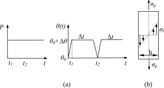
The problem to be considered is that of a cylindrical tube of mean radius R and wall thickness h that is closed at the ends [2]. The tube is subjected to an internal pressure p (Fig.1a) and a cyclic temperature gradient across its wall. The detailed temperature history of a cylindrical tube is given in Fig.1a, where θ(t) varies between θ0 and θ0+Δθ. The ambient temperature θ0 remains at 0C. The temperature distribution across the wall is assumed to be linear, during the first half of each cycle (the so-called start-up) and zero during the second half of each cycle (the so-called shut down). Bree [2] made the additional assumption that, since the hoop stress is the greater of the two stresses acting, the axial stress would be ignored. Thus the problem is reduced to that of a slab with a overall stress σp+σt acting in hoop direction only (Fig.1b), where the constant σpand cyclic σt is the hoop stress produced by the internal pressure and cyclic temperature distribution across the thickness, respectively.
The cylindrical tube is made of 304 stainless steel with the following material properties: yield stress σy=205
MPa, Poisson’s ratio, ѵ=0.3, Young’s modulus, E= 200 GPa, coefficient of thermal expansion, α=1.0x10⁻⁵. For
the creep material data in equation (9) we adopt B= 5.86e-15 and n=5.
3.2 Results and discussions
Fig.2 is the Bree [2] diagram, which illustrates the responses for the case of a pressurised cylinder subject to cyclic through-wall thermal stress. The ordinate and absicca give normalised values of pressure and thermal stress respectively, where the stresses have been normalised against the yield stress of the material. There are four main regions of interest. Region E is elastic, where pressure plus thermal stress is always less than the yield stress. Bree stated that creep ratcheting occurs if any combination of applied loading exceeds region E, with the assumption that the stress is fully relaxed [2]. Region S is shakedown. Region P is reversed plasticity, where yielding occurs on every cycle, but no incremental or ratcheting strain occurs. Region R indicates ratcheting, where finite strain growth occurs on every cycle.
enough to produce a full relaxation of creep stress . From Fig.3 it is observed that the calculated steady-state of stress and strain follows the path A1B1C1A2B2C2A3B3C3, etc. and reaches the point An at the end of the nth
start-up, the point Bn at the end of the nth dwell time and the point Cn at the end of the nth shutdown. Load case 2
(Fig.3a) exhibits a non creep ratcheting mechanism as the creep strain accumulation occurs only due to the primary stress, with no stress relaxation taking place. Load case 3 (Fig.3b), however, exhibits a creep ratcheting mechanism as an additional creep strain is accumulated due to stress relaxation in every cycle. Similar results are obtained from the analyses at load points 1 and 4 which confirm that the LMM can reproduce the analytical solutions of Bree [2].
Two cyclic load points 5 and 6, which are located in region S2 and P, respectively, are chosen for investigating the other cyclic response with creep effect beyond the creep ratcheting boundary. The steady state stress strain path for the cyclic loading points 5 and 6 with one hour and 50 hour dwell time period are shown in Fig.4 and Fig.5 respectively.
It is observed from Fig.4 that the steady-state stress and strain curve repeats the hysteresis loop ABC every subsequent cycle, reaching the point A at the end of each start-up, the point B at the end of each dwell time and the point C at the end of each shut down. Due to the relaxation process the component material yields during unloading. Thus, the phenomenon of a closed hysteresis loop is generated at the cyclic load point 5 (Fig.4a) and at the cyclic load point 6 (Fig.4b) with one hour dwell time. It is observed form Fig.4b that there is plasticity during both the loading and unloading process for cyclic load point 6. Additional reverse plastic strains, which recover the inelastic strain due to start-up and creep dwell processes, develop due to the interaction of plasticity and creep, thus enlarging the closed hysteresis loop.
Fig.5 shows that the steady state responses of the structure at load points 5 and 6 no longer form a closed cycle when the creep dwell time is increased from 1 hour to 50 hours. The non-closed cycle follows the path A1B1C1A2B2C2A3B3C3 showing a net accumulation of inelastic strain per cycle.
This phenomenon can be explained by the increase in dwell time causing a continuous increase in permanent creep strain. However, the reverse plastic strain, which can not increase unlimitedly due to the limited magnitude of residual stress, is not able to recover the creep strain (Fig.5a) or the combination of creep strain and plastic strain during start-up (Fig.5b). Therefore, an open hysteresis loop is formed when the dwell time is increased.
An important parameter that is used to assess the significance of creep behaviour is the elastic follow up factor, defined as
(18)
c c
E
Z
Where EEand E 3E/[2(1)] denotes the effective elastic modulus with uniaxial and multiaxial case,
respectively. cis the change in effective creep stress, and cis the effective creep strain during the dwell
period. Z=1 corresponds to relaxation with zero change in total strain, and Z=∞ corresponds to steady state creep with no stress relaxation. With the estimated elastic follow-up factor, the creep strain can be evaluated approximately using (18) if a stress change during the dwell period can be measured [12]. Table.1 shows the values of elastic follow up factor obtained from the loading cases of 5, 6 and 7 (Fig.2) at the location with the highest creep strain. It can be seen that the values are sensitive to loading type. For cyclic loading case 6, which has low levels of primary loading, the increase in dwell time causes small changes in Z because the majority of the creep strain comes from stress relaxation. An increase in dwell time at load point 7 however, with larger levels of primary loading, results in a dramatic increase in Z. Although stress relaxation occurs in this situation, the primary loading results in creep strains with little relaxation, which becomes dominant at large dwell times.
4 HOLED PLATE
4.1 Problem description
A more practical example, a plate with a central hole and subjected to varying thermal loads and constant mechanical load is analysed using the proposed new LMM.
The geometry of the structure and its finite element mesh are shown in Fig.6. The 20-node solid isoparametric element with reduced integration is adopted. The ratio between the diameter D of the hole and the length L of the plate is 0.2 and the ratio of the depth of the plate to the length L of the plate is 0.05. The plate is subjected to a temperature difference Δθ between the edge of the hole and the edge of the plate and uniaxial tension P acts along one side (Fig.6). The same material and creep properties are adopted as the Bree example in the previous section.
The detailed temperature history at the inner bore of the hole is given in Fig.7, where θ(t) varies between θ0 and θ0+Δθ. When the ambient temperature θ0 remains at 0C, the magnitudes of the maximum thermo elastic stresses for the above thermal loading extremes can be determined by the maximum temperature differenceΔθ
the reference temperature difference Δθ=Δθ0=500C determines the reference cyclic elastic thermal stress. Two thermal stress extremes with three load instances are adopted for this cyclic load history:
---Load instance (1): The temperature distribution and axial tension are applied.
---Load instance (2): Both loads are sustained during a creep dwell.
---Load instance (3): The temperature load is removed (thus indicating the end of creep dwell), and the constant axial tension remains applied.
4.2 Results and discussions
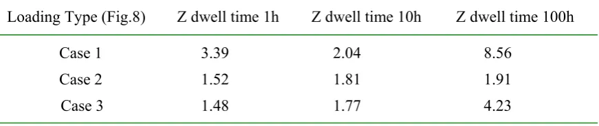
Fig.8 shows the shakedown and ratchet boundaries for the problem without the effects of creep, using the methods described in [8, 9]. In Fig.8 the applied uniaxial tension in the X-axis is normalized with respect to the reference uniaxial tension while the thermal load in the Y-axis is normalized by using the reference temperature differenceΔθ=Δθ0=500C. Three cyclic load cases 1 (Δθ=0.4Δθ0, σp=0.5σp0 ), 2 (Δθ=0.7Δθ0) and 3 (Δθ=0.7Δθ0,
σp=0.5σp0), which are located in the elastic shakedown and reverse plasticity region of the calculated boundary (Fig.8), are chosen to demonstrate the influence of different cyclic loading and dwell times on the cyclic response of a holed plate.
The locations of maximum creep strain correspond to different dwell period and cyclic load cases are shown in Fig.9 and Fig.10, respectively. It is observed from Figs.9-10 that the location of maximum creep stain changes with changing dwell period and types of cyclic load cases.
The locations of maximum plastic strain range correspond to different dwell period and cyclic load cases are shown in Fig.11 and Fig.12, respectively. It is observed from Figs.11-12 that the location of maximum plastic strain range changes with different types of cyclic load cases only, but it does not change with different dwell period.
4.2.1 Cyclic responses within elastic shakedown region: The stress strain response for load case 1
at location of maximum reverse plastic strain (Fig.11b) and maximum creep stain (Fig.9b) with dwell period of 10 hours is shown in Fig.13.
From Fig.13 it is observed that the calculated steady-state of stress and strain follows the path A1B1C1A2B2C2A3B3C3, etc. and reaches the point An at the end of the nth loading, the point Bn at the end of the
nth dwell time and the point Cn at the end of the nth unloading. Both locations exhibit creep ratcheting as
additional creep strain forms due to stress relaxation in every cycle.
value due to the formation of residual stresses in neighbouring regions. When considering possible failure mechanisms of the structure, both of these critical locations would need to be checked against different failure criteria (e.g. Location at Fig.11b for incremental plastic collapse and Location at Fig.9b for creep rupture).
4.2.2 The behaviour of cyclic response with changing dwell period: The steady state stress strain
paths for the cyclic loading case 3 (Fig.14) at the location of maximum reverse plastic strain with 1 and 10 hour dwell period are shown in Fig.14a and Fig.14b respectively. Fig.14a shows that the temperature gradient causes material to yield in compression on loading since the applied load is dominated by the compressive thermal stress. Then creep causes the inelastic strain increase in compression as the stresses relax. Removal of the temperature gradient causes the material to yield in tension during unloading and the reverse plastic strain recovers all the inelastic strain induced during loading and dwell time process. Therefore, the steady-state stress and strain curve (Fig.14a) repeats the hysteresis loop ABC with every subsequent cycle, reaching the point A at the end of each loading, the point B at the end of each dwell time and the point C at the end of each unloading. As the dwell period increases to 10 hours (Fig.14b), the stress relaxes further which causes the creep strain increase in compression. However, the small magnitude of creep stress causes a limited increase in creep strain. A larger reverse plastic strain is formed in tension during unloading due to the larger stress relaxation level. Thus, an opened hysteresis loop is generated and follows the stress strain path of A1B1C1A2B2C2A3B3C3.
4.2.3 The cyclic response with different applied loading: The steady state stress strain path for the
cyclic loading points 2 and 3 (Fig.8) at the location of maximum reverse plastic strain with 10 hours dwell period are shown in Fig.15a and Fig.15b respectively. It is observed from Fig.15a that the steady-state stress and strain curve forms a closed hysteresis loop (ABC) when only cyclic thermal loading is applied. With an additional constant mechanical load (Fig.15b) applied in the tensile direction the value of stress drop becomes larger, and thus enlarges the reverse plastic strain upon unloading. Therefore, an opened hysteresis loop is created and follows the stress strain path of A1B1C1A2B2C2A3B3C3.
The steady state stress strain paths for the cyclic loading points 1 and 3 (Fig.8) at the location of maximum reverse plastic strain with 10 hours dwell period are also compared in Fig. 16. It shows that with the increasing cyclic thermal loads (Fig. 16b), the higher temperature gradient causes material to yield in compression on loading. Larger creep strain is induced during stress relaxation process than that at load point 1 (Fig. 16a). Removal of this higher temperature gradient causes a larger reverse plastic strain compared with Fig.16a.
has primary loading involved, the increase in dwell time causes larger changes in Z comparing to the load case without primary load (load case 2). The reason is that with the increased dwell time for the case with primary load higher creep strain occurs due to the higher stress level than the load case which has no primary load. For cyclic loading case 1, smaller elastic follow-up factor with 10 hours dwell period is obtained comparing to the same case with 1 hour dwell period. This phenomenon can be explained by the change of the location of maximum creep strain due to the significant stress redistribution.
CONCLUSION
In the present study, the structural response under cyclic loading including the effect of creep has been investigated using the proposed new LMM and the following observations have arisen:
1. The new LMM has been derived and verified by the Bree problem, by being able to replicate the analytical creep ratchet limit. This method is able to evaluate the stable cyclic response (including creep and plastic strains) and elastic follow up factor. The new method has also been applied to a holed plate, and demonstrated its ability to determine the cyclic response and elastic follow up factor of more complex 3D structures.
2. Various cyclic responses for different loading conditions and dwell time periods have been investigated by the proposed method, which is able to address creep fatigue damage and creep ratcheting issues.
3. It is possible for a closed cycle to form when a creep dwell occurs during the cycle where the reverse plastic strains completely recover the inelastic strain created during loading and creep dwell. However, the cycle may become non-closed if the creep strains become too large for the reverse plastic strains to recover.
4. The open hysteresis loops are either caused by the accumulation of plastic strain (ratcheting) during each load cycle (Fig.13a and Fig.14b), or determined by the accumulation of creep strain due to the cyclically enhanced creep (Fig.3b) or steady state creep (Fig.3a).
ACKNOWLEDGEMENTS
The authors gratefully acknowledge the support of the Engineering and Physical Sciences Research Council (EP/G038880/1) of the United Kingdom, and the University of Strathclyde during the course of this work.
REFERENCES
2. Bree J., “Elastic-plastic behaviour of thin tubes subjected to internal pressure and intermittent high-heat fluxes with application to fast-nuclear-reactor fuel elements,” J. strain anal, 1967, 2, pp.226–238.
3. Bree J., “Incremental growth due to creep and plastic yielding of thin tubes subjected to internal pressure and cyclic thermal stresses,” J. strain anal, 1968, 3, pp.122–127.
4. ABAQUS. User’s manual. Version 6.7. 2007;
5. NguyenTajan, et al, “Determination of the stabilized response of a structure undergoing cyclic thermal-mechanical loads by a direct cyclic method”, ABAQUS Users' Conference Proceedings. 2003.
6. Ponter, A.R.S, & Chen, H.F., “A minimum theorem for cyclic load in excess of shakedown, with application to the evaluation of a ratchet limit.” European Journal of Mechanics - A/Solids. 2001; 20, pp.539-553.
7. Chen H.F., Ponter A.R.S., “A method for the evaluation of a ratchet limit and the amplitude of plastic strain for bodies subjected to cyclic loading.” European Journal of Mechanics- A/Solids. 2001; 20, pp. 555-571. 8. Chen, H.F., “Lower and Upper Bound Shakedown Analysis of structures With Temperature-Dependent Yield Stress.” Journal of Pressure Vessel Technology. 2010; 132, pp.1-8
9. Chen, H.F., “A Direct Method on the Evaluation of Ratchet Limit.” Journal of Pressure Vessel Technology. 2010; 132: 041202
10. Chen, H.F. & Ponter, A.R.S., “Linear Matching Method on the evaluation of plastic and creep behaviours for bodies subjected to cyclic thermal and mechanical loading.” International Journal for Numerical Methods in Engineering. 2006; 68, pp.13-32.
11. Tipping, D.J., “The Linear Matching Method: A Guide to the ABAQUS User Subroutines”, E/REP/BBGB/0017/ GEN/07, British Energy Generation. 2007.
Table Captions
Table 1 Values of the elastic follow-up factor Z at the location with the maximum creep strain
Table 1. Values of the elastic follow-up factor Z at the location with the maximum creep strain (Fig.2)
Loading Type (Fig.2) Z dwell time 1h Z dwell time 50h Z dwell time 100h
Case 5 Case 6 Case 7
1.59 1.24 3.32
2.73 1.84 11.55
3.19 1.94 20.96
Table 2. Values of the elastic follow-up factor Z at the location with the maximum creep strain (Fig.8)
Loading Type (Fig.8) Z dwell time 1h Z dwell time 10h Z dwell time 100h
Case 1 Case 2 Case 3
3.39 1.52 1.48
2.04 1.81 1.77
[image:16.595.81.517.352.444.2]Figure Captions
Fig.1 (a) Load history for constant internal pressure and cyclic temperature gradient (b) cross section in direction of applied stress
Fig.2 Bree diagram, showing regions of different cyclic behaviour. Axes show stress normalized by yield stress.
Fig. 3 Response of the stress-strain path corresponding to the cyclic loading cases (a) 2 (b) 3
Fig.4 Response of the stress-strain path corresponding to the cyclic loading cases with 1 hour dwell time (a) case 5 (b) case 6
Fig.5 Response of the stress-strain path corresponding to the cyclic loading cases with 50 hour dwell time (a) case 5 (b) case 6
Fig.6 (a) Geometry of the holed plate subjected to varying thermal loads and its finite element mesh (D/L=0.2) (b) FEM
Fig.7 Load history with two distinct extremes (three load instances) to the elastic solution.
Fig.8 Elastic shakedown, reverse plasticity and ratchet region for the holed plate with constant mechanical and varying thermal load
Fig.9 Location of maximum creep strain corresponding to the cyclic load case 1 with dwell period (a) 1 hour (b) 10 hour (c)100 hour
Fig.10 Location of maximum creep strain with 1 hour dwell period corresponding to the cyclic load (a) case 1 (b) case 2 (c) case 3
Fig.11 Location of maximum plastic strain range corresponding to the cyclic load case 1 with dwell period (a) 1 hour (b) 10 hour (c)100 hour
Fig.13 Response of the steady state stress-strain path corresponding to the cyclic load point 1(dwell period 10 hours) at the region with maximum (a) reverses plastic strain (b) creep strain
Fig.14 Response of the steady state stress-strain path corresponding to the cyclic load point 3 at the location with maximum reverse plastic strain with dwell period (a) one hour (b) 10 hour
Fig.15 Response of the steady state stress-strain path with dwell period 10 hours at the location with maximum reverse plastic strain corresponding to the cyclic load points (a) 2 (b) 3
(a) (b)
Fig. 1 (a) Load history for constant internal pressure and cyclic temperature gradient (b) cross section in direction of applied stress
P
t1 t2 t
θ0+∆θ
θ0
θ(t)
t1 t2 t
∆t ∆t σt
σp
[image:19.595.150.435.217.370.2]Fig.2 Bree diagram, showing regions of different cyclic behaviour. Axes show stress normalized by yield stress. 0.0
0.5 1.0 1.5 2.0 2.5 3.0 3.5 4.0 4.5
0 0.2 0.4 0.6 0.8 1 1.2
Bree boundary
Cyclic loading points
E
1
S
2
S
1
R
2
R
P
Load case 1
P
t
Load case 2 Load case 3 Load case 4
Load case 5 Load case 6
Load case 7
(a) (b)
Fig.3 Response of the stress-strain path corresponding to the cyclic loading cases (a) 2 (b) 3
-210 -150 -90 -30 30 90 150 210
A1B1
C1
A2
B2
C2
A3
B3
C3 Δεc=0.164%
-210 -150
-90 -30 30 90 150
210
A1
B1
C1
A2
B
C2
A3
B3
C3
Δεc=0.113
(a) (b)
Fig.4 Response of the stress-strain path corresponding to the cyclic loading cases with 1 hour dwell time (a) case 5 (b) case 6
-210 -150 -90 -30 30 90 150 210
-0.001 -0.0005 0 0.0005 0.001
A
B
C
Δεc=0.0289% Z=1.1
Δεp=0.0289
-210 -150 -90 -30 30 90 150 210
-0.0015 -0.001 -0.0005 0 0.0005 0.001 0.0015
A
B
C
Δεp=0.0238%
Δεc=0.0436%
Δεp=0.0674%
(a) (b)
Fig.5 Response of the stress-strain path corresponding to the cyclic loading cases with 50 hour dwell time (a) case 5 (b) case 6
-210 -150 -90 -30 30 90 150 210
A1
B1
C1
A2 A3
B2 B3
C2 C3
Δεc=0.0336% Z=2.7
Δεp=0.006%
-210 -150
-90 -30 30 90 150 210
A1B1
C1
A2
B2
C2
A3
B3
Δεp=0.0238%
Δεc=0.0855% Z=1.1
(a) (b)
Fig.7 Load history with two distinct extremes (three load instances) to the elastic solution. P
t1 t2 t
θ0+∆θ
θ0
θ(t)
t1 t2 t
Fig.8 Elastic shakedown, reverse plasticity and ratchet region for the holed plate with constant mechanical and varying thermal load
0.0 0.2 0.4 0.6 0.8 1.0 1.2 1.4 1.6 1.8 2.0
0.0 0.2 0.4 0.6 0.8 1.0 1.2 1.4 1.6 1.8 2.0
Shakedown and Ratchet boundary
Cyclic loading points
0
0
p p
Shakedown zone
Reverse plasticity zone Ratcheting zone
Load case 1
27
(a) (b) (c)
Fig.9 Location of maximum creep strain corresponding to the cyclic load case 1 with dwell period (a) 1 hour (b) 10 hour (c)100 hour
(a) (b) (c)
28
(a) (b) (c)
Fig.11 Location of maximum plastic strain range corresponding to the cyclic load case 1 with dwell period (a) 1 hour (b) 10 hour (c)100 hour
(a) (b) (c)
29
(a) (b)
Fig.13 Response of the steady state stress-strain path corresponding to the cyclic load point 1(dwell period 10 hours) at the region with maximum (a) reverses plastic strain (b) creep strain
-210 -150 -90 -30 30 90 150 210
A1 A2 A3
B1 B2 B3
C1 C2 C3
Δεc=0.00001%
Δεp=0.032%
-210 -150
-90 -30 30 90 150 210
A1 A2 A3
B1 B2 B3
C1 C2 C3
30
(a) (b)
Fig.14 Response of the steady state stress-strain path corresponding to the cyclic load point 3 at the location with maximum reverse plastic strain with dwell period (a) one hour (b) 10 hour
-210 -150
-90 -30 30 90 150 210
A1 A2 A3
B1 B2 B3
C1 C2 C3
Δεp=0.0106%
Δεp=0.153%
Δεc=0.052% Z=1.1
-210 -150 -90 -30 30 90 150 210
-0.0006 -0.0004 -0.0002 0 0.0002 0.0004
A B
C
Δεp=0.06%
Δεp=0.0107% Δεc=0.0493
31
(a) (b)
Fig.15 Response of the steady state stress-strain path with dwell period 10 hours at the location with maximum reverse plastic strain corresponding to the cyclic load points (a) 2 (b) 3
-210 -150 -90 -30 30 90 150 210
-0.001 -0.0008 -0.0006 -0.0004-0.0002 0 0.0002 0.0004
Δεp=0.098%
Δεc=0.087%
Z=1.47 Δε
p=0.011% A
B
C
-210 -150
-90 -30 30 90 150 210
A1 A2 A3
B1 B2 B3
C1 C2 C3
Δεp=0.0106%
Δεp=0.153%
Δεc=0.052%
32
(a) (b)
Fig.16 Response of the steady state stress-strain path with dwell period 10 hours at the location with maximum reverse plastic strain corresponding to the cyclic load points (a) 1 (b) 3
-210 -150 -90 -30 30 90 150 210
A1 A2 A3
B1 B2 B3
C1 C2 C3
Δεp=0.032%
Δεc=0.00001%
-210 -150
-90 -30 30 90 150 210
A1 A2 A3
B1 B2 B3
C1 C2 C3
Δεp=0.0106%
Δεp=0.153%