COMPARATIVE STUDY OF INTELLIGENT
CONTROLLERS FOR BRUSHLESS DC MOTOR
1P. SELVAKUMAR 2T.KANNADASAN
1Asst Prof,Department of EEE, SriGuru Institute of Technology, Coimbatore
2Assoc.Prof,Department of Chemical Engineering, Coimbatore Institute of Technology,
Coimbatore
Email:[email protected],[email protected]
ABSTRACT
In this paper, Brushless Direct Current Motor (BLDC) Drive using Matlab/Simulink is presented by developing an efficient Simulation model using Fuzzy Logic Controller (FLC).An efficient control of BLDC motor is controlled by FLC. A Comparative study of PID and FLC for speed and torque under various conditions were simulated and compared. The performance of the controllers is evaluated more precisely from various simulation studies for variations in the load torque and speed of BLDC motor drive. A performance comparison of two controllers is also carried out by taking various performance measures such as settling time, steady state error and peaks overshoot. The results confirm that the developed simulation model is very convenient for the precise evaluation of performance and the FLC shows improved performance over the PID controller in terms of disturbance rejection.
Keywords- BLDC Motor, Electric Drive Simulation, Fuzzy Logic, Matlab/Simulink
1.INTRODUCTION
BLDC motors have some advantages over conventional brushed DC motors and induction motors. Some of these are; better speed versus torque characteristics, high dynamic response, high efficiency, long operating life, noiseless operation and higher speed ranges. In addition, BLDC motors are reliable, easy to control, and inexpensive [1]. Due to their favorable electrical and mechanical properties, BLDC motors are widely used in servo applications such as automotive, aerospace, medical, instrumentation, actuation, robotics, machine tools, industrial automation equipment and so on recently [2-4].
Many machine design and control schemes have been developed to improve the performance of BLDC motor drives. The model of motor drives has to be known in order to implement an effective control in simulation. Some simulation models based on state-space equations, Fourier series, d-q axis model, and variable sampling have been proposed for the analysis of BLDC motor drives [5-10]. Furthermore, fuzzy logic controllers (FLCs) are used to analyze BLDC motor drives in literature [11-14]. The previous studies have made a great contribution to BLDC
motor drives. But as far as we know, a comprehensive approach has not been available
for modeling and analysis of fuzzy logic controlled brushless DC motor drives using MATLAB/Simulink.In this paper, a comprehensive simulation model with fuzzy logic controller is presented. MATLAB/fuzzy logic toolbox is used to design FLC, which is integrated into simulations with Simulink. The control algorithms, fuzzy logic and PID are compared. Several simulation results are shown to confirm the performance and the validity of the proposed model. The models based on system-level simulation make the simulation faster while it is able to provide greater details of the BLDC motor drive system. Besides, considering that the computational time without affecting the accuracy of the results obtained is very low, it can be said that the proposed method is promising.
2 MODELLING OF BLDC MOTOR.
accomplishes torque control of BLDC motor and the second loop is the BLDC motor
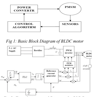
[image:2.595.94.279.162.357.2]Fig 1: Basic Block Diagram of BLDC motor
Fig 2: Fuzzy logic control Diagram for BLDC .
Fig.2 shows the overall block diagram of the developed model for BLDC motor drives. The analysis of BLDC motor is based on the following assumptions for simplification and accuracy. BLDC motor is not saturated. Stator resistances are equal, self and mutual inductances are constant. Semiconductor devices of inverter are ideal. Iron losses are negligible. Back-EMF wave forms of all phases are equal. Based on the equivalent circuit of BLDC motor and Inverter circuit with model of BLDC motor is shown in Figure 3, the dynamic equations of BLDC motors under the above assumptions are derived as:
= + (1)
Where Va, Vb and Vc are phase voltages, R is resistance, L is inductance, M is mutual inductance ea ,eb and ec are trapezoidal back EMFs. The motion equation is expressed as;
= )(Te-TL-Bωr) and =ωr (2)
where; Teis the electromagnetic torque, Tlis the load torque in Nm, J is the moment of inertia in kgm2, B is the frictional coefficient in Nms/rad, ωm is rotor speed in mechanical rad/s. and ωr is rotor speed in electrical rad/s.
Fig 3: Inverter Circuit with BLDC motormodel
3. INTRODUCTION TO FUZZY LOGIC
Fuzzy logic has rapidly become one of the most successful of today’s technology for developing sophisticated control system. With it aid complex requirement so may be implemented in amazingly simple, easily minted and inexpensive controllers. The past few years have witnessed a rapid growth in number and variety of application of fuzzy logic. The application range from consumer products such as cameras ,camcorder
,
washing machines and microwave ovens to industrial process control ,medical instrumentation ,and decision support system .many decision-making and problem solving tasks are too complex to be understand quantitatively however ,people succeed by using knowledge that is imprecise rather than precise . fuzzy logic is all about the relative importance of precision .fuzzy logic has two different meanings .in a narrow senses ,fuzzy logic is a logical system which is an extension of multi valued logic .but in wider sense fuzzy logic is synonymous with the theory of fuzzy sets . Fuzzy set theory is originally introduced by Lotfi Zadeh in the 1960,s[15] resembles approximate reasoning in it use of approximate information and uncertainty to generate decisions.Several studies show, both in simulations and experimental results, that Fuzzy Logic control yields superior results with respect to those obtained by conventional control algorithms thus, in industrial electronics the FLC control has become an attractive solution in controlling the electrical motor drives with large parameter variations like machine tools and robots. However, the FL Controllers design and tuning process is often complex because several quantities, such as membership functions, control rules, input and output gains, etc must be adjusted. The design process of a FLC can be simplified if some of the mentioned quantities are obtained from the parameters of a given Proportional-Integral controller (PIC) for the same application.
3.1. Structure Of FLC
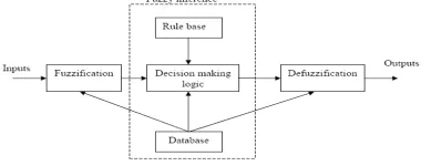
equations. Many systems are too complex to model accurately, even with complex mathematical equations; therefore traditional methods become infeasible in these systems. Figure 4. shows the structure of FLC However fuzzy logics linguistic terms provide a feasible method for defining the operational characteristics of such system.
Fig 4 : Structure of Fuzzy Logic
The fuzzy logic controller has three main components
1. Fuzzification 2. Fuzzy inference 3. Defuzzification
3.2. Design Of Fuzzy Control
The block diagram of FLC with two inputs 1 2 (e1,e2) and one output (u) is shown in Figure 9. The error is calculated by subtracting the reference speed from the actual rotor speed as follows:
e
1[n]=ω
ref[n]-ω
r[n] (3)
where e1[n] is the error, [ ] ω ref [n]is the reference speed, and ω r [n] is the actual motor speed. The change in error is calculated by Equation (16), where 1e [n −1] is the previous error value.
e
2[n]=e
1[n]-e
1[n-1] (4)
In the fuzzy logic control system, two normalization parameters (Ne1,Ne2) for input and one denormalization parameter (Nu) for output are defined. In normalization process, the input values are scaled between (-1, +1) and in the denormalization process, the output values of fuzzy controller are converted to a value depending on the terminal control element The fuzzy values obtained from fuzzy inference mechanism have to be converted to crisp output value (u) by defuzzifier process. For this purpose, the triangle fuzzy membership function is defined for each input and output values by seven clusters. Figure 5. Illustrates the
membership function used to fuzzify two input values (e1 ,e2 ) and defuziffy output (u) of the fuzzy controller. For seven clusters in the membership functions, seven linguistic variables are defined as: Negative Big (NB), Negative Medium (NM), Negative Small (NS), Zero (Z), Positive Small (PS), Positive Medium (PM), and Positive Big (PB).
Fig 5: Membership functions of fuzzy controller
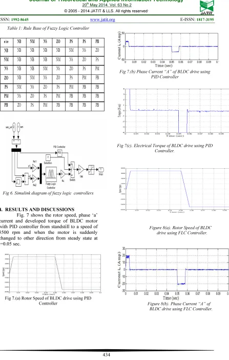
A sliding mode rule base used in FLC is given in Table 1. The fuzzy inference operation is implemented by using the 49 rules. The min-max compositional rule of inference and the center-of-gravity method have been used in defuzzifier process.
If e1 is NB and e2 is NB Then u is PB, If e1 is NB and e2 is NM Then u is PB, If e1 is NB and e2 is NS Then u is PM If e1 is NB and e2 is Z Then u is PM, and go on for all inputs.
Table 1: Rule Base of Fuzzy Logic Controller
Fig 6.Simulink diagram of fuzzy logic controllers
4. RESULTS AND DISCUSSIONS
Fig. 7 shows the rotor speed, phase ‘a’ current and developed torque of BLDC motor with PID controller from standstill to a speed of 3500 rpm and when the motor is suddenly changed to other direction from steady state at t=0.05 sec.
Fig 7.(a) Rotor Speed of BLDC drive using PID Controller
Fig 7.(b) Phase Current “A” of BLDC drive using PID Controller
Fig 7(c). Electrical Torque of BLDC drive using PID Controller.
Figure 8(a). Rotor Speed of BLDC drive using FLC Controller.
[image:4.595.89.296.140.444.2]Figure 8(c). Electrical Torque of BLDC drive using FLC Controller.
The fig. 8 shows the rotor speed, phase ‘a’ current and developed torque of BLDC motor with HFLC from Standstill to a speed of 3500 rpm and when the motor is suddenly changed to other direction from steady state at t=0.05 sec. PID controller and FLC have been employed for the speed control of BLDC motor. A performance comparison of PID controller and FLC has been carried out by several simulations. The results have shown that FLC is better than the PID controller for all the speeds.
5. CONCLUSION
In this paper, a comprehensive analysis of brushless DC drive system has been performed by using PID and fuzzy logic controller. The simulation model which is implemented in a modular manner under MATLAB/simulink environment allows that many dynamic characteristics such as phase currents, voltages, rotor speed, and mechanical torque can be effectively considered. Furthermore, the control algorithms, FLC and PID have been compared by using the developed model. It is seen that the desired real speed and torque values could be reached in a short time by FLC controller. The conclusion is that HFLC is found to be superior, more robust, faster and flexible and is insensitive to the parameter variations as compared with conventional PI and PID controllers.
REFERENCES
[1]. P. Yedamale, Brushless DC (BLDC) Motor
Fundamentals. Chandler, AZ:
MicrochipTechnology,Inc.,lastaccess;Marc h15,2009.[Online].Available:http://ww1.mi crochip.com/downloads/en/Market_Comm unication/Feb%202009%20microSOLUTI ONS.pdf
[2]. B.K. Lee and M. Ehsani, Advanced Simulation Model for Brushless DC Motor Drives, Electric Power Components and Systems 31, 841–868, 2003. M. Cunkas and O. Aydoğdu
229
[3]. W. Hong, W. Lee, and B.K. Lee, Dynamic Simulation of Brushless DC Motor Drives Considering Phase Commutation for Fuzzy Speed Control of Brushless DC Motor, ELECO’03, International
Conference on Automotive Applications,
Electric Machines & Drives Conference,
IEMDC '07, 2007.
[4]. R. Akkaya, A.A. Kulaksız, and O Aydogdu, DSP implementation of a PV system with GA-MLP-NN based MPPT controller supplying BLDC motor drive,
Energy Conv. and Management 48,
210-218, 2007.
[5]. P. Pillay and R. Krishnan, Modeling, simulation, and analysis of permanent-magnet motor drives, part II: the brushless DC motor drive, IEEE Trans. on Industry Applications 25, 274–279, 1989.
[6]. P.D. Evans and D. Brown, Simulation of brushless DC drives, Proc. of the IEE
137,299–308, 1990.
[7]. R. Carlson, M. Lajoie-Mazenc, and C.D.S. Fagundes, Analysis of torque ripple due to phase commutation in brushless DC machines, IEEE Trans. on Industry Applications 28, 632–638, 1992.
[8]. S.K. Safi, P.P. Acarnley, and A.G. Jack, Analysis and simulation of the high-speed torque performance of brushless DC motor drives, Proc. of the IEE 142, 191–200, 1995.
[9]. J. Figueroa, C. Brocart, J. Cros, and P. Viarouge, Simplified simulation methods for polyphase brushless DC motors,
Mathematics and Computers in Simulation
63, 209–224, 2003.
[10]. C.W. Hung; C.T. Lin, and C.W. Liu, An Efficient Simulation Technique for the Variable Sampling Effect of BLDC Motor Applications, IECON 2007, pp. 1175– 1179, 2007.
[11]. CK. Lee and WH. Pang, A Brushless DC Motor Speed Control System Using Fuzzy Rules, IEE Power Electronics and Variable Speed Drives, pp.101-106, 19Electrical
and Electronics Engineering, Bursa,
[12]. C. Xia, P. Guo, T. Shi, and M. Wang, Speed control of brushless dc motor using genetic algorithm based fuzzy controller,
Proc. of Int. Conf. on Intelligent
Mechatronics and Automation, pp.460-464,
2006.
[13]. A. Rubai, A. Ofoli, and M. Castro, dSPACE DSP-Based Rapid Prototyping of Fuzzy PID Controls for High Performance Brushless Servo Drives, IEEE Industry Applications Conference, 41st IAS Annual Meeting, page(s):1360–1364, 2006. [14]. B. Sing, A.H.N. Reddy, and S.S. Murthy,
Gain Scheduling Control of Permanent Magnet Brushless dc Motor, IE(I) Journal-EL 84, 52-62, 2003.
[15]. B.K. Lee and M.A. Ehsani, Simplified functional model for 3-phase voltage-source inverter using switching function concept, IEEE Trans. on Industrial Electronics 48, 309–321, 2001.