Theses Thesis/Dissertation Collections
8-2014
A Layer 2 Protocol to Protect the IP
Communication in a Wired Ethernet Network
Reiner Augusto Campillo TerreroFollow this and additional works at:http://scholarworks.rit.edu/theses
This Thesis is brought to you for free and open access by the Thesis/Dissertation Collections at RIT Scholar Works. It has been accepted for inclusion in Theses by an authorized administrator of RIT Scholar Works. For more information, please [email protected].
Recommended Citation
A Layer 2 Protocol to Protect the IP Communication in a
Wired Ethernet Network
By
Reiner Augusto Campillo Terrero
Thesis submitted in partial fulfillment of the requirements for the
degree of Master of Science in
Networking and System Administration
Rochester Institute of Technology
B. Thomas Golisano College
of
Computing and Information Sciences
Department of Information Sciences and Technologies
B. Thomas Golisano College
of
Computing and Information Sciences
Master of Science in Networking and System Administration
Thesis Approval Form
Student Name:
Reiner Augusto Campillo Terrero
Thesis Title:
A Layer 2 Protocol to Protect the IP Communication in a
Wired Ethernet Network
Thesis Committee
Name
Signature
Date
Tae Oh, Ph.D.
Chair
Sharon Mason, M.S.
Committee Member
i
ii
It is very gratifying when we can look at the results of the combined effort of many people and institutions that contributed to our success. I would like to express my gratitude to all those who directly and indirectly supported me during my days as grad student; my greatest appreciation to:
The government of The Dominican Republic, represented by the Ministry of
Higher Education, Science and Technology (MESCYT), for granting me the scholarship that allowed me to initiate and complete my master’s studies.
Rochester Institute of Technology for accepting me as a graduate student and for
the exceptional support and guidance they gave me. I would like to highlight the wonderful assistance given by Mrs. Diane Ellison.
Professor Dr. Tae Oh for being a great mentor to me, for trusting in my ideas and
for always encouraging me to continue with my research. As a thesis advisor, you always gave the extra mile. I’m also grateful to my committee members Professor Sharon Mason and Professor Bruce Hartpence; thank you for your accurate observations and input.
The College of Computing and Information Sciences for the exceptional advisory
given to me while I was enrolled as a grad student. I would like to particularly thank my academic advisor Mrs. Susan Herzberg. Regardless of how complicated a particular situation could be, your huge spirit and sweet understanding were always a fresh air that always put me on the right track.
The Dominican Advanced Network for Research and Education (RADEI) for
allowing me to use one of their servers and the virtual environment where we ran most of the tests shown in this thesis. Special thanks to Dr. Jose Pedro Diaz Gonzalez for his constant support and for his wonderful advices. Jose, I feel really lucky for having the support of such a veteran as you.
Dr. Felix Farias for reviewing the structure of my thesis and advising me in regards
iii
Linux Kernel, and the programming tools to manipulate Ethernet frames. You have always been a motive of inspiration for my researches in the IT field.
My roommates: Alberth, Marlenny, Evelyn and Raysa. There are not enough words
to describe the wonderful moments we spent together, supporting us each other to stay always on track. You were and still are part of my family. I also want to thank all new friends I made at RIT.
Mr. James Stefano for allowing me to work on campus as his assistant and for
always encouraging me to keep working hard. I will never forget the relaxing conversations we had at lunch break.
There are also those who have been with me during the good and bad days of my life, those who have always believed in me and have always encouraged me to move ahead and pursue my dreams:
Thank you God almighty, for giving me the wisdom, strength and perseverance to
achieve my goals.
To my wonderful parents Sheila and Cesar: You have been a great inspiration for
me to never give up, to go ahead and to fight for what I want. You taught me that we must always do things right, assume responsibility for our actions and always love what we do. I remember as a kid how you constantly confronted the most difficult of the situations to assure a better future for my sister and me, and how you sacrificed everything for us. I don’t have enough words to express my love and how thankful I’m to you. All I am now is because of your constant support, love and dedication to my sister and me. Thank you for being my parents.
To my great sister Yolena: Ever since we were kids, you never stopped surprising
iv
being separated for so long while I was doing my master’s studies was a remarkable demonstration of your love and understanding. I remember the
moments when I was explaining to you some of the images I present in this thesis, and how your input was a huge help for me to make them more understandable. I remember the moments of frustration during the testing phase when things got really complicated and how your voice and the soft touch of your hand kept me calmed. When the time came to defend this thesis in front of my committee
members, you were my inspiration to prepare my defense as a lawyer preparing and defending its case in court. You brought the necessary equilibrium to make this project a reality. Thank you for your love and support.
To my lovely grandmother Elena Galarza: Your example of honesty, commitment,
perseverance, love, bravery, discipline and hard work has stayed impregnated within all your family. Thank you for all your teachings and your eternal love.
To my great uncles, aunts and cousins: Thank you for your unconditional support
during all my life. Your actions are the true representation of love and family unity.
To my mother-in law, brothers-in law and sisters-in law: Thank you for believing
in me and for being my second family.
v
A Layer 2 Protocol to Protect the IP Communication in a Wired Ethernet Network
Reiner Augusto Campillo Terrero
Supervising Professor: Dr. Tae Oh
The IP protocol is the preferred data communication mechanism used nowadays. Data encapsulated using IP can be compromised if it is sent in clear text or without integrity protection, and even using known protocols to protect the confidentiality, integrity and authenticity of this data, the EtherType field of the Ethernet frames and the header of the IP packets in a wired Ethernet network still remain exposed opening possibilities for an attacker to gain knowledge of the network, cause a denial of service attack or steal information.
In this thesis, we propose a new protocol that protects the confidentiality, integrity and authenticity of the IP communication in a wired Ethernet network. This new protocol operates in the layer 2 of the OSI model, and for each Ethernet frame, it encapsulates the EtherType field and the entire IP packet into a new PDU structure that is partially
vi
DEDICATION ... i
ACKNOWLEDMENTS ... ii
ABSTRACT ... v
LIST OF TABLES ... viii
LIST OF FIGURES ... ix
1. INTRODUCTION ... 1
2. PROBLEM STATEMENT ... 4
3. RELATED WORK ... 6
4. PACKET SECURITY PROTOCOL ... 10
4.1. PDU Structure ... 12
4.2. Default Parameters ... 15
4.3. PSP Encapsulation Process in an Ethernet Environment ... 16
4.4. PSP Communication Process ... 19
4.4.1. Address Mapping ... 20
4.4.2. Communication Session Establishment ... 23
4.4.3. Session key Mapping ... 27
4.5. PSP Communication Process in an Ethernet Environment ... 28
4.5.1. Address Mapping ... 29
4.5.2. Session Communication Establishment and Session Key Mapping... 29
5. IMPLEMENTATION OF THE PROPOSED SOLUTION ... 32
5.1. Methodology and Scenario ... 32
5.2. Security Analysis ... 33
5.3. Performance Analysis ... 33
5.3.1. Tested Protocols and Services ... 34
5.3.2. Test Categories ... 34
5.4. Hardware and Software Specifications ... 36
vii
6. TEST RESULTS ... 43
6.1. Security Analysis ... 43
6.1.1. ARP Spoofing and Man in the Middle Attack ... 43
6.1.2. Vulnerabilities Derived From a Block Cipher in Electronic Codebook Mode ... 44
6.1.3. Conclusions of the Security Analysis ... 48
6.2. Performance Analysis ... 49
6.2.1. ARP-ICMP... 49
6.2.2. VoIP ... 51
6.2.3. Skype ... 54
6.2.4. IPERF-TCP ... 57
6.2.5. IPERF-UDP ... 67
6.2.6. SCP ... 71
6.2.7. Conclusions of the Performance Analysis ... 82
7. CONCLUSION ... 84
7.1. Future Work ... 85
viii
LIST OF TABLES
Table 4.1. Default Parameters of PSP……….. 15
Table 5.1. Protocols and Services Tested In Each Category……… 36
Table 6.1. Duplicate ACK Packets on Each Test Category for Iperf-TCP……..……… 62
ix
LIST OF FIGURES
Figure 4.1. Traditional Layer 2 vs. PSP Encapsulation……….….. 11
Figure 4.2. PSP Protocol Data Unit Structure………..……… 12
Figure 4.3. PSP Protocol Data Unit Structure Using Default Parameters……… 15
Figure 4.4. PSP Encapsulation Process in an Ethernet Environment………...……… 16
Figure 4.5. PSP Encryption Process……….……… 18
Figure 4.6. PSP Communication Process……….……… 19
Figure 4.7. PSP Communication Process – Step 1………...……… 20
Figure 4.8. Data Processed Through the OSI Model………...……… 21
Figure 4.9. ARP Request and Reply……… 22
Figure 4.10. PSP Communication Process – Step 2……….……… 23
Figure 4.11. PSP Communication Session Establishment Process……..……… 24
Figure 4.12. PSP Communication Session Establishment Process – PDU Structure…..………… 26
Figure 4.13. PSP Communication Process – Step 3……….……… 27
Figure 4.14. PSP Session Key Mapping………..……… 27
Figure 4.15. Data Processed Through the OSI Model with PSP Protection……… 28
Figure 4.16. ARP Over PSP……….……… 29
Figure 4.17. Complete PSP Communication Process in an Ethernet Environment…..……… 31
Figure 5.1. Network Topology……….……… 33
Figure 5.2. Network Topology for Skype Tests………...……… 34
Figure 5.3. Regular Data Transmission Process………..……… 39
Figure 5.4. Data Transmission Process Using PSP………..……… 40
Figure 5.5. Block Diagram of the PSP’s Developed Program……….……… 40
Figure 5.6. Block Diagram of the PSP’s Developed Program without the Encryption, Decryption and HMAC Modules………..……… 42
Figure 6.1. User Credentials Captured in our SSH Honeypot……….… 44
Figure 6.2. Data Captured by Attacker Vs. Data Captured by Analyzer……….………… 45
Figure 6.3. Structure of a Data Frame with Packet Security Protocol……….………… 45
Figure 6.4. Data Encrypted Using a Block Cipher in Electronic Codebook Mode……….……… 46
Figure 6.5. Data Encrypted Using a Block Cipher in Cipher-Block Chaining Mode (CBC)..…… 47
x
Figure 6.7. SIPp Performance………..……… 51
Figure 6.8. Average Calculated Jitter Per Call…….……… 52
Figure 6.9. CPU Usage of Asterisk and PSP……… 52
Figure 6.10. Asterisk Memory Usage………..……… 53
Figure 6.11. PSP Memory Usage During the VoIP Test………….……… 53
Figure 6.12. VoIP Transfer Rate in Bytes/Second………...……… 54
Figure 6.13. Skype Network Performance………...……… 55
Figure 6.14. CPU Usage of Skype, PSP and PSP in the Router………..……… 55
Figure 6.15. Skype Memory Usage………..……… 56
Figure 6.16. PSP Memory Usage in the Host and in the Router During the SkypeTest………..… 56
Figure 6.17. Skype Transfer Rate in Bytes/Second……….……… 57
Figure 6.18. Iperf TCP Performance……… 58
Figure 6.19. CPU Usage of Iperf-TCP and PSP………..……… 59
Figure 6.20. Iperf-TCP Memory Usage………...……… 59
Figure 6.21. PSP Memory Usage During the Ipert-TCP Test………..……… 60
Figure 6.22. Iperf-TCP Transfer Rate in Bytes/Second………...……… 60
Figure 6.23. Iperf-TCP Round Trip Time……… 61
Figure 6.24. Iperf-TCP Time/Sequence………...……… 63
Figure 6.25. Iperf-TCP Throughput……….……… 64
Figure 6.26. Iperf-TCP Window Scaling – Server Side…………...……… 65
Figure 6.27. Iperf-TCP Window Scaling – Server Side vs. RTT of Test Category 4-PSP-FULL.. 66
Figure 6.28. Iperf UDP Performance………...………… 67
Figure 6.29. CPU Usage of Iperf-UDP and PSP………..……… 68
Figure 6.30. Ipetf-UDP Memory Usage………...……… 68
Figure 6.31. PSP Memory Usage During the Ipert-UDP Test……….……… 69
Figure 6.32. UDP Lost Datagrams………...……… 69
Figure 6.33. Jitter in the Iperf-UDP Test……….……… 70
Figure 6.34. Iperf-UDP Transfer Rate in Bytes/Second…………..……… 70
Figure 6.35. SCP Network Performance………..……… 71
Figure 6.36. PSP, SSH and SCP CPU Usage………...……… 72
Figure 6.37. SSH Memory Usage……… 73
Figure 6.38. SCP Memory Usage……….………… 73
Figure 6.39. PSP Memory Usage During the SCP Test………...…… 74
xi
Figure 6.41. SCP Round Trip Time……….……… 75 Figure 6.42. SCP Time/Sequence……… 77 Figure 6.43. SCP Time/Sequence Graph in Test Category 4-PSP-FULL with no Reverse DNS
1
1. INTRODUCTION
The IP protocol is one of the key elements that make communication possible in today’s data networks; its main purpose is to provide an addressing mechanism for the delivery of data between two hosts regardless of their physical location [1]. Data communicated using this protocol is encapsulated into IP packets [2] that, in their basic structure, are sent over the network in clear text allowing any eavesdropper to read the entire content of what has been transmitted; moreover, the IP communication was designed without taking into consideration any need of confidentiality [3], and by default, all data transmission between two hosts can be compromised.
Known protocols, as for example TLS, SSH and IPSec, have been developed to protect the confidentiality and integrity of the information transmitted over IP [4], but fail to offer this protection to the header of the IP packets leaving it exposed in clear text and opening possibilities for an attacker to gain knowledge of the network, disrupt the communication or steal information. In the case of wireless Ethernet networks, this problem has been thoroughly approached, and protocols such as WPA and WPA2 were developed as a solution to protect the confidentiality and integrity of the entire IP packets, including the IP header and the transmitted data [5]; however, the problem is still present in wired Ethernet networks. In order to protect the entire IP communication in these networks, it is necessary to increase security at the OSI’s layer 2 level by offering confidentiality protection to the EtherType field of the Ethernet frame and the encapsulated IP packet, and integrity protection to the entire Ethernet frame.
2
proposed a solution with the standard IEEE 802.1AE called MACSEC [8] and provides confidentiality, integrity and authenticity protection at the layer 2 level; however, its implementation can represent a huge investment in new hardware, limiting the scenarios where it can be implemented. Another solution was proposed by Yves Igor Jerschow, Christian Lochert, Bjorn Scheuermann and Martin Mauve [9] with a protocol called Cryptographic Link Layer (CLL) which provides authentication, integrity, confidentiality and replay attack protection to the IP packets in the link layer; however, this protocol strongly relies on digital certificates to authenticate hosts. In addition, encryption of data is optional and doesn’t include ARP, broadcast or DHCP packets.
In this thesis, we propose a new layer 2 protocol called Packet Security Protocol (PSP) to protect the confidentiality, integrity and authenticity of the IP communication in a wired Ethernet network. Our proposed solution is designed for flexibility, allowing the use of multiple encryption and hashing algorithms as well as multiple digital certificate standards. When protecting data with PSP, the ethertype field of the Ethernet frame is replaced with a new value that indicates the PSP protocol; the protected data is then encapsulated into a new PDU structure that includes the original ethertype field of the Ethernet frame and the entire IP packet, both encrypted with a symmetric key, and an integrity check value that can be either an HMAC value or a digital signature calculated over the entire Ethernet frame. Our proposed protocol also includes multiple options to protect the communication against reply attacks.
To demonstrate the proof of concept of our solution, we will develop a program in C++ that implements the new protocol in a Linux operating system. This demonstration will be based on a methodology consisting of two parts. First, we will analyze the security of our proposed protocol by performing different attacks to compromise the communication between two hosts, and later, we will protect the same communication with our solution; we will also analyze the impact on security caused by the use of different modes of operation of a block cipher. Second, we will run multiple tests to 7 different protocols to measure the performance of the network and the performance of the hosts using our proposed solution.
3
1. What are the real consequences of leaving the IP header unprotected in a wired
Ethernet Network?
2. When encrypting information, what is the impact caused by different modes of
operation of a block cipher in terms of security?
3. Is the network and host performance highly impacted when protecting the
confidentiality and integrity of the entire IP packet?
4. Is it convenient for any kind of scenario to offer such level of protection?
The main contribution of this thesis is to present a new protocol that protects the confidentiality, integrity and authenticity of the entire IP packets in a wired Ethernet network and is also flexible to be used by any host, under any networking scenario.
The rest of this work is presented in the following order: Chapter 2 thoroughly
4
2. PROBLEM STATEMENT
Several mechanisms and protocols have been developed to protect the confidentiality and integrity of the IP communication. An example of these protocols is IPsec, a suit of protocols that provides mechanisms to protect the confidentiality, integrity and authenticity of the payload of an IP packet. It also can, in its tunnel mode, encapsulate the entire IP packet (header + payload), add a new unencrypted IP header, and prevent the original header information from being exposed [10].
In a wireless Ethernet network, the header and payload of an IP packet is encrypted and integrity protected at the OSI’s layer 2 level using protocols such as WPA and WPA2 [5] preventing unauthorized users from understanding the frames traveling across the network. This scenario is different in a wired Ethernet network because existing security protocols, as for example IPsec, SSH or TLS, can protect the transmitted data; however, this
protection occurs in the network and upper layers of the OSI model [4], leaving the EtherType field of the Ethernet frames and the header of the IP packets exposed in clear text absent from any confidentiality and integrity protection. To better understand this problem, it is necessary to talk about layered models.
5
6
3. RELATED WORK
Research and development of protocols and technics to protect, in the layer 2 of the OSI model, the confidentiality or integrity of the information transmitted over a wired network expands to several solutions that, to our understanding, don’t offer a complete protection to the information.
The Point to Point Protocol (PPP) is a well-known solution used to transmit other protocol’s packets in a point to point link. Several methods have been defined to increase the functions of this protocol, including the ability to encrypt the entire encapsulated packet as specified in the PPP Encryption Control Protocol (ECP) [6]. This protocol defines a standard method to encrypt information in a PPP link and is open to any encryption algorithm, but it doesn’t specify any method to protect the integrity or
authenticity of the information being transmitted, providing only confidentiality protection [6]. Another disadvantage of the ECP protocol is that it can be used just after the Link Establishment Phase and the Authentication Phase of the PPP protocol, and not before. It means that an attacker can sniff the entire Link establishment phase of PPP in clear text and send multiple attacks to avoid a successful link negotiation.
Any protection to the information transmitted in a PPP link must be done through additional protocols. Confidentiality protection is achieved through ECP, but
authentication protection must be done through different authentication protocols that can send the information in clear text or as a cryptographic hash. The big flaw of PPP and ECP is that there isn’t a defined protocol to protect the integrity of the information [6][14]. It means that an attacker can manipulate and modify the data and the receiving end won’t realize that it was modified.
7
algorithm is vulnerable to key attacks and an attacker can retrieve the key, just as demonstrated by Fluhrer, Mantin and Shamir [16].
Dr. Kwei Tu [7] proposed a protocol to provide authentication, integrity,
confidentiality and replay attack protection at the link layer level to the communication between two nodes. This protocol uses a shared secret data and time codes between the communicating devices. It also uses HMAC-SHA-2 as the only algorithm for data authentication, integrity and session key generation; and AES as the only data encryption protocol. Dr. Tu explains the implementation of this protocol on a CCSDS (Consultative Committee on Space Data Systems) Data format but does not specify if it could be used to protect Ethernet, PPP or any other layer 2 protocol. Dr. Tu’s solution is limited to only one encryption and hashing algorithm. His protocol is limited to the vulnerabilities found on the only algorithm it uses. It also uses time codes for the communication which could be either convenient or not depending on the scenario where it is implemented.
The IEEE developed the IEEE 802.1AE standard known as the media access control security (MacSec) standard for local and metropolitan area networks. It provides
confidentiality and integrity protection to trusted network hosts. MacSec uses the terms Mac Security Entity (SecY) to define the host or network element that uses MacSec, and Secure Association Key (SAK) to define the secret key used between two hosts that have established a Secure Association [8]. Even though MacSec defines encryption and integrity protection, it has to rely on the standard IEEE 802.1X-2010 for authentication and key management [17].
MacSec combined with IEEE 802.1X-2010 offers a good protection to the layer 2 frames; however, it must be supported by the physical hardware of the network including network switches. This condition may force to make investment in new hardware, limiting the number of scenarios where it can be adopted.
Yves Igor Jerschow, Christian Lochert, Bjorn Scheuermann and Martin Mauve [9] proposed a protocol called Cryptographic Link Layer (CLL) which provides
8
values to authenticate the frames transmitted by a host. In the case of digital certificate, it binds the Mac and IP address of the host and the receiver can always validate the
authenticity of the frame based on these parameters.
CLL encapsulates the IP packet and adds a new header and a HMAC value or digital signature to the protected frame. It works in the following way: When a host needs to communicate with another host, it must use the ARP protocol to map the MAC and IP address. These ARP packets have a nonce and a timestamp and are authenticated using a digital certificate issued by a certificate authority. The next step is to establish a security association between both hosts. In this stage, hosts negotiate different security parameters and a common symmetric key to calculate the HMAC of the frames and use this value to authenticate and protect the integrity of the frames instead of using digital certificates. Hosts can optionally decide to encrypt the IP packet as well.
We consider CLL to have the closest approach to a complete and efficient protection of the IP packet at the data link layer level in a wired Ethernet network; however, it has certain limitations that can result in an administrative burden to the network administrator. It also has other disadvantages that can allow an attacker to gain knowledge of the
network, especially all information contained in the IP headers of the packets, and find new ways to disrupt the communication and compromise the data.
CLL uses timestamps to protect the ARP and security association packets from reply attacks. It also relies exclusively on digital certificates to authenticate ARP, DHCP and broadcast packets and doesn’t include another way to authenticate these. CLL is not open to disable timestamps or digital certificates, which requires the network to have a
certificate authority and a way to keep all hosts with their clocks synchronized. These two requirements, depending on the scenario, can significantly increase the administrative tasks of the network.
9
10
4. PACKET SECURITY PROTOCOL
In this thesis, we propose the creation of a new data link protocol that will provide a secure transmission preserving the confidentiality, integrity and authenticity of the information sent over a wired Ethernet network. From this point on, we will refer to our proposed protocol as Packet Security Protocol or PSP.
We designed PSP considering the following characteristics:
It must provide a mechanism to protect the confidentiality, integrity and
authenticity of the information being transmitted.
It must protect the communication from replay attacks.
It must act as a security layer regardless of the network protocol being used.
It must encrypt the information contained in all fields of the header of the used
communication protocol.
It must not send relevant information in clear text at any time.
It must support multiple hashing and encryption algorithms.
It must support multiple digital certificate standards.
It must be completely open to allow a network administrator to choose the security
parameters used to protect the communication.
It must be compatible with existing network equipments.
The ethertype field of an Ethernet frame and the header of the IP communication protocol in its versions IPv4 and IPv6 are transmitted in clear text even if the entire IP packet is encrypted and tunneled by any known network security protocol. This lack of protection makes the transmitted information more vulnerable to any kind of attack.
11
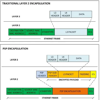
Figure 4.1. Traditional Layer 2 vs. PSP Encapsulation
A general overview of the traditional layer 2 encapsulation vs. the PSP encapsulation is depicted in Figure 4.1. Taking the OSI model as a reference in a regular data network communication, layer 3 packets are encapsulated into a layer 2 frame and then transmitted over a physical medium. PSP respects and works together with the traditional
12
4.1. PDU Structure
The PSP Protocol Data Unit (PDU) is composed of 3 sections: clear text header, encrypted payload and integrity check value.
Figure 4.2. PSP Protocol Data Unit Structure
Each section of the Packet Security Protocol PDU structure, along with the fields they contain, is shown in Figure 4.2.
The clear text header has information about the PSP version and the different security parameters used to protect the data. It contains 3 mandatory fields and 2 others that are optional:
Version (3 bits): It Indicates the PSP version. The Packet Security Protocol proposed in this thesis is version 0.
Security Flags (5 bits): This field contains 4 bits that indicate the reply attack protection mechanism, confidentiality and integrity protection of the encapsulated data. There is a fifth bit that is reserved for future purposes.
o Security Number Flag: If set to 1, a security number will be used as reply
attack protection mechanism combined with a sequence number. This is an optional feature and is set to 0 by default.
o Time Stamp Flag: If set to 1, a time stamp will be used as reply attack
13
combined with a security number. This is an optional feature and is set to 0 by default.
o Reserved Flag: This bit is reserved for future security purposes.
o Digital Signature Flag: This flag is used to indicate if either an HMAC or Digital signature is used to preserve the authenticity and integrity of the protected data. 0 indicates HMAC and 1 indicates Digital Signature.
o Encryption Flag: This flag indicates if the protected data will be either
encrypted or not. By default, this flag is set to 1 (encryption on).
Sequence Number (32 bits): It is a number used to keep track of the order of the frames. It also works as a protection against replay attacks. This number is increased every time a frame is sent.
If a frame is received with a sequence number lower or equal to the sequence number of the last received frame, it is automatically discarded. The sequence number of the first transmitted frame always starts with a random value.
Security Number (Optional. 24 bits): This is an optional replay attack protection mechanism consisting of a random generated number that changes every certain time. All hosts must be synchronized with the same number and change it at the same time. When used, the security number flag is set to one. If a frame is received with a security number different than the value generated by the receiving host, the frame is automatically discarded.
For this number to be used there has to be a method to effectively install it on the host. It can be done manually or through a server.
Time Stamp (Optional. 32 bits): This is an optional replay attack protection mechanism that indicates the exact time at which a frame was transmitted. All hosts must be synchronized with the same time. When used, the time stamp flag is set to one. If a frame is received with a time stamp different than the current time of the receiving host, the frame is automatically discarded.
14
cryptographic key using an encryption algorithm and can only be extracted or analyzed once the section has been decrypted.
Protocol Type (16 bits): This field indicates the protocol that is being protected. When constructing the PSP PDU, the Ether Type field of the layer 2 frame is replaced with 0x1982 to indicate PSP as the encapsulated protocol. The replaced ether type value is then added to the Protocol Type field of the PSP PDU. This field can also indicate a sub protocol of PSP, like the Session Establishment Protocol. Padding Size (8 bits): It indicates the size of the Padding field in bytes.
Data (Variable): This field contains the data (header and payload of an IP packet or any other protocol) to be protected. Depending on the security flags, encryption algorithm and integrity protection used, this field can be of up to 11,808 bits (1,476 bytes).
Padding (Up to 512 bits): This field contains the padding bytes necessary to complete the size of a full block when a block cipher algorithm is used for
encryption. The padding bytes can be all 0x00, 0xFF or any defined value. The size of this field can be of up to 512 bits (64 bytes).
The integrity check value (ICV) section guarantees the integrity and authenticity of the frame. This section contains either an HMAC value or a Digital Signature calculated for the entire layer 2 frame, but not both.
HMAC (Up to 1024 bits): If the Digital Signature Flag is set to 0, an HMAC is calculated for the entire layer 2 frame. This kind of ICV can be used for any kind of data to be protected, including unicast, broadcast and multicast packets.
Digital Signature (Up to 8,192 bits): If the Digital Signature Flag is set to 1, the entire layer 2 frame will be digitally signed using a private key. This kind of ICV is to be used exclusively for broadcast and multicast messages, and for unicast
packets between hosts that haven’t yet established a communication session.
15
4.2. Default Parameters
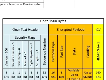
[image:29.612.151.489.363.619.2]By default, PSP uses only the sequence number as reply attack protection. It also encrypts the data with a shared symmetric key using the Blowfish encryption algorithm in Cipher Block Chaining mode, and calculates an HMAC value using the SHA-1 hashing algorithm to protect the integrity and authenticity of the frame. PSP encrypts the data and calculates the HMAC values with the same symmetric key. All default parameters of PSP are shown in Table 4.1.
Table 4.1. Default Parameters of PSP
Clear Text Header Encrypted Payload Integrity Check Value Version = 0
Blowfish-CBC as encryption algorithm.
HMAC-SHA1 as hashing algorithm.
Security Number Flag = 0 Time Stamp Flag = 0 Reserved Flag = 0 Digital Signature Flag = 0 Encryption Flag = 1
Sequence Number = Random value
Figure 4.3. PSP Protocol Data Unit Structure Using Default Parameters
16
Number, and it always starts at a random value. The next bytes correspond to the
Encrypted Payload and there is not a fixed length for this section. The last 20 bytes (160 bits) correspond to the calculated HMAC-SHA1 value.
Even though, PSP uses Blowfish-CBC and HMAC-SHA1 as default encryption and hashing algorithms, it has been designed to support other algorithms as well as multiple digital certificate standards. Section 4.4.2 explains how two hosts establish a
communication session and how they negotiate the encryption and hashing algorithms used to protect that session.
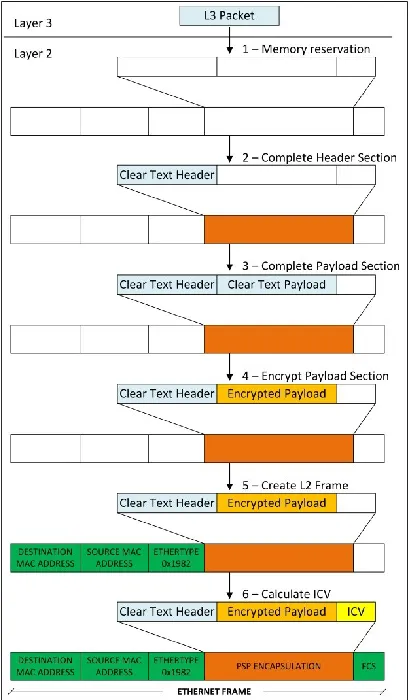
[image:30.612.218.423.290.640.2]4.3. PSP Encapsulation Process in an Ethernet Environment
Figure 4.4. PSP Encapsulation Process in an Ethernet Environment
17
is sent to layer 2, the first step PSP takes in the encapsulation process is to reserve buffer memory to create the layer 2 frame. At this point, memory is reserved for each one of the fields of the frame, including the PSP PDU structure based on the security parameters used to protect the data.
Once memory has been reserved, the second step is to complete the PSP header with all necessary information. The PSP version, Security flags and the Sequence Number fields are added. If the Security Number and Time Stamp are necessary, these two fields are added as well.
After completing the PSP header, the third step is to complete the Payload section adding the layer 3 protocol into the Protocol Type, Pad size, Layer 3 packet fields and the padding bytes necessary to complete a block size in case a block cipher is used. Something very important to consider about this step is that the section is still in clear text, no data has been encrypted yet.
The fourth step is to encrypt the payload section using a defined encryption algorithm. In the case of algorithms that require an initialization vector (IV), PSP uses a unique IV/cryptographic key pair every time it encrypts the data to avoid the formation of patterns of blocks that have the same clear text. Every time a new symmetric cryptographic key is defined, PSP calculates the HMAC-SHA1 of this new key and uses the resulting value as a Base IV Number to calculate the initialization vector (IV), which is defined by a
mathematical function of the Base IV Number (BIVN) and the Sequence Number (SN):
IV = f(BIVN, SN)
With this approach, an attacker would never know the real IV used to encrypt the data.
By default, PSP uses addition as the mathematical function to calculate the IV:
18
Figure 4.5. PSP Encryption Process
Once the Initialization Vector has been calculated, as depicted in Figure 4.5, it is passed to the encryption algorithm to encrypt the payload section.
The fifth step in the encapsulation process is the formation of the layer 2 frame. PSP adds the Destination and Source Mac Address, the Ethertype field, and the Encrypted Payload section. We have established 0x1982 as the value of the Ethertype field to identify PSP as the encapsulated protocol.
19
4.4. PSP Communication Process
PSP works at the layer 2 of the OSI model. It must be configured, along with a common default Pre-Shared Symmetric Key, on all devices that will talk directly to each other in a communication network. All communication between two devices configured with PSP is encrypted and authenticated.
PSP uses a process of three sequential steps that will allow two devices to
communicate with each other: Address Mapping, Communication Session Establishment, and Session Key Mapping.
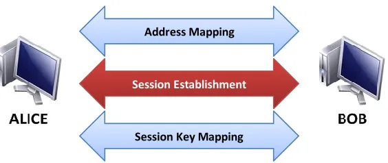
Figure 4.6. PSP Communication Process
As depicted in Figure 4.6, the first process is to map the network address of the peer host with its hardware address. Once the address mapping is done, PSP uses a Session Establishment Protocol to establish a communication session and be able to exchange data with the peer host; during this process, a session key is created to encrypt the
communication and avoid using the default Pre-Shared Symmetric Key. After the communication session has been established, both hosts do a Session Key to Hardware Address Mapping. With this process, by creating an association between a session key and the hardware address of the peer, a device can know what session key to use to decrypt or encrypt data. This last process is necessary when a device has established communication sessions with more than one device.
Each process is explained in more details below. Address Mapping
Session Establishment
20
4.4.1. Address Mapping
Figure 4.7. PSP Communication Process – Step 1
All network devices have two types of addresses: Hardware address, and Logical or Network address. Routing of packets in a communication network as we know it today, is possible because of the Logical or Network address of the devices involved. A Network Address indicates the location of a device and also, because of its logical characteristic and protocols associated, multiple routes or paths can be used to reach it [18]. When we talk about a Network address, we can think about a device location, network and route or path.
A Hardware address is the unique identifier of the network interface module of a device. This address is not used for routing of information, but to identify the device in a physical network. It means that, all devices connected to the same physical local network, can send frames to each other using their hardware address [18]. In other words, we can say that a hardware address is the address used by a device to send a frame to another device or devices that are in the same physical local network.
Regardless of the Network address and the protocols being used in the upper layers of the OSI model, the Hardware address is always necessary to reach a device in the same physical local network.
All data communication needs to map network and hardware addresses. To better understand this process; let’s review the OSI model and the ARP protocol.
4.4.1.1. OSI Model and Address Resolution Protocol
Before explaining PSP Network to Hardware Address Mapping in more details, it is necessary to have a good understanding of how the Data is processed through the OSI
Address Mapping
Mapping
Session Establishment
21
[image:35.612.103.539.168.360.2]model since its generation to its delivery. It is also necessary to understand how address mapping protocols work. For this purpose, we will explain the Address Resolution Protocol. If you already understand how the OSI model and the Address Resolution Protocol work, you can skip this section.
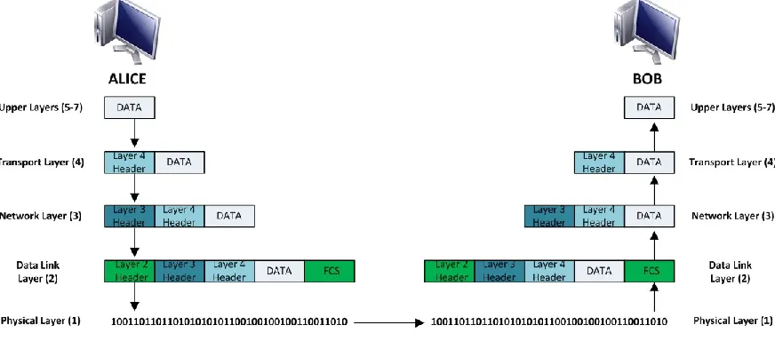
Figure 4.8. Data Processed Through the OSI Model
In the scenario shown in Figure 4.8, Alice wants to send a unicast packet to Bob – a unicast is a packet sent to one destination [19]-. This data, which is generated in the upper layers of the OSI model, is encapsulated in a transport layer that will append a header indicating the source and destination port, the transport protocol and some other
parameters that are not relevant for the purpose of this explanation. This new segment is passed to the network layer and a new header is appended indicating the version of the IP protocol, the source and destination IP addresses, and some other parameters. This packet is passed to the Data link layer, which appends another header indicating the source and destination MAC addresses, and other parameters. Finally, the data is sent over to Bob as bits traveling through the media used to connect the equipment to the network (Cable, Air, Fiber, etc.) [20].
22
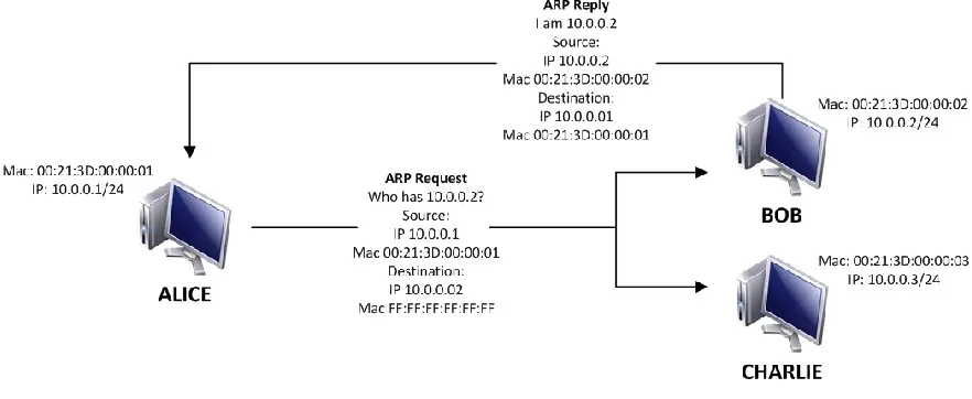
Figure 4.9. ARP Request and Reply
Alice and Bob can communicate because both hosts know the Mac and IP addresses of each other (Hardware and Network addresses). If this information is missing, it is
necessary to use the Address Resolution Protocol to map both addresses [21]. In the previous example of Alice sending a unicast packet to Bob, if Alice doesn’t know the Mac address, she won’t know how to structure the layer 2 header. What Alice will do, as depicted in Figure 4.9, is to send a layer 2 broadcast asking “What is the Mac address of Bob” – a broadcast is a packet sent to all possible destinations at the same time [19]-. All hosts connected to the same Hub or Switch will receive the broadcast but only Bob, if he is in the same layer 3 subnet as Alice, will reply with his own Mac address”.
4.4.1.2. PSP Address Mapping Explained
Now that we understand how Data is processed through the OSI model and how an address mapping protocol works, we can explain how address mapping occurs in PSP.
PSP creates an address mapping table from any PSP packet that enters the interface where the protocol is configured. The packet must belong to the same subnet.
There are multiple ways to get the source hardware and network addresses:
We can get the source hardware and network addresses by using the ARP or NDP
protocols, depending if the protected protocol is either IPv4 or IPv6.
Manually created ARP or NDP tables.
23
When a PSP packet is received, if there is not a communication session established, the device tries to decrypt it using the installed common pre-shared symmetric key. If
successful, it will look into the source and destination address fields of the network protocol that is being protected. If the network address is in the same subnet, and if the destination address is the receiver’s address, a multicast or broadcast address; it will be mapped with the source hardware address specified in the layer 2 header. If a device is able to decrypt a PSP packet, and it is not using digital certificate protection to authenticate the sender, it will be assumed that it was sent by a trusted source.
4.4.2. Communication Session Establishment
[image:37.612.181.463.274.393.2]
Figure 4.10. PSP Communication Process – Step 2
The second step in the PSP communication process is the establishment of a
communication session that is unique to the hosts trying to communicate with each other. This step is handled by the PSP Session Establishment Protocol (PSP SEP) and occurs only if two conditions are met: 1) the initiator has mapped the network and hardware addresses of the receiver. 2) The sender wants to send a packet to the receiver.
The PSP Session Establishment Protocol (PSP SEP) is responsible for establishing a communication session between two hosts that wants to communicate with each other. The protocol negotiates the security parameters of the communication session including
encryption and hashing algorithms, unique session symmetric key, Base Initialization Vector Number (BIVN), mathematical function to calculate the IV, communication session expiration time, communication session reestablishment and communication session finalization.
Address Mapping
Mapping Session Establishment
24
PSP SEP consists of 3 stages to establish a communication session: Session Establishment Request, Hash and Encryption Negotiation, and Session Parameters Negotiation.
We will retake the names “Alice” and “Bob” to represent the devices involved in a PSP communication and make this explanation more understandable.
[image:38.612.98.533.263.618.2]Once Alice has mapped the network and hardware addresses of Bob, she will try to establish a PSP communication session. For this purpose, she will use the PSP Session Establishment Protocol.
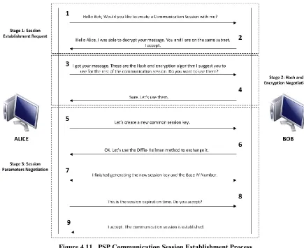
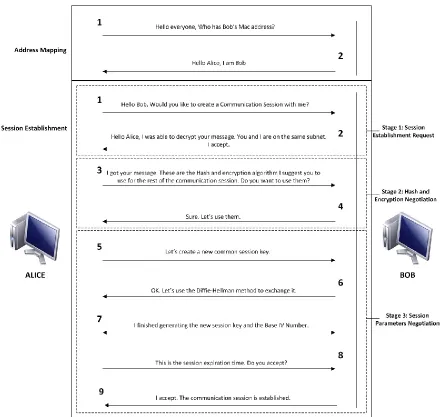
Figure 4.11. PSP Communication Session Establishment Process
Each step of the Communication Session Establishment is depicted in Figure 4.11.
Stage 1: Session Establishment Request
25
2. Bob verifies that Alice’s Network address is on the same subnet as his, and that the
destination address is Bob’s. If Alice and Bob are in different subnets, or if the destination address of the request sent by Alice is not Bob’s network address, Bob will drop the request packet and won’t reply to Alice. If both devices are in the same subnet, Bob will reply accepting the request.
Stage 2: Hash and Encryption Negotiation
If Bob accepts the communication session establishment request, Alice and Bob will negotiate the encryption and hashing algorithms to use from that point on.
3. Alice sends an offer of encryption and hashing algorithms to Bob.
4. Bob replies accepting or rejecting the offer. If both hosts agree upon which
encryption and hashing and algorithms to use, the session establishment process continues.
Stage 3: Session Parameters Negotiation
Once both hosts have agreed upon encryption and hashing algorithms for their communication, they negotiate a session key, a mathematical function to calculate the Initialization Vector of the encryption algorithm and a session expiration time.
5. Alice requests to establish a new common session key to encrypt future
communication.
6. Bob confirms the message and starts a key exchange using the Diffie-Hellman
method.
7. Once both Hosts have agreed upon a new common symmetric key, they calculate
the HMAC-SHA1 of the new key to generate the Base IV Number used to calculate the Initialization Vector.
8. Alice sends a session expiration time.
9. Bob replies accepting or rejecting the expiration time. From this point on, the
26
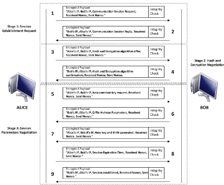
Figure 4.12. PSP Communication Session Establishment Process – PDU Structure
27
4.4.3. Session key Mapping
[image:41.612.99.519.392.654.2]
Figure 4.13. PSP Communication Process – Step 3
When two hosts establish a communication session, a unique symmetric key is
generated and an encryption and hashing algorithm, along with a mathematical function to calculate the IV are negotiated to protect the communication between them. Session key mapping is the association of the session key and communication session parameters with the Hardware address of a host based on the layer 2 protocol that is used in the
communication: Ethernet, HDLC, Frame Relay, PPP, etc.
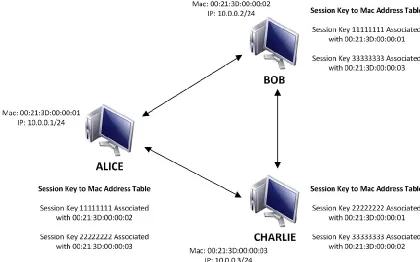
Figure 4.14. PSP Session Key Mapping
Address Mapping
Mapping
Session Establishment
28
Let’s say that Alice, Bob and Charlie use Ethernet as layer 2 protocol. Figure 4.14 shows that Alice has established a communication session with Bob and a second communication session with Charlie. Every time Alice receives a packet, she will know which session key and encryption and hashing algorithms must use to decrypt the packet because of the Hardware address of the sender (in this case, the Mac address). If the
packet’s source mac address is Bob’s, Alice will know that she will have to use the session key created with Bob and not the session key created with Charlie.
4.5. PSP Communication Process in an Ethernet Environment
This section explains the PSP communication process in an Ethernet environment. Let’s use the same example shown in section 4.4.1.1 where Alice wants to send a packet to Bob. Both hosts are using IPv4 or IPv6 but this time, they want to protect the
communication using PSP.
Figure 4.15. Data Processed Through the OSI Model with PSP Protection
Figure 4.15 depicts how PSP fits into the OSI layered model. The entire IPv4/6 datagram (header and payload) will be encapsulated into a PSP PDU without disclosing any kind of information about the packets being transmitted.
29
4.5.1. Address Mapping
Most of LAN networks today use Ethernet as layer 2 protocol. When a host is configured with IPv4 as Network protocol, it uses ARP to map network and hardware addresses. ARP supports the IPv4 protocol but is not part of it [22], and information about the source and destination network addresses is transmitted in clear text. To avoid
disclosing network address information, all ARP packets are encapsulated into PSP.
Figure 4.16. ARP Over PSP
As depicted in Figure 4.16, instead of directly broadcasting an ARP request in clear text asking for the Mac address of Bob, Alice will encrypt the ARP request using the default pre-shared key and will create a layer 2 frame with the Ethertype field as a PSP packet. All hosts in the same physical segment of the network will receive the packet and check the Ethertype field in the Ethernet frame, but only hosts protected by PSP and using the same default pre-shared key as Alice will be able to decrypt it. All hosts protected by PSP will first calculate the Integrity Check Value of the frame. If the calculated value is the same as the value in the ICV field of the received frame, they will proceed to decrypt and extract the payload. By default the PSP protocol uses Blowfish and HMAC-SHA1 as encryption and hashing algorithms.
Once the packet is decrypted, all hosts will extract the ARP request and only Bob will send an ARP reply encapsulated into PSP to Alice.
With PSP, hosts can map Mac and IP addresses in a secure way without disclosing IP information.
4.5.2. Session Communication Establishment and Session Key Mapping
30
including encryption and hashing algorithms, unique session symmetric key, Base Initialization Vector Number (BIVN), mathematical function to calculate the IV and communication session expiration time. After establishing a communication session, Alice and Bob can communicate with each other.
Alice and Bob will use Session Key Mapping to identify their communication session. Every time Bob receives a frame from Alice, he will know what session key and
encryption and hashing algorithms to use thanks to Alice’s Mac address.
If we look at the communication process from a security perspective, it is safe from Man-in-the-Middle attacks or eavesdropping. From the beginning of the communication, which starts off with the ARP request, all messages are encrypted. The only information that is disclosed are the layer 2 and PSP headers, but the communication messages and IPv4 header are completely encrypted.
31
Figure 4.17. Complete PSP Communication Process in an Ethernet Environment
32
5. IMPLEMENTATION OF THE PROPOSED SOLUTION
This section explains the methodology, scenarios, tested protocols and services, test categories and the computer program developed to demonstrate the proposed Packet Security Protocol.
5.1. Methodology and Scenario
We have developed a computer program in C++ to demonstrate the proof of concept of our proposed solution. This demonstration was based on a methodology consisting of a security and a performance analysis. First, we analyzed the security of our proposed protocol by performing different attacks to compromise the communication between two hosts, and later, we protected the same communication with our solution; we also analyzed the impact on security caused by the use of different modes of operation of a block cipher. Second, we ran multiple tests to 7 different protocols to measure the performance of the network and the performance of the hosts using our proposed solution.
The main objective of this methodology is to measure the security, performance and reliability of the Packet Security Protocol based on the following characteristics:
Data confidentiality: Verifies that the payload and IP headers are fully encrypted
and an attacker is not able to decrypt them or recognize data patterns.
Data integrity: Verifies that the Ethernet frame is not successfully modified by an
attacker.
Network performance: Reflects the network latency, data throughput and
bandwidth of the protocol.
System performance: Reflects the CPU and memory usage on the systems running
the proposed protocol.
33
Figure 5.1. Network Topology
Three virtual machines - a network protocol analyzer capturing traffic for data analysis purposes, one client and one server all running the proposed Packet Security Protocol - are connected to a virtual switch configured in promiscuous mode. An attacker not running the proposed Packet Security Protocol is connected to the same virtual switch and is sniffing the traffic of the network.
5.2. Security Analysis
We performed an ARP spoofing and Man in the Middle attack and installed an SSH honeypot to capture user credentials of the server. The scenario is the same depicted in Figure 5.1 but without protecting the network with our protocol. We later tried to replicate the same attacks to the network depicted in Figure 5.1 protected with our proposed
solution.
The second part of the security analysis evaluates the possible security implications derived from using our solution with a block cipher in Electronic Codebook mode (ECB).
5.3. Performance Analysis
34
5.3.1. Tested Protocols and Services
The following protocols and services were tested: ARP, ICMP, VoIP, Skype,
Iperf-TCP, Iperf-UDP and SCP.
For Skype tests, we used a different scenario as depicted in Figure 5.2.
Figure 5.2. Network Topology for Skype Tests
Host A establishes a Skype video conference with Host B. Host A is running the proposed Packet Security Protocol (PSP) and accesses the internet through a Linux router also running PSP. A network protocol analyzer also running PSP is capturing traffic for data analysis purposes. An Attacker is connected to the same virtual switch as the
Analyzer, Host A and the Linux Router, and it is sniffing the traffic. The virtual switch is configured in promiscuous mode.
5.3.2. Test Categories
The following test categories were used in this test methodology:
1- Ethernet without PSP applied. TOE disabled
The purpose of this category is to establish a baseline and a reference for all tests. Network protocols and services tested in other categories were compared to this one and reflected the network and system performance variation of the proposed Packet Security Protocol.
35
The network adapter of the Client and the Server had the TCP Offloading Engine (TOE), a feature of some network adapters to offload the TCP segments to the network adapter and improve cpu usage [23], disabled to mimic a regular network card. This is the most common scenario in today’s network environments.
Protocols and services tested under this category: ARP, ICMP, VoIP, Skype, Iperf-TCP, Iperf-UDP, SCP.
2- Ethernet without PSP applied. TOE enabled
In this category, all tests were conducted in a regular scenario where data is sent over the network with no encryption or manipulation of the payload, layer 3 or layer 2 headers. The network adapter had the TCP Offloading Engine (TOE) enabled.
TOE is an optional feature included in some Network adapters used to free up the CPU from processing the TCP segments and add significant performance improvements. The TCP Offload Engine has a complete TCP Stack to handle all TCP transport and IP addressing functions. [23]
The purpose of this category is to measure the impact of enabling vs disabling TOE on TCP related tests and how the advantages of enabling TOE are compromised by the proposed Packet Security Protocol. This includes CPU and bandwidth usage.
Protocols and services tested under this category: Iperf-TCP, SCP.
3- PSP-NoENC-NoHMAC
This category measures the impact on network and system performance due to using Packet Security Protocol without encryption and HMAC calculation. Even though, the proposed protocol is not meant to be used without encryption and HMAC calculation, this category shows the processing overhead caused by the program developed to prove the concept of Packet Security Protocol. The specific details of this program are explained in section 5.5
36
4- PSP Full
This category measures the real performance of Packet Security Protocol, just as
proposed in this thesis, with encryption and HMAC capabilities. The results of the tests run on this category show the real processing overhead added by the proposed protocol and the computer program developed to prove the concept of the protocol. The specific details of this program are explained in section 5.5
Protocols and services tested under this category: ARP, ICMP, VoIP, Skype, Iperf-TCP, Iperf-UDP, SCP.
Table 5.1. Protocols and Services Tested In Each Category
CATEGORY 1-Ethernet without PSP applied. TOE disabled 2-Ethernet without PSP applied. TOE enabled 3-PSP-
NoENC-NoHMAC 4-PSP Full
TEST
ARP X X X
ICMP X X X
Iperf-TCP X X X X
Iperf-UDP X X X
SCP X X X X
VoIP X X X
Skype X X X
Table 5.1 shows which protocols and services were tested in each category.
5.4. Hardware and Software Specifications
All tests were conducted on a virtualized environment. The following hardware and software was used:
Physical Machines Hosting the Virtual Machines
Due to the nature of some tests, we had to use two physical machines to host the virtual environment.
Cisco UCS-C220-M3 Server
o 2 x Intel(R) Xeon(R) CPU E5-2650 @ 2.0 Ghz
o 32 GB Ram
37
o Integrated dual-port Gigabit Ethernet
o VMware ESXi
Laptop HP Pavilion dv6-3236nr
o 1 x Intel(R) Core(TM) i3 CPU M370 @ 2.40 Ghz
o 4 GB Ram
o 128 MB OCZ Vertex3 SSD
o Integrated 1 port Gigabit Ethernet
o Windows 7 Professional x64
Virtual Environment
VMware ESXi 5.1.
o Used to test the following protocols and services: ARP, ICMP, Iperf-TCP,
Iperf-UDP and SCP.
o Hosted on Cisco UCS-C220-M3 Server.
VMware Workstation 9.0.
o Used to test the following protocols and services: VoIP and Skype.
o Hosted on Laptop HP Pavilion dv6-3236nr.
Virtual Machines
Each virtual environment had 4 virtual machines with the following specifications:
Virtual Environment VMware ESXi 5.1.
o 2 x vCPU Intel(R) Xeon(R) CPU E5-2650 @ 2.0 Ghz
o 4 GB Ram
o 1 x Gigabit Ethernet Interface
o Ubuntu Linux Desktop 12.04.2 LTS x64 Kernel 3.5.0-23-generic
Virtual Environment VMware Workstation 9.0
o 1 x vCPU Intel(R) Core(TM) i3 CPU M370 @ 2.40 Ghz
o 4 GB Ram
o 1 x Gigabit Ethernet Interface
38
Network Protocol
IPv4
Programs
Wireshark v1.6.7 for Linux: Wireshark is a cross-platform network protocol
analyzer used to capture and analyze network traffic [24].
Iperf v2.0.5 for Linux: Iperf is a network performance testing tool used to measure
TCP and UDP throughput [25].
SSH-2.0-OpenSSH_5.9p1: OpenSSH is a suit of computer programs that use the
SSH protocol to secure data communication [26].
Asterisk v11.3.0: Asterisk is a voice over IP telephony platform [27].
SIPp v3.2: SIPp is a tool used to test the SIP protocol [28].
Skype v4.1 for Linux: Skype is a real-time voice, video and text communication
application [29].
Ettercap NG-0.7.4.2: Tool used to perform ARP spoofing and Man in the Middle
Attacks [30].
Kippo-0.8: Kippo is an SSH honeypot that logs the user activity in an SSH session.
[31].
5.5. Developed Program
We developed a program in C++ to test the concept of the proposed Packet Security Protocol (PSP) on Ubuntu Linux using the following characteristics:
- Pre-shared Key
- Block Cipher Mode of Operation: Cipher-Block Chaining
- Encryption Algorithm: Blowfish
- Hash Algorithm: SHA-1
39
(CBC) mode as the encryption algorithm and calculates the HMAC value of the frame using the SHA-1 function.
Figure 5.3 shows a regular data transmission process in a Linux computer system. Data is generated by an application in the user space. The application passes the data to the kernel, where it handles the transport layer segmentation process, the network layer routing process and the data link layer framing process. The frames are then passed by the kernel to a network card of the computer for their transmission in a medium [32].
Figure 5.3. Regular Data Transmission Process
40
Figure 5.4. Data Transmission Process Using PSP
In a Linux environment, the virtual address space - a technique used to isolate a process in a unique address space - is divided in user space and kernel space. [33] User space is a reserved memory region used only for applications or user processes, and kernel space is the memory region reserved only for the kernel of the operating system [33]. An
application designed to run in user space tend to have slower performance than if it were developed to run in kernel space [34].
The way we developed the program doesn’t optimize the performance of the protocol. Data is created in the user space and then is passed to the kernel space. The program then adds a processing overhead by running in the user space and protecting the data with the Packet Security Protocol.
Figure 5.5. Block Diagram of the PSP’s Developed Program
41
Before going any further, it’s necessary to explain what a TUN/TAP driver and a TUN/TAP interface is.
The universal TUN/TAP driver allows packets and frames to be received by and delivered to a TUN/TAP interface, which is a virtual interface that only exists in the kernel of the operating system. One of the advantages of this kind of interfaces is that they can be attached to a user space program, and as a result, packets and frames can be easily
manipulated. TAP interfaces are used for Ethernet frames and TUN interfaces are used for IP packets. [35]
In the specific case of our developed program, from a data transmission perspective, the program uses the TUN/TAP driver to send frames to the TAP interface. As explained before, this interface only exists in the kernel and data can be easily received and
manipulated by a program. Once a frame is received in the TAP interface by the TAP Tx/Rx Module, it is passed to the Frame Formatting Module to extract the payload, add the PSP header and create a new frame with an Ether_Type field equals to 0x1982. Once the new frame is created, it is passed to the Encryption Module where only the network packet (header and payload) is encrypted. The new frame is then analyzed and gets its keyed hash message authentication code (HMAC) calculated by the HMAC Module. The fully
constructed data frame is then passed to the Ethernet Tx/Rx Module where it is sent to the network card.
From a Data reception perspective, the network card receives the PSP protected data frames that are sent over the network. The Ethernet Tx/Rx Module detects these frames incoming from the network card and passes them to the HMAC Module where they get their keyed hash message authentication code calculated and compared with the value attached to the HMAC field of the PSP protected frame. If both HMAC values are the same, the frame is passed to the Decryption Module where the network packet (header and payload) is decrypted. The frame with the decrypted packet is passed to the Frame
42
For the development of the program, we used the Crypto++ library for the encryption, decryption and HMAC functions used in the respective modules.
In section 5.3.2, we mentioned a test category of the Packet Security Protocol with no Encryption and no HMAC. For that purpose, we modified the developed program and disabled the Encryption, Decryption and HMAC modules, resulting in a block diagram as shown in figure 5.6.
43
6. TEST RESULTS
In this section we present a security and a performance analysis of the proposed Packet Security Protocol (PSP) based on the results obtained from the different tests we ran to our developed program. The security analysis demonstrates the efficiency of our solution at protecting the IP packets, while the performance analysis shows how the performance of the network and the host running the protocol is impacted.
6.1. Security Analysis
This security analysis explores if known network attacks can be avoided using our solution. It also examines the possible security implications derived from using our solution with a block cipher in Electronic Codebook mode (ECB).
6.1.1. ARP Spoofing and Man in the Middle Attack
We performed an ARP spoofing and Man in the Middle attack to route the traffic of the affected hosts to an SSH honeypot installed in our attacking station and capture user
credentials of the real server. The network topology is depicted in Figure 5.1, section 5.1. This attack was performed against an unprotected network to prove how vulnerable a wired Ethernet network can be; we later performed the same attack to the network protected with our solution to test if the attack can be avoided.
6.1.1.1. Anatomy and Results of the Attacks
First, we ran WireShark to sniff the network and discover the IP addressing scheme based on ARP broadcast messages. Next, we started Kippo, an SSH honeypot, in our attacking station. With the SSH honeypot up and running, we used Ettercap to sniff the network and perform an ARP poisoning and Man in the Middle attack against the discovered machines which, in this case, are a client and an SSH server.
44
Figure 6.1. User Credentials Captured in our SSH Honeypot
The user credentials were successfully captured, as shown in Figure 6.1.
6.1.1.2. Protecting the Network with Our Solution
We protected the network with our solution and tried to replicate the same ARP poisoning and Man in the Middle attacks. The frames captured by WireShark from our attacking station didn’t disclose any useful information that would allow us to detect the encapsulated protocols or the IP addressing scheme of the network. The client and the server machine, when running our proposed protocol, only understood traffic that was protected with our solution and not regular traffic in clear text.
It was impossible for us to replicate the attacks on the hosts protected with our Packet Security Protocol.
6.1.2. Vulnerabilities Derived From a Block Cipher in Electronic Codebook Mode
For this study, we captured an ARP-ICMP communication between a client and a server protected with our proposed protocol. It is important to note that this analysis doesn’t include ways to decrypt or tamper the communication session between both hosts, but it examines the structure of the captured frames and presents how a block cipher in ECB mode can affect the effectiveness of our protocol and make the protected data vulnerable.