1
Recent developments of the Linear Matching Method Framework for structural
integrity assessment
Daniele Barbera1, Haofeng Chen1, 3, Yinghua Liu2, Fuzhen Xuan3
1
Department of Mechanical & Aerospace Engineering University of Strathclyde, Glasgow, G1 1XJ, UK
2 Department of Engineering Mechanics,
Tsinghua University, Beijing, 100084, China
3 School of Mechanical and Power Engineering,
East China University of Science and Technology, 130 Meilong Road, Shanghai, 200237, China
Corresponding author: Haofeng Chen, [email protected]
ABSTRACT
The LMM subroutines and plug-in tools for structural integrity assessment are now in extensive use in
industries for the design and routine assessment of power plant components. This paper presents a
detailed review and case study of the current state-of-the art LMM direct methods applied to the
structural integrity assessment. The focus is on the development and use of the LMMF on a wide range of
crucial aspects for the power industry. The LMMF is reviewed to show a wide range of capabilities of the
direct methods under this framework, and the basic theory background is also presented. Different
structural integrity aspects are covered including the calculation of shakedown, ratchet and creep rupture
limits. Furthermore, the crack initiation assessments of an un-cracked body by the LMM are shown for
cases both with and without the presence of a creep dwell during the cyclic loading history. Finally an
overview of the in house developed LMM plug-in is given, presenting the intuitive Graphical User Interface
developed. The efficiency and robustness of these direct methods in calculating the aforementioned
quantities are confirmed through a numerical case study, which is a semi-circular notched (Bridgman
notch) bar. A 2D axisymmetric finite element model is adopted, and the notched bar is subjected to both
cyclic and constant axial mechanical loads. For the crack initiation assessment, different cyclic loading
conditions are evaluated to demonstrate the impact of the different load types on the structural response.
The impact of creep dwell is also investigated to show how this parameter is capable of causing in some
cases a dangerous phenomenon known as creep ratcheting. All the results in the case study demonstrate
the level of simplicity of the LMMs but at the same time accuracy, efficiency and robustness over the more
complicated and inefficient incremental finite element analyses.
2
Keywords: Linear Matching Method (LMM), Structural Integrity, Cyclic Plasticity, Cyclic Enhanced Creep,
Notched Bar
1. Introduction
Structural integrity assessment is a crucial aspect for conventional and nuclear power industries, and has a remarkable impact on the latter one. Subsequent efforts have been made in order to solve new emerging issues, since at the beginning of the commercial nuclear power era, with the Calder Hall grid connection in 1956. Structural integrity has played an important role due to the increasing aging of the power plants, and the aging of material increased more concerns on the safety of reactor components. Different problems due to the aging have been encountered, such as the Reactor Pressure Vessel embrittlement for the UK Magnox reactor, the graphite core cracking and the crack initiation of the boilers weldment [1] in the Advanced Gas-cooled Reactors (AGR). Due to the necessity of minimizing the distance between the heat source and the machineries necessary to transform the heat into electricity, reactors are compactly assembled with a limited access. In the typical AGR some key components are embedded around the reactor core, making the access to these components difficult. For these reasons inspections must be planned ahead, and the structural integrity assessment is a valuable tool in identifying critical components in time.
International design and assessment codes including ASME Boiler and Pressure Vessel Code (NH) [2] and the R5 procedure [3] are used to design and assess power plant components, and are always under development in order to improve their capabilities. However, these design codes have limitations in anticipating unknown phenomena, such as the remarkable material degradation or the effect of secondary loads on the fatigue life and stress corrosion. Furthermore, they are rule-based methods, and rely on elastic finite element analyses that may produce very conservative results. Although inelastic analyses may be used in order to relax the aforementioned conservatism, they are computationally inefficient and not always practicable. This can be an issue when a life extension program is going to be undertaken, which requires a much deeper understanding of all the possible failure mechanisms. For this purpose not only a detailed material description is necessary, but also it is essential to have a more accurate, robust and efficient methodology for calculating the structure response under complex cyclic loading condition.
3
has been introduced by [8]. For a given cyclic loading condition the eDSCA is capable of considering a full creep-fatigue interaction during the cycle to enhance the R5 procedure. As many other direct methods the LMM is developed into commercial finite element software ABAQUS by FORTRAN user subroutines [9], which induced a bottleneck for the adoption of the method by industries. For this reason a Graphical User Interface (GUI) is recently created by adopting the ABAQUS CAE plug-in [10, 11]. This approach allows even non-experienced user to run LMM analyses without the necessity to work directly with the source code.
In this paper the UK’s R5 procedure for the evaluation of high temperature response of structures is reviewed. Consequently, a discussion on how all the features of the LMMF can be used to enhance the R5 procedure is presented, showing for the first time all the capabilities and the background of the method to perform the life assessment of a component. Furthermore, the recent advancements in the GUI and ABAQUS plug-in development are outlined. Finally a numerical case study example is presented to show the accuracy and efficiency of the entire framework.
2. The R5 assessment procedure
The R5 procedure [3] for the evaluation of high temperature response of structure has a series of crucial assessments required for life prediction of a component. The procedure in volumes 2 and 3 provides assessment methods to a defect-free component, and the lifetime must be evaluated against the following mechanisms:
Plastic collapse failure mechanism
Creep rupture failure mechanism
Ratcheting or incremental inelastic collapse
Crack initiation due to creep-fatigue interaction
Excessive cyclic enhanced creep deformation
The aforementioned failure modes are assessed by simplified rule based methods, which do not require full inelastic analyses. The structure must be capable of bearing the applied load without suffering a plastic collapse during the first application of the load cycle. Furthermore, it is fundamental that the linear stress components do not cause extremely large plastic strain deformation before reaching the steady state cycle. The maximum range of equivalent elastic stress, calculated by considering the combined action of both primary and secondary loads, must not be greater than the product of a safety factor and the yield stress of the material, or an average when non-isothermal load cycles are considered [3]. This kind of approach inevitability produces over conservative results, in particularly when linearized stresses are adopted.
If creep is not negligible creep rupture limit needs to be assessed. In the R5 procedure the creep rupture assessment is based on the calculation of a reference rupture stress. Different formulations can be adopted depending on the creep ductility of the material. However this approach is based on the reference stress technique and the knowledge of the shakedown limits. Both the creep rupture procedure and the calculation of the shakedown limit are conservative, in particularly when non-isothermal condition and nonlinear geometry are considered, as shown by [12] for an holed plate case.
4
condition cannot be satisfied, a more detailed analysis using a constant residual stress field must be used. Both calculations for the elastic and plastic shakedown limits used in the R5 procedure are based on the post processing of linear elastic solutions, which are very conservative.
The Low Cycle Fatigue (LCF) assessment concerning the crack initiation life in the R5 procedure adopts approximated methods, such as Neuber’s approximation to evaluate the plastic strain ranges. The Neuber’s rule has been demonstrated to be very conservative, especially when thermal stress dominates. Furthermore, when creep must be considered during the load cycle, the R5 procedure does not consider full creep-cyclic plasticity interaction in the model to assess the steady state cycle. However this interaction may be crucial, and without the full consideration of interaction between creep and cyclic plasticity, cyclically enhanced creep, creep enhanced plasticity and creep-ratcheting mechanisms cannot be properly addressed.
3. The Linear Matching Method Framework
The R5 procedure is composed of several steps, which need to be completed in order to fully assess the integrity of a component. A schematic flowchart is presented in Fig. 1 to show the R5 procedure [13] for structural integrity assessment of defect-free components and LMMF capabilities in support of it.The main objective of the LMMF is to evaluate key design limits and parameters required in the R5 procedure in an efficient and accurate way by various of direct methods. In comparison with full inelastic analysis, which needs detailed material constitutive equations and load histories, the direct methods in the LMMF do not have high computational cost and inherent convergence issues of detailed step-by-step analysis. It can be seen from Fig. 1 that the direct methods within the LMMF are able to assess safe margins against the plastic collapse and creep rupture, if creep is significant, in an accurate and efficient way, without relying on conservative assumptions or complex constitutive formulations. As depicted in Fig. 1 the LMMF also provides numerical procedures to calculate both shakedown and ratchet limits for any arbitrary load history, providing upper and lower bound solutions. When creep is relevant, but the associated dwell time is too short to have a stress relaxation, the overall load history involving a constant residual stress filed is similar to shakedown condition. For this case, the LMMF provides a rapid cycle creep analysis to calculate the creep strain rate for each load cycle, which is more accurate than the R5 procedure [12]. In order to evaluate the pure fatigue and creep-fatigue damages, the LMMF provides DSCA and eDSCA to estimate the steady state cycle, considering pure plasticity or full creep and cyclic plasticity interaction, respectively. The creep-fatigue damage can be assessed by the obtained total strain and stress ranges of the steady state cycle, the start of dwell stress, the associated stress drop and creep strain during the creep dwell. This approach is different from the R5 procedure, which relies on approximations to calculate the aforementioned quantities. Hence, the use of the LMMF safely reduces conservatisms, but also improves the understanding of the cyclic response of the structure by characterizing complex mechanisms such as creep-ratchetting or cyclically enhanced creep.
To better understand the basic theoretical background of the LMM, we assume an Elastic Perfectly Plastic (EPP) body with a volume V and a surface S. The volume V of this body is subjected to a varying temperature and mechanical load acting over the structure’s surface ST, leaving the remaining surface
constrained to have no displacement. The time variation considered over a typical cycle is 0 Dt t. Corresponding to these loading histories a linear elastic stress history
ˆ ( , )
eij
x t
s
exists:ˆ
s
ije(
x
,
t
)
s
ˆ
ij(
x
,
t
)
ps
ˆ
ijp5
where
s
ˆ
ij ands
ˆ
ijp denotes the varying elastic stresses due to the cyclic temperature and mechanicalload respectively. By selecting the proper multipliers of
and
pa whole class of loading histories canbe considered. The general stress field for the cyclic problem involves three different components; the elastic stress, the constant residual stress field and a changing residual stress fields. For the aforementioned assumptions, it is able to express the cyclic stress history with three separate terms as follow:
ˆ
( , )
e( , )
( )
r( , )
ij
x t
ijx t
ijx
ijx t
s
s
r
r
(2)where
ˆ ( , )
e ijx t
s
represents the cyclic linear elastic stress history depicted in equation (1),r
ij( )
x
denotesthe constant residual stress field which is in equilibrium with zero primary loading and corresponds to the
residual stress field at the start and end of the cycle, and r
( , )
ij
x t
r
represents the changing residual stressfield within the load cycle. Depending on the design problem the cyclic stress history represented by equation (2) can be simplified. For elastic shakedown and creep rupture analyses, the changing residual
stress field is neglected otherwise
r
ijr(
x
,
t
)
¹
0
must be considered.
In order to characterize the critical design limits mentioned in the previous section and the steady state cyclic response, dual minimization processes of a functional with an appropriate class of
kinematically admissible strain rate history are carried out within the LMMF. The global minimization
process is adopted for the cyclic problems, such as the shakedown problem, that only involves a constant residual stress field [5]. In addition to this, an incremental minimization process is performed to evaluate a steady state cycle that involves a changing residual stress history. If a closed loop steady state cycle is obtained the changing residual stress field occurring during the entire cycle needs to be zero. When the contribution of constant and changing residual stress field are minimized the steady state is considered to be reach. This incremental minimization process is summarized as follow:
(3)
I
nD
ijn,
s
ijnD
ijn-
s
ˆ
ije(
x
,
t
n)
r
ij(
x
)
r
ijr(
x
,
t
n)
é
ë
ù
ûD
ijn
{
}
V
ò
dV
(4)r
ijr(
x
,
t
n)
D
r
ij l1n
å
t
l (5)where N represents the total number of load instances considered within the load cycle and
r
ijr(
x
,
t
n)
isthe summation of all the previous changing residual stress increments
D
r
ij
t
l . The strain rate history isreplaced by a series of strain increments
D
ijn(or
D
ij(
t
n)
), as shown in equation (4) and (6), that occurs6
D
ij,l1(
t
n)
'
1
2
l(
t
n)
s
ˆ
ije
(
t
n)
r
ijr,l1(
t
n-1)
D
r
ij,l1(
t
n)
é
ë
ù
û
'
D
kk,l1(
t
n)
0
(6)
where notation ( ' ) refers to the deviator component of stresses and
l( )
t
n is the iterative shearmodulus obtained from the lth iteration. This iterative shear modulus is obtained by the following linear matching equation:
l1
x
,
t
n
l
x
,
t
n
s
yR
(
x
,
t
n)
ls
s
ˆ
ijex
,
t
n
r
ijrx
,
t
n
l
(7)where
l1
x t
,
n
is the iterative shear modulus at the iteration l+1 for nth load instance andr
ijr
x t
,
n l
is the sum of the constant residual stress field and all the previous changing residual stresses at load
instance
t
n. It is worth noting thats
yR(
x
,
t
n
)
l is the revised iterative von-Mises yield stress at loadinstance
t
n, and this allows the LMMF to adopt both the Elastic Perfect Plastic model andRamberg-Osgood formula to consider cyclic hardening or softening behaviours of materials. When a high
temperature creep dwell is introduced at the load instance
t
nduring the load cycle, the revised yieldstress
s
yR(
x
,
t
n)
lbecomes the minimum of the yield stress and creep flow stress at the load instancet
nfor creep calculation. The entire numerical procedure is described in detail in [8], and it involves an iterative procedure for the calculation of the stress field at start and at the end of the creep dwell, the associated creep strain and creep strain rate.
4. The LMM software tool
7
by using individual load or temperature field defined in the CAE. This approach allows the user to consider a whole class of different loading conditions. Once the load history is defined the desired convergence rule can be selected (Fig. 2d). The maximum number of increments and the name of the analysis file can be decided to generate a successful LMM job. It is worth noting that the LMM software tool has the capability to perform multiple Computer Processing Units (CPUs) analysis. This feature is very important for the large model when 3D complex geometries are considered.
5 Case study: Notched bar
In order to show the capabilities of the LMMF, a benchmark numerical example is presented. The stress distribution in real industrial components can be very complex due to the presence of stress concentrators, change of thickness or groves. For this reason in order to test the accuracy of the method a notched bar has been selected. A bar with a gross radius of 5 mm, a gauge length of 25 mm and a circumferential round notch radius of 2.5 mm is considered, as shown in Fig. 3a. Due to the symmetry of the problem an axisymmetric model is adopted. The mesh is composed of 336 quadratic quadrilateral elements CAX8R, with a reduced integration scheme. Both the cyclic and constant mechanical loads are applied and their loading histories are shown in Fig. 3b.
D
s
is a cyclic axial load with R=-1, ands
m is a constant load. The bar is exposed homogeneously to a high and constant temperature of 550 °C. This type of loading condition allows for the consideration of a large number of different loading histories. For creep-fatigue interaction study a hold timeD
t
is considered at the tensile peak, where significant creep damage is expected. The material used for this example is stainless steel 316L(N), and all the elastic and inelastic material properties are presented in Table 1. The saturated cyclic plastic behavior is modeled using the well-established Ramberg-Osgood relationship:1
'
2
2
E
B
s
s
D
D
D
(8)where
D
2
is the total strain amplitude,D
s
is the total stress range,'
B
and β are material parameters.These parameters are extrapolated by the locus of tips obtained from low cycle fatigue tests covering a wide range of total strain amplitudes. In order to model the high creep the Norton-Bailey relationship is used and it is defined as follow:
(9)
where ,
s
and t are the equivalent creep strain rate, equivalent stress and time, respectively, and B, n and m are material parameters.5.1 Numerical results for cyclic response, plastic collapse and creep rupture
8
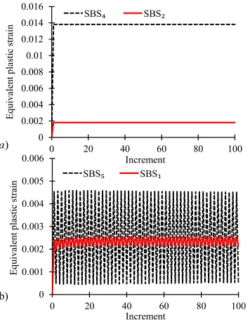
ratchet limit and limit load by a dashed dot green and violet line respectively. When subjected to a cyclic load within the shakedown limit the response of structure becomes Elastic Shakedown (ES), where the material responses totally elastically except for an initial plastic strain occurred at the beginning of load cycle. If the component operates in the Plastic Shakedown (PS) region low cycle fatigue is expected and a closed loop cycle is present. Contrary to the Bree-like diagram for a cycling thermal load and a constant mechanical load, the ratchet limit and the limit load are coincident as shown in Fig. 4. This is due to the presence of a cycling and a constant primary loads, which make ratchet limit and limit load identical. The results obtained provide a clear picture of the cyclic behavior of the structure, for different magnitudes of the loads applied. To demonstrate the accuracy of the limits predicted a series of Step-by-Step (SBS) analyses have been performed for six cyclic load points shown in Fig. 4. Fig. 5a presents the obtained plastic strain magnitude histories for the cyclic load points SBS2 and SBS4. Both cyclic load points exhibit a
clear shakedown behavior. Fig. 5b shows calculated plastic strain magnitude histories for the cyclic load points SBS1 and SBS5, both exhibiting a reverse plasticity behavior. The analyses for the last two cyclic load
points SBS3 and SBS6 aborted before completing. Both the cyclic load points are over the limit load, hence
it is impossible to meet the equilibrium. These results from the SBS analyses demonstrate the accuracy of the shakedown limit, and ratchet limit (limit load) prediction obtained by the LMM. Furthermore, it is worth nothing that the computational cost required by incremental analyses is much higher than the LMM. For the shakedown and ratchet analysis, the advantage of the LMM over the SBS is that the LMM is a direct method that exploits the bounding theorems and is able to calculate the limits directly and accurately. Instead, the SBS analysis needs a significant number of trials and error to locate these limits. Indeed a single SBS calculation can only determine whether the component is in shakedown or ratcheting. When the component is subjected to an elevated temperature the creep rupture limit need to be assessed. For this purpose, the LMM has been recently extended in order to accurately calculate the rupture limit for the desired rupture time, by an extended shakedown procedure, as used in the R5 procedure, but in a much more accurate and robust way. In the LMM creep rupture analysis, the steady state cyclic stress is accurately evaluated by considering the associated residual stress at each integration point. And moreover, the temperature dependent creep rupture stresses are also considered for the entire structure without any conservative assumptions. In Fig. 4, two creep rupture limits are shown for 10000 (short dash) and 100000 (long dash) hours. In this assessment, the reduction of material strength across the entire specimen is homogeneous due to the constant and homogenous temperature. For the aforementioned reasons the most critical location is always located at the root of the notch. If the applied cyclic loading point is outside the creep rupture limit, the component will rupture in an earlier stage of its designed life.
5.2 Low cycle fatigue and creep fatigue life assessment
9
the LCF assessment with creep-fatigue interaction, three tensile peak dwell periods of 1, 10 and 100 hours are considered. A series of parameters is required to fully assess the creep-fatigue interaction, which leads to the crack initiation at the most critical location. These parameters are discussed by [14], and are the total strain range, the stress at the start of the dwell, the creep stress drop, the associated equivalent creep strain increment and the elastic follow up factor. Contrary to the R5procedure, which bases on the calculation of many of the aforementioned parameters on a series of approximate quantities obtained by the elastic solution, the LMM fully considers the creep-fatigue interaction during the cycle and accurately calculates the equivalent elastic, plastic and creep strains and associated stresses by adopting robust solid mechanics concepts. Fig. 6 shows the results of the pure fatigue and creep-fatigue assessment of the specimen subjected to the cyclic loading points A, B and C shown in Fig. 4. A visual comparison of the number of cycles to failure between those predicted by the Neuber’s rule (dashed and solid square), the predicted by the LMM (red dot), and by the SBS (green star) adopting a nonlinear kinematic hardening for different total strains is shown in Fig. 6. Since experimental results for the specific geometry and testing temperature are not available, experimental results obtain by [15] for a similar geometry at higher temperature are reported. The results obtained for the Neuber’s rule tends to overestimate the fatigue endurance of the notched bar as expected. The results obtained by the LMM and SBS are both consistent with the experimental available at higher temperature and concentration factor.A good agreement is achieved for the pure fatigue predictions between the SBS and LMM, especially for intermediate and large strain ranges (cyclic load point B and C). The SBS analyses are slightly less conservative for the all the strain ranges considered. However, the CPU time required by the SBS analysis is around 1104 seconds, instead only 116 seconds for the LMM adopting the Ramberg-Osgood material model. The SBS requires 16650 increments to complete all the 150 steps, instead the LMM needs only 150 increments for the single analysis step
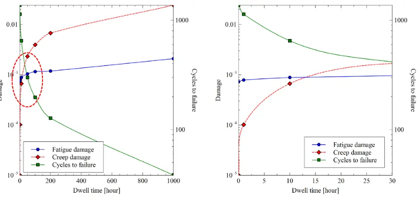
The impact of creep dwell on the life of the specimen is investigated, and it is also shown in Fig. 6. The creep-fatigue assessment results are presented for the three dwell times considered. For 1 hour dwell the life reduction is around 42%, and the damage due to fatigue is larger but comparable to the one produced by creep. However, when the creep dwell increases creep-fatigue interaction becomes relevant and the life reduction is more significant. The further stress relaxation due to the increase of the dwell time enhances the reversed plasticity during the reverse loading. Fig. 7 shows how the cyclic response is affected by the increase of the creep dwell. The effect of creep-fatigue interaction on the notched bar life is shown in Fig. 8, for cyclic load point A (0.25 % applied strain amplitude) at different dwell times. From the plot on the left the creep damage increase with the dwell time, and after a precise threshold it is larger than the fatigue damage. Despite the stress relaxation, the fatigue damage is not enhanced significantly. The hardening allowed by considering the Ramberg-Osgood material model allows better prediction of the reversed plasticity. By focusing on the same figure up to 30 hours a turning point can be identified, which is about 10 hours. Between 10 and 15 hours, the creep-fatigue interaction is highest, after 15 hours the creep damage increases and becomes the most important failure mechanism.
10
produce significant damage compared to creep-fatigue interaction. The expected failure is at 98 cycles, but the creep-fatigue cycles to failure have been estimated to about 40 cycles.
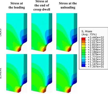
To validate the results obtained a detailed Step-by-Step analysis has been performed for the same loading case, considering a dwell time equal to 1 hour. Same material models have been used, considering elastic-plastic-creep materials. A visual comparison between the stress field predicted by the LMM and the SBS is shown in Fig. 10. For each load case considered the stress field predicted by the LMM is significantly similar to that one calculated by the SBS. The effects of plasticity, creep and stress relaxation are fully replicated by the LMM, demonstrating its high effectiveness. Furthermore, in Table 2 a detailed comparison between LMM and SBS is proposed. The stress and strain predicted at the most critical location are showed for each load instance. The results predicted by the LMM are always very close to those predicted by the incremental finite element analysis. It worth noting, that the computational time required by the LMM is smaller than the traditional SBS. The LMM takes 165 seconds to calculate the steady state cycle response against the 3345 required by the SBS. This important feature is made possible by the direct calculation of the steady state cycle, which requires for this case study 150 steps and 150 increments. Conversely, SBS requires more than 20000 increments to reach the stabilized cycle. Furthermore, the LMM computational cost is not affected by the creep dwell length and it always requires a computational cost of about 200 seconds. Instead, the SBS analysis requires more computational time when the creep dwell increases. This final outcome shows how the eDSCA analysis is a useful tool for creep-fatigue crack initiation assessment of complex multiaxial problems.
6 Conclusions and future works
A complete overview of the Linear Matching Method Framework is presented. An introduction of both the LMMF numerical procedures and the user GUI plug-in software tool is given, demonstrating respectively its flexibility and enhanced accessibility to a wide range of users, including those who have little knowledge in theory and programming skills.
The benchmark example of the notched bar demonstrates the effectiveness and accuracy of the method. Different analysis types are achieved with the minimum number of material properties. For the shakedown, ratchet, and limit load analyses only elastic properties and the yield stress of the material are required, when considering the EPP model. For the ratchet limit analysis, the Ramberg-Osgood model can also be adopted to consider cyclic hardening or softening of the material. The accuracy of the limits provided has been verified by detailed Step-By-Step analyses.
For the evaluation of the steady state cycle the LMMF can consider either an EPP material model or the Ramberg-Osgood model in order to consider cyclic material hardening. When high temperature creep dwell occurs, the Norton-Bailey creep law has also been implemented within the LMMF through an extended DSCA for the full consideration of the creep-fatigue interaction during the load cycle. The method has been capable of identifying dangerous mechanisms including creep-ratchetting for long dwell time. For the creep and fatigue interaction the LMMF through the eDSCA delivers a flexible and efficient solution, crucial for more complicated problems involving multi-materials and 3D geometries.
In future the method will be enhanced by implementing more creep constitutive equations including the strain hardening formalism, which is also widely adopted as the time hardening. Furthermore, during the creep dwell a non-constant elastic follow up factor will be considered developing a more accurate numerical procedure for the evaluation of the creep dwell.
11
The authors gratefully acknowledge the support of the University of Strathclyde, the East China University of Science and Technology, the Royal Academy of Engineering, the Royal Society (IE140842), the International Cooperation and Exchange Project NSFC (11511130057) and the National Science Foundation for Distinguished Young Scholars of China (11325211) during the course of this work.
References
[1] O’Donnell, M., Bradford, R., Dean, D., Hamm, C., and Chevalier, M., "High temperature issues in advanced gas cooled reactors (AGR)," Proc. In TAGSI/FESI Symposium: Structural Integrity of Nuclear Power Plant.
[2] The American Society of Mechanical Engineers, 2013, ASME boiler & pressure vessel code : an international code, Division 1 - Subsection NH.
[3] EDF Energy, 2014, Assessment procedure for the high temperature response of structures, R5 Issue 3. [4] Chen, H., Ure, J., and Tipping, D., 2013, "Calculation of a lower bound ratchet limit part 1 – Theory, numerical implementation and verification," European Journal of Mechanics - A/Solids, 37, pp. 361-368. [5] Chen, H., 2010, "Lower and Upper Bound Shakedown Analysis of Structures With Temperature-Dependent Yield Stress," Journal of Pressure Vessel Technology, 132(1), p. 011202.
[6] Lytwyn, M., Chen, H., and Martin, M., 2015, "Comparison of the linear matching method to Rolls Royce's hierarchical finite element framework for ratchet limit analysis," International Journal of Pressure Vessels and Piping, 125, pp. 13-22.
[7] Lytwyn, M., Chen, H. F., and Ponter, A. R. S., 2015, "A generalised method for ratchet analysis of structures undergoing arbitrary thermo-mechanical load histories," International Journal for Numerical Methods in Engineering, 104(2), pp. 104-124.
[8] Chen, H., Chen, W., and Ure, J., 2014, "A Direct Method on the Evaluation of Cyclic Steady State of Structures With Creep Effect," Journal of Pressure Vessel Technology, 136(6), pp. 061404-061404.
[9] Hibbitt, D., Karlsson, B., and Sorensen, P., 2012, "Abaqus 6.12. 3 Manual."
[10] Ure, J., Chen, H., and Tipping, D., 2014, "Integrated structural analysis tool using the linear matching method part 1 – Software development," International Journal of Pressure Vessels and Piping, 120–121, pp. 141-151.
[11] Chen, H., Ure, J., and Tipping, D., 2014, "Integrated structural analysis tool using the Linear Matching Method part 2 – Application and verification," International Journal of Pressure Vessels and Piping, 120– 121, pp. 152-161.
[12] Chen, H. F., Ponter, A. R. S., and Ainsworth, R. A., 2006, "The linear matching method applied to the high temperature life integrity of structures. Part 1. Assessments involving constant residual stress fields," International Journal of Pressure Vessels and Piping, 83(2), pp. 123-135.
[13] Sauzay, M., Mottot, M., Allais, L., Noblecourt, M., Monnet, I., and Périnet, J., 2004, "Creep-fatigue behaviour of an AISI stainless steel at 550 °C," Nuclear Engineering and Design, 232(3), pp. 219-236. [14] Barbera, D., Chen, H., and Liu, Y., 2015, "On Creep Fatigue interaction of components at elevated temperature," Journal of Pressure Vessel Technology.
12
Table Captions
Table. 1 316L(N) mechanical properties at 550 °C from [12]
Table. 2 Results obtained from the comparison between the LMM and SBS analyses, for the
13
Table 1 316L(N) mechanical properties at 550 °C from [12]
Young’s modulus [MPa] 160000
Poisson’s ratio 0.3
Yield stress
[MPa] 270
Ramberg-Osgood B’ = 1741.96 β = 0.29960
Norton-Bailey B = 6.604∙10-19 n = 5.769 m =
-0.55
Table 2 Results obtained from the comparison between the LMM and SBS analyses, for the most critical location.
von Mises equivalent stress at loading
[MPa]
von Mises equivalent stress after creep dwell
[MPa]
von Mises stress equivalent at unloading [MPa]
Computational cost [sec]
LMM 336.7 312.2 336.7
LMM 165
SBS 330.2 309.7 334.6
Equivalent plastic strain loading
Equivalent creep strain at the end of
the creep dwell
Equivalent plastic strain at unloading
SBS 3345
LMM 8.005E-3 4.354E-4 8.291E-03
[image:13.612.102.514.259.422.2]14
Figure Captions
Fig. 1 Schematic flowchart showing the R5 procedure for structural integrity assessment and
LMMF capabilities in support of it.
Fig. 2 a) LMM main menu for analysis type and model selection, b) material properties
selection, c) load cycle construction menu, d) analysis parameters and convergence
methods and level menu.
Fig. 3 a) Schematically representation of the circumferential notched bar, b) different loading
histories considered.
Fig. 4 Notched bar interaction diagram, shakedown, ratchet and creep rupture limit.
Fig. 5 Plastic strain magnitude histories for different cyclic loading points obtained by
Step-by-Step analyses.
Fig. 6 Results for pure fatigue and creep-fatigue assessment of a circumferential round
notched bar with pure fatigue life curve.
Fig. 7 a) Cyclic response at different creep dwells time for cyclic loading point A at the most
critical location.
Fig. 8 Creep and fatigue damages against dwell time, and cycles to failure for the notched bar.
Fig. 9 Creep-ratcheting interaction diagram at different creep dwells for cyclic loading point A
at the most critical location, and contour of the cycles to failure for creep-ratcheting at
1000 hours.
Fig. 10 von Mises stress contour of the notched bar at different load instances, for the LMM
15 Problem description by defining service load
and temperature history, and material data.
Linear Elastic FEA and Thermal Analyses.
Creep is significant? yes
Creep rupture analyses using reference stress
Shakedown analysis by considering residual stress field
no
Determination of rapid cycle creep deformation without any relaxation during
hold periods.
Demonstrate sufficient margins against plastic collapse. yes no Inelastic Analyses Creep rupture life
Elastic or plastic shakedown?
LMMF
Elastic solution input for LMMFLimit load calculation based on simplified shakedown method
Creep rupture limits based on extended shakedown analysis
Shakedown and ratchetting limits for a whole class of loading
conditions
Plastic Limit load
LMM can be used to replace full inelastic analyses.
Rapid cycle
creep strain rate Rapid cycle creep analysis
Output from the R5. R5 Procedure
step.
Assessment of fatigue by evaluation the total strain range. Plastic strain is based on Neuber method. All quantities are based on elastic
analyses.
Creep is significant?
yes
Assess the creep damage occurred during the creep dwell based on elastic follow up factor, stress relaxation, creep strain accumulation
Combine Fatigue and Creep damage using the linear damage summation no
Assessing the stead state cycle by using DSCA. Fatigue life calculated for whole component, Ramberg Osgood available.
Fatigue endurance based
on total strain
Several parameters, Z factor, Stress drop,
creep strain
Creep-Fatigue Life of the most critical
location. End
LMMF (eDSCA) provides full creep-fatigue interaction and more accurate
parameters.
eDSCA considers full creep cyclic plasticity interaction and produces the number of cycles
to failure for the entire component
LMMF allows identifying many dangerous structural responses,
such as Creep Ratchetting.
Compare creep ratchetting life with creep-fatigue life.
no
no
[image:15.612.90.524.70.544.2]no
16 )
a b)
c) d)
[image:16.612.90.521.69.396.2]17
s
D
time
time
m
s
t
D
)
a
b)
m
s
s
D
[image:17.612.143.476.83.426.2]18
0.00
0.10
0.20
0.30
0.40
0.50
0.60
0.70
0.80
0.90
1.00
0.00
0.10
0.20
0.30
0.40
0.50
0.60
0.70
0.80
Shakedown limit
Ratchet Limit
Limit Load
Creep Rupture 10 khrs
Creep Rupture 100 khrs
A
B
C
SBS
₁
SBS
₂
SBS
₃
SBS
₄
SBS
₅
SBS
₆
y
s
s
D
m
y
s
s
PS
[image:18.612.94.510.88.424.2]ES
19
0
0.001
0.002
0.003
0.004
0.005
0.006
0
20
40
60
80
100
E
q
u
iv
al
en
t
p
las
ti
c
st
rai
n
Increment
SBS
₅
SBS
₁
0
0.002
0.004
0.006
0.008
0.01
0.012
0.014
0.016
0
20
40
60
80
100
E
q
u
iv
al
en
t
p
las
ti
c
st
rai
n
Increment
SBS
₄
SBS
₂
)
a
[image:19.612.127.483.99.561.2]b)
20 0.1
1 10
1.00E+00 1.00E+01 1.00E+02 1.00E+03 1.00E+04
T
ota
l
Strai
n
%
Number of cycles to failure
[image:20.612.107.502.92.255.2]Kt = 1 (550 °C) Neuber Kt = 1.5 (550 °C) Kt = 1.6 (600 °C) LMM Kt = 1.5 (550 °C) SBS Kt = 1.5 (550 °C) Creep-Fatigue LMM (1 hr) Creep-Fatigue LMM (10 hrs) Creep-Fatigue LMM (100 hrs)
21 -400
-200 0 200 400
-0.010 0.000 0.010
-400 -200 0 200 400
-0.010 0.000 0.010
-400 -200 0 200 400
-0.010-0.005 0.000 0.005 0.010
-400 -200 0 200 400
-0.010 0.000 0.010
1 hr 10 hrs 100 hrs
[image:21.612.104.519.71.184.2]0 hr
Fig. 7 Cyclic response at different creep dwells time for cyclic loading point A at the most critical location.
[image:21.612.95.522.247.449.2]22
0.00% 0.15% 0.30% 0.45% 0.60%
0.00% 0.15% 0.30% 0.45% 0.60%
E
quiva
le
nt c
re
ep
s
tr
ain
Net plastic strain Cyclic Point A Closed Loop Limit
1 hr
10 hrs
100 hrs
[image:22.612.91.521.75.268.2]1000 hrs
23