size using a Kirkpatrick-Baez microscope
M. Shahzad
a, L.R. Reid
a, R. Spesyvtsev
a, A. Maitrallain
a, G.K Holt
a, G. Zeraouli
c,d, W. Li
a,
G. Vieux
a, E. Brunetti
a,b, S.M. Wiggins
a, G. Gatti
c, D. De Luis
c, L. Volpe
c,d, R. Fedosejevs
e,
and D.A. Jaroszynski
a,ba
Scottish Universities Physics Alliance, Department of Physics, University of Strathclyde,
Glasgow G4 0NG, UK
b
The Cockcroft Institute, Sci-Tech Daresbury, Keckwick Lane, Daresbury, Warrington WA4
4AD, UK
c
Centro de Laseres Pulsados (CLPU), Parque Cientfico, 37185 Villamayor, Salamanca, Spain.
dUniversidad de Salamanca, patio de escuelas 1, Salamanca, Spain
e
Department of Electrical and Computer Engineering, University of Alberta, Edmonton,
Alberta T6G 2V4, Canada
ABSTRACT
Laser plasma accelerators are highly versatile and are sources of both radiation and particle beams, with unique properties. The Scottish Centre for Application based Plasma Accelerators (SCAPA)140 TW and 350 TW laser
at the University of Strathclyde has been used to produce both soft and hard x-rays using a laser wakefield accelerator (LWFA). The inherent characteristics of these femtosecond duration pulsed x-rays make them ideal for probing matter and ultrafast imaging applications. To support the development of applications of laser plasma accelerators at the SCAPA facility an adjustable Kirkpatrick-Baez x-ray microscope has been designed to focus 50 eV - 10 KeV x-rays. It is now possible to produce high quality flat silicon wafers substrates that can be used for x-ray optics. Platinum-coated (40 nm) silicon wafers have been used in the KB instrument to image the LWFA x-ray source. We simulate the source distribution as part of an investigation to determine the x-ray source size and therefore its transverse coherence and ultimately the peak brilliance. The OASYS SHAODOW-OUI raytracing and wave propagation code has been used to simulate the imaging setup and determine instrument resolution.
Keywords: x-ray, Kirkpatrick-Baez microscope, plasma, lasers
1. INTRODUCTION
Laser plasma accelerators can produce x-rays with unique properties and with energies ranging from∼50 eV -∼10s KeV.2–6 Previous experiments have used the SCAPA 40 TW Ti:Sapphire laser to irradiate a gas jet with
density∼1018 cm−3, producing x-rays with a critical energy ∼ 13 KeV. These hard x-rays are emitted from
the plasma bubble due to the injection and subsequent oscillation of electrons along the laser polarization in the cavity.7 Soft x-ray harmonic comb emission has also been reported from the interaction of the bow wave and the high density electron sheath in a laser plasma accelerator.3,4 This investigation reports on the characterisation of a Kirkpatrick-Baez microscope developed in collaboration with the Centro de Laseres Pulsados (CLPU) to image the plasma cavity bubble and provide an insight into the bubble dynamics of a laser plasma accelerator.
Previous experiments at the ALPHA-X laboratory have characterised the x-ray source from a laser plasma accelerator.8 These source parameters were subsequently used in a raytracing code SHADOW OUI with OASYS
graphical user interface9to simulate the SCAPA x-ray beamline and determine the plasma source image resolution
using the Kirkpatrick-Baez instrument.
Further author information: (Send correspondence to M. Shahzad & D.A. Jaroszynski ) M. Shahzad: E-mail: [email protected]
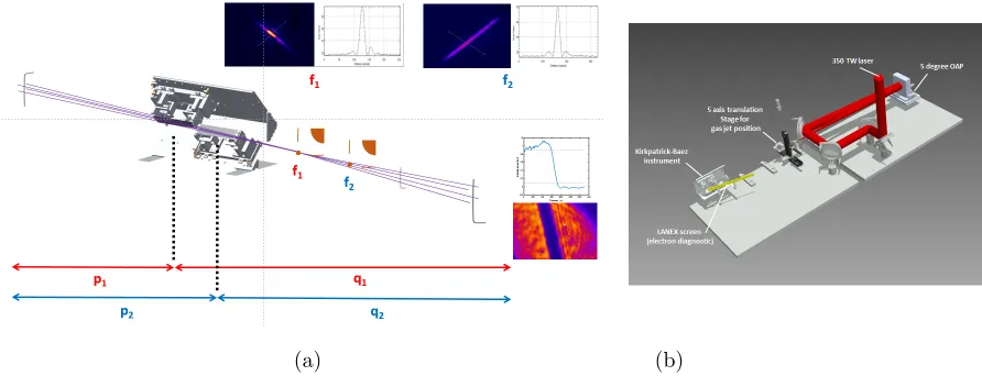
(a) (b)
Figure 1. (a) Experimental layout for the initial course alignment of the Kirkpatrick-Baez instrument. A 633 nm HeNe laser is co-aligned to the SCAPA 350 TW laser axis and CCD cameras are used to measure the focal spot for each KB mirror and the image. Two piezoelectric motors are used to provide a cantilever force to bend the KB mirrors; adjusting the radius of curvature and subsequently optimising the focal spot. (b) Layout of the SCAPA A2 beamline and positioning of the Kirkpatrick-Baez microscope.
2. KIRKPATRICK-BAEZ X-RAY OPTICS
A Kirkpatrick-Baez instrument uses two mirrors separated as shown in figure1to focus x-rays in each transverse dimension. The curved KB mirrors focus the x-rays with the radius of curvature controlled by two piezoelectric motors creating a cantilever force. x-ray reflective optics normally have an extremely fine tolerance of a few atomic spacings to ensure diffraction limited mirrors.10 KB mirrors require extensive metrological tools to
reduce fabrication errors and undesired strain in order to obtain micron scale resolution. This investigation reports on the development of compact (0.15 m) KB mirrors using polished silicon wafer substrates.
Two metrology tools, a Veeco roughness and 632 nm Zygo GPI xP/D interferometer were used to characterise the surface roughness and surface profile of Kirkpatrick-Baez mirrors respectively. Typically, the 40 nm sputtered Platinum coated mirrors show rising edges∼ 1.9µm (see figure 2), with peak-to valley distance 3.29 µm and RMS deviation of 0.75µm. A sampled region (2.4 mm by 1.4 mm) of one of the KB silicon wafer mirror was measured yielding a surface roughness measurement of 55.6 nm. Post-processing KB mirror metrological data into OASYS SHADOW OUI has enabled a more accurate prediction of the image resolution for the Kirkpatrick-Baez instrument.
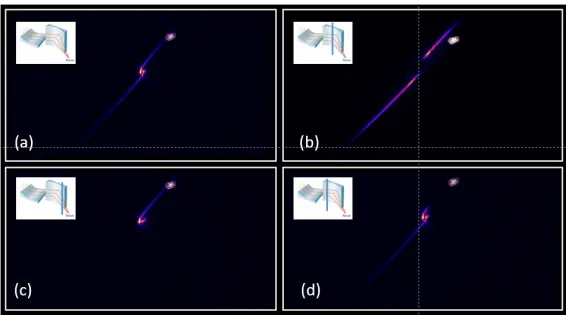
Figure3shows a KB focal spot with striated aberrations which may be caused due to a combination of strain induced mounting of the mirror and the rising edges of the mirror due to poor surface flatness. The source for this mirror defect was identified by blocking each end of the mirror with a card, thus removing each wing of the striated beam. To reduce the strain defects due to mirror-twist, micro-spheres were used along the mirror edge to ensure an equidistant layer of adhesive is applied.
3. EXPERIMENTAL SET-UP
A HeNe 633 nm laser with a beam expander is used for coarse alignment of the Kirkpatrick-Baez mirrors (see figure1). The Kirkpatrick-Baez mirrors can be used as a thin-lens imaging device,11where each mirror will have focal plane defined by equations1 and2,
[image:2.612.84.530.73.244.2]Figure 2. (a) Veeco metrology 55.64 nm surface roughness measurement. (b) Surface profile of the Kirkpatrick-Baez 40 nm Platinum coated silicon wafer mirrors, measured using the 632 nm Zygo GPI xP/D interferometer. The rising edges of the mirrors can be a source for aberrations in the x-ray beam. Metrological data was post-processed into OASYS SHADOW-OUI to improve simulation accuracy.
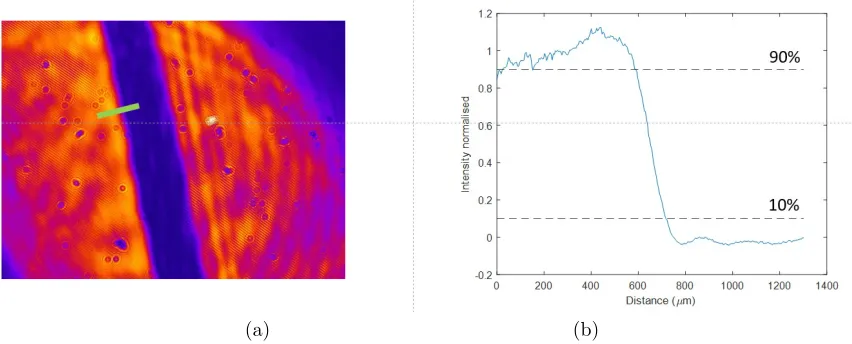
[image:3.612.164.447.433.593.2](a) (b)
Figure 4. (a) Knife-edge image formed of 1 mm thick obstruction aperture with associated line-out (b) The 10% - 90% knife edge resolution measurement is 138µm
where f is the focal length, p and q are defined as the distances from the source plane to KB (mirror centre) and KB (mirror centre) to image plane respectively. Piezoelectric motors on each end of the KB mirror provide a cantilever force to adjust the mirror radius of curvature and subsequently the focus, which is given by,
f = ROC
2 sinθ (3)
where ROC is the radius of curvature andθis the grazing angle. The knife-edge image (see figure4) has a 10% -90% resolution of 138µm. The theoretical Rayleigh resolution for 633 nm light is 103µm. For imaging of x-rays a scintillator imaging diagnostic has been designed using transparent 200µm thick high density and fast decay time Lutetium Cerium-doped (Lu1.8Y.2SiO5:Ce) scintillation screens (LYSO) to provide focal spot optimisation
in vacuum for x-rays.
4. SHADOW OUI RAYTRACING
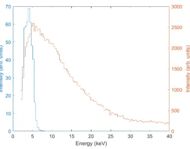
OASYS-SHADOW OUI code combines raytracing and wavefront propagation incorporating diffraction effects when the x-ray beam is clipped by apertures and optics. The adjustable KB can be used to focus a range of wavelengths including EUV x-rays at larger grazing angles (∼42 mrad) and hard x-rays at shallow grazing angles (∼15 mrad). The geometrical source used 100000 rays and the EUV and betatron x-ray source spectrum were post-processed into the code. Figure5shows the betatron energy spectrum from the source and is overlaid with the energy spectrum in the image plane after reflection from both KB mirrors. It is noted that in figure 5 at a grazing angle∼15 mrad the reflected spectrum is centered at∼4 keV. The peak intensity in the image plane of the KB is∼2% of the normalised source intensity. This reduction in intensity may arise due to the divergent nature of the source and small numerical aperture of the KB leading to fewer simulated rays in the image plane. The simulated x-ray beam profile was Gaussian and the polarisation and coherence were also included in the code. To assess the expected imaging performance a 10µm obstructive slit was simulated to evaluate the knife edge resolution. The object and image distance werep1= 0.925 m,p2= 1.075 m,q1= 5.075 m andq2= 4.925
m, producing a∼5 times magnified image of the laser plasma source.
The code imports the reflectively of the 40 nm Platinum coated silicon wafer mirror from the XOP database to determine the energy spectrum in the image plane (see figure5). The code was used to simulate the SCAPA beamline (see figure1) and predict the image resolution with post-processed metrological surface roughness and surface profile data. The simulated knife-edge (10% - 90%) resolution for a x-ray beam is∼3.8µm, where the theoretical Rayleigh resolution limit is∼1.69µm (see figure6).
[image:4.612.95.521.72.244.2]geometrical source is overlaid with the x-ray energy spectrum (blue) in the image plane after reflection from both KB mirrors. The code inputs Platinum reflectivity data from the XOP database and the grazing angle of the KB mirrors is set to∼15 mrad for hard x-rays.
(a) (b)
Figure 6. OASYS SHADOW-OUI raytracing and wave propagation code was used to simulate the plasma source image resolution using the Kirkpatrick-Baez microscope with magnification ∼ 5. Metrological surface profile data and the Platinum mirror reflectivity were incorporated into the code to provide simulated knife-edge (10% - 90%) resolution∼
3.8µm. This is larger than than the theoretical Rayleigh resolution limit which is∼1.69µm.
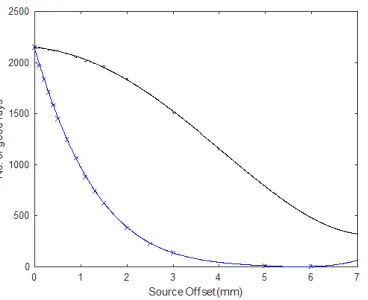
vertical plane. It can be seen that a 100µm offset in the vertical plane can reduce the number of rays by 10% in the image plane. High precision stepper-motors powering a translation stage have been incorporated into the new design of the Kirkpatrick-Baez system to reduce KB misalignment. The vertical plane alignment is more susceptible to misalignment due to the nominally small aperture size for KB mirrors at shallow grazing angles.
5. CONCLUSION
[image:5.612.216.409.77.229.2] [image:5.612.149.472.296.461.2]Figure 7. High precision alignment is required to maximise KB efficiency and performance. This figure shows the reduction in number of rays when the KB is offset in the horizontal (black) and vertical (blue) plane away from the centre laser axis.
Using the OASYS SHADOW-OUI code KB misalignment sensitivities were also estimated in the horizontal and vertical plane.
6. ACKNOWLEDGMENTS
This work was partially supported by EuPRAXIA (Grant No. 653782), ECs LASERLAB-EUROPE (Grant No. 654148), and the U.K. EPSRC grants No. EP/J018171/1,EP/J500094/1,EP/N028694/1,EP/K011952/1 and the AFRC (route to impact) grant.The authors also acknowledge the help from CLPU and University of Alberta in the design and fabrication of the microscope.
REFERENCES
[1] Wiggins, S., Boyd, M., Brunetti, E., Butler, N., Feehan, J., Gray, R., Hidding, B., Ireland, D., Li, W., Maitrallain, A., Manahan, G., McKenna, P., ODonnell, D., Scheck, M., Shahzad, M., Sheng, Z., Spesyvt-sev, R., Vieux, G., Watts, D., Welsh, G., Wilson, R., Zachariou, N., and Jaroszynski, D., “Application programmes at the scottish centre for the application of plasma-based accelerators (scapa),” in [SPIE Op-tics and Optoelectronics], 11036, 11036–28, SPIE (2019).
[2] Fuchs, M., Weingartner, R., Popp, A., Major, Z., Becker, S., Osterhoff, J., Cortrie, I., Zeitler, B., H¨orlein, R., Tsakiris, G. D., et al., “Laser-driven soft-x-ray undulator source,”Nature physics5(11), 826 (2009). [3] Pirozhkov, A. S., Kando, M., Esirkepov, T. Z., Gallegos, P., Ahmed, H., Ragozin, E. N., Faenov, A. Y.,
Pikuz, T. A., Kawachi, T., Sagisaka, A., Koga, J. K., Coury, M., Green, J., Foster, P., Brenner, C., Dromey, B., Symes, D. R., Mori, M., Kawase, K., Kameshima, T., Fukuda, Y., Chen, L., Daito, I., Ogura, K., Hayashi, Y., Kotaki, H., Kiriyama, H., Okada, H., Nishimori, N., Imazono, T., Kondo, K., Kimura, T., Tajima, T., Daido, H., Rajeev, P., McKenna, P., Borghesi, M., Neely, D., Kato, Y., and Bulanov, S. V., “Soft-x-ray harmonic comb from relativistic electron spikes,”Phys. Rev. Lett.108, 135004 (Mar 2012). [4] Pirozhkov, A. S., Kando, M., Esirkepov, T. Z., Gallegos, P., Ahmed, H., Ragozin, E. N., Faenov, A. Y.,
Pikuz, T. A., Kawachi, T., Sagisaka, A., et al., “High order harmonics from relativistic electron spikes,”
New Journal of Physics16(9), 093003 (2014).
[5] Schlenvoigt, H.-P., Haupt, K., Debus, A., Budde, F., J¨ackel, O., Pfotenhauer, S., Schwoerer, H., Rohwer, E., Gallacher, J., Brunetti, E., et al., “A compact synchrotron radiation source driven by a laser-plasma wakefield accelerator,”Nature Physics4(2), 130 (2008).
P., Umstadter, D., and Hulin, D., “Production of a kev x-ray beam from synchrotron radiation in relativistic laser-plasma interaction,”Phys. Rev. Lett.93, 135005 (Sep 2004).
[8] Reid, L. R., [Experimental investigation of the emission of high-brightness extreme ultraviolet radiation from laser-plasma interactions] (2018).
[9] Rebuffi, L. and del Rio, M. S., “Oasys (orange synchrotron suite): an open-source graphical environment for x-ray virtual experiments,” in [Advances in Computational Methods for X-Ray Optics IV],10388, 103880S, International Society for Optics and Photonics (2017).
[10] Mills, D., Padmore, H., and Lessner, E., “X-ray optics for bes light source facilities,” tech. rep., Brookhaven National Laboratory (BNL), Upton, NY (United States) (2013).