Having Tooth Tips
.
White Rose Research Online URL for this paper:
http://eprints.whiterose.ac.uk/85523/
Version: Accepted Version
Article:
Li, G.J., Zhu, Z.Q., Foster, M.P. et al. (2 more authors) (2015) Modular Permanent Magnet
Machines with Alternate Teeth Having Tooth Tips. IEEE Transactions on Industrial
Electronics. ISSN 0278-0046
https://doi.org/10.1109/TIE.2015.2427112
[email protected] https://eprints.whiterose.ac.uk/
Reuse
Unless indicated otherwise, fulltext items are protected by copyright with all rights reserved. The copyright exception in section 29 of the Copyright, Designs and Patents Act 1988 allows the making of a single copy solely for the purpose of non-commercial research or private study within the limits of fair dealing. The publisher or other rights-holder may allow further reproduction and re-use of this version - refer to the White Rose Research Online record for this item. Where records identify the publisher as the copyright holder, users can verify any specific terms of use on the publisher’s website.
Takedown
If you consider content in White Rose Research Online to be in breach of UK law, please notify us by
1
Abstract — This paper presents single layer modular permanent magnet machines with either wound or unwound teeth with tooth tips. The structures with wound teeth having tooth tips are suitable for modular machines with slot number higher than pole number to compensate for the drop in winding factor due to the flux gaps in alternate stator teeth, accordingly to maintain or even to increase their average torques. However, the structures with unwound teeth having tooth tips are suitable for modular machines with slot number lower than pole number to increase the winding factor and hence to further improve the machine performance. The phase back-EMF, on-load torque, iron and copper losses as well as efficiency have been calculated using finite element analysis for different slot/pole number combinations, and for different flux gap and tooth tip widths. It is found that by properly choosing the flux gap and tooth tip widths, both the on-load torque performance and the efficiency can be optimized for the investigated machines with different slot/pole number combinations. Experiments have been carried out to validate the finite element results.
Index Terms — Flux gap, iron losses, modular structure, permanent magnet, single layer, tooth tips, winding factor.
I. INTRODUCTION
UE to their high torque density and high efficiency, permanent magnet (PM) machines have been employed for industrial servo drives, domestic appliances, transportation such as more electrical aircraft, electrical vehicles and marine propulsion, as well as renewable energy such as tidal power and wind power, etc. [1]-[5]. Amongst the most widely used permanent magnet machines, the machines with modular stators carrying single layer concentrated windings are attracting increasing interests. This is particularly the case for safety critical applications such as more electrical aircraft, marine propulsion, offshore wind power, etc. [6]-[9], since these modular machines exhibit several advantages such as: (a) Simplicity for manufacturing particularly for the winding process [10]-[12], assembling and transportation of machine components when compared to their non-modular counterparts. This is especially the case for large volume hydroelectric generators or wind power generators. Meanwhile, the stator slot filling factor can be significantly increased using modular stators [13]-[14]. (b) High fault-tolerant capability can be achieved due to physical separation between segments [8]-[9], [15]-[17]. This can limit the fault propagation from one segment to another. Moreover, single layer concentrated windings are often used for modular machines leading to a low
Copyright (c) 2015 IEEE. Personal use of this material is permitted. However, permission to use this material for any other purposes must be obtained from the IEEE by sending a request to [email protected].
G. J. Li, Z. Q. Zhu, M. P. Foster, D. A. Stone and H. L. Zhan are with the Electrical machines & Drives (EMD) Group, University of Sheffield, Sheffield, UK ([email protected])
mutual/self-inductance ratio [18]. This can significantly mitigate the short-circuit current and limit fault interaction between phases and hence very suitable for safety critical applications [19]. (c) Simplicity of maintenance, the faulty modules can be replaced by healthy ones avoiding replacing the whole electrical machine. Moreover, it is also found that the radial and circumferential segment displacements have little effect on machine electromagnetic performance.
(a)
(b)
Fig. 1 Cross-sections of modular machines with alternate teeth having tooth tips. (a) wound teeth having tooth tips, more suitable for Ns > 2p, (b) unwound teeth having tooth tips, more suitable for Ns < 2p.
Although the modular structures inherently exhibit the above mentioned merits, they also have some undesirable disadvantages. Due to additional flux gaps (air-gap) in stator yoke or between stator teeth and stator yoke, the flux paths in stator core are dramatically modified [10]-[11]. This could lead to higher cogging torque and lower average torque due to the fact that the effective air-gap length has been increased. In
Modular Permanent Magnet Machines with Alternate Teeth
Having Tooth Tips
Guang-Jin Li, Member, IEEE, Zi-Qiang Zhu, Fellow, IEEE, Martin P. Foster, Dave A. Stone and Han-Lin Zhan
order to overcome these drawbacks, several new modular structures have been developed over recent years. In [8]-[9], flux-concentrating PM machines with modular stators and modular rotors for wind power generators have been proposed. Based on the comparison with their non-modular (continuous core) counterparts, it is found that the modular machines have lower active mass while higher efficiency for the full range of load. Similarly, by removing the PMs in alternate stator teeth of a linear switched flux permanent magnet (SFPM) machine, flux gaps are formed between stator segments and a modular SFPM machine with segmented stator is obtained accordingly [20]-[22]. It has been found that the modular machine with same volume of PMs can produce higher torque density compared to its non-modular counterpart. In [15]-[16], the modular structures have been obtained by directly inserting flux gaps into alternate stator teeth of interior permanent magnet (IPM) machines, the modular stator of which is similar to that shown in Fig. 1 while with all or no teeth having tooth tips. Both 12-slot/10-pole and 12-slot/14-pole modular IPM machines have been investigated. It is found that for a 12-slot/10-pole modular machine, both the winding factor and the on-load torque decrease due to flux gaps, while totally opposite phenomena have been observed for the 12-slot/14-pole modular machine. Moreover, as investigated in [23], the flux gaps can be used as water ducts to significantly improve the cooling efficiency.
Similar studies on modular machines to [15]-[16] have been carried out in [24]-[25]. All investigated machines have all or no stator teeth with tooth tips. Based on these studies, a generic rule has been established to describe the influence of flux gaps on machine performance. It has been clearly demonstrated that for machines having slot number, (Ns), lower than pole number, (2p), (Ns < 2p), the flux gaps increase the average torque. However, the flux gaps reduce the average torque of modular machines with Ns > 2p. It is worth noting that lower pole number means lower electrical frequency, and hence lower iron losses. With this perspective, it will be more desirable to utilize modular machines with Ns > 2p. Therefore, how to compensate their average torque drop due to flux gaps is one of the main topics in this paper. In order to do so, several novel modular structures have been proposed, as shown in Fig. 1. The specific features of the proposed topologies are that alternate stator teeth have tips, which is the main difference from the machines investigated in [15]-[16], [24]-[25] (having all or no teeth with tooth tips). This provides the possibility to boost the average torque of the modular machines with Ns > 2p while still maintaining the previously mentioned merits due to modular structure. Moreover, for modular machines with Ns < 2p, in addition to the contribution of flux gaps, their average torque can be further increased by properly choosing the tooth tip width. Apart from the phase back-EMF and average torque, another main focus of this paper is to comprehensively investigate the influences of flux gap and tooth tip widths on power losses and efficiency of modular machines, as will be detailed in the following sections. Due to the improvement in fault tolerant capability and electromagnetic performance, the proposed modular machines can be used for safety-critical applications such as “more electrical” aircraft (small sized machines), or wind power generators (large sized machines).
II. EMF AND TORQUE ANALYSIS OF PROPOSED MODULAR
MACHINES
A. Topologies
The proposed topologies with alternate stator teeth having tooth tips, as shown in Fig. 1, have flux gaps between stator segments and the width of flux gaps is 0 and may be variable. When the flux gap width changes, to maintain a constant magnetic saturation level in the stator iron core, the total active iron sections in the stator teeth, either with or without flux gaps, are the same (2t0) and unchanged. As for the flux gap width, the tooth tip circumferential width ( 0) can vary as well. As can be seen in Fig. 1, the windings of all the modular machines to be investigated are single layer concentrated ones, which are wound on the middle teeth without flux gaps to form independent stator segments. The single layer concentrated winding structure is for increasing the self-inductances while decreasing the mutual inductances and hence improving the fault-tolerant capability. In [26], it is found that the self-inductance of a single layer SFPM machine is more than doubled compared to its double layer counterpart while with much lower mutual inductances. When compared to machines with distributed windings, the single layer concentrated winding as shown in Fig. 1 is also more desirable and will also have predictably lower mutual inductances.
(a)
[image:3.612.315.565.344.623.2](b)
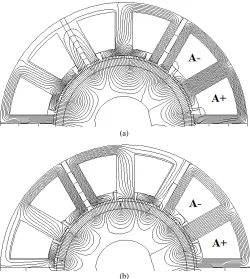
Fig. 2 Open-circuit flux line distributions. The flux gap width is 3 mm and the rotor position is where the phase A has its peak flux. (a) 12-slot/10-pole with wound teeth having tips, (b) 12-slot/14-pole with unwound teeth having tips.
However, for the machines with Ns < 2p, the tooth tips should be on the unwound teeth, as shown in Fig. 1 (b). This can further reduce the slot pitch and further increase the winding factor (see Appendix). As a result, the average torque can be further improved as well.
B. Phase Back-EMF
The open-circuit flux line distribution for modular machines with alternate teeth having tooth tips are obtained using 2-D finite element (FE) software package, Opera, and the used machine dimensions are the same as given in TABLE I.
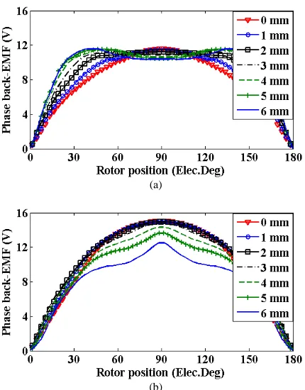
The flux gaps and tooth tips will influence the winding factor (see Appendix), and hence the phase back-EMFs and their spectra, as shown in Fig. 3 and Fig. 4, respectively. By way of example, 12-slot/10-pole and 14-pole modular machines have been chosen for comparison. The flux gap width is constant and set to 3 mm while the tooth tip width ranges from 0 mm to 6 mm.
(a)
[image:4.612.328.542.50.320.2](b)
Fig. 3 Phase back-EMFs vs tooth tip width increase of modular machines. The flux gap width is 3 mm. (a) 12-slot/10-pole with wound teeth having tips, (b) 12-slot/14-pole with unwound teeth having tips.
It is found that,
For the modular machine with 12-slot/10-pole, the fundamental of phase back-EMF increases with tooth tip width increase until 4 mm then decreases slightly. This is mainly due to the fact that the pitch factor will increase to unity and begin to decline afterwards;
For the modular machine with 12-slot/14-pole, the fundamental of phase back-EMF increases with tooth tip width increase to 2 mm then decreases thereafter. This is mainly due to the fact that the pitch factor has already increased due to the flux gaps. Thus a slight increase in tooth tip width can make its pitch factor reach unity. As a result, if the tooth tip width continues to increase, the pitch factor and hence the winding factor will decrease.
(a)
(b)
Fig. 4 Spectra of phase back-EMFs vs tooth tip width increase of modular machines. The flux gap width is 3 mm. (a) 12-slot/10-pole with wound teeth having tips, (b) 12-slot/14-pole with unwound teeth having tips.
C. Electromagnetic Torques
[image:4.612.63.278.255.530.2](a)
(b)
Fig. 5 Average torque and torque ripple (peak-to-peak) vs tooth tip width increase and flux gap width of 12-slot/10-pole and 12-slot/14-pole modular machines with alternate teeth having tooth tips. FG stands for flux gap width. (a) average torque, (b) torque ripple.
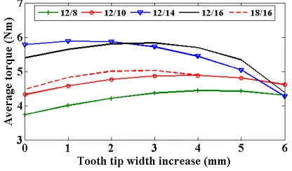
[image:5.612.61.276.47.323.2]To generalize the proposed theory, the average torques vs tooth tip width increase for modular machines with different slot/pole number combinations have been calculated as shown in Fig. 6.
Fig. 6 Average torque vs tooth tip width increase for modular machines with different slot/pole number combinations. The flux gap width for 12/8, 12/10, 12/14 and 12/16 is 3 mm, while for 18/16 is 1 mm due to higher number of slot.
III. POWER LOSS ANALYSIS OF PROPOSED MODULAR
MACHINES
A. Open-Circuit and On-Load Iron Losses
Due to the flux gaps and the tooth tips, the air-gap permeance and the flux path in stator iron core will be modified. Therefore, the flux gaps and tooth tips have influences not only on winding factor and phase back-EMF but also on the air-gap flux densities either due to PMs or due to armature field and hence an influence on machine core losses. For both open-circuit and on-load conditions, the hysteresis and eddy current losses in stator and rotor iron cores can be calculated by using the same method given in [27]. Similarly,
the total PM eddy current losses can be calculated by summing up the eddy current losses in all mesh elements of PMs of the 2D FE model.
(a)
(b)
(c)
Fig. 7 Open-circuit and on-load iron losses vs flux gap width and tooth tip width increase of modular 12-slot/14-pole machine with unwound teeth having tips. (a) stator iron losses, (b) rotor PM eddy current losses, (c) total iron losses.
At rated rotor speed, the open-circuit and on-load iron losses as well as PM eddy current losses of the investigated modular machines have been calculated for different flux gap and tooth tip width increases. It has been found that for both the investigated modular machines, the relationships between core losses and flux gap width or tooth tip width increase are similar. Thus, only the results of the 12-slot/14-pole modular machine with unwound teeth having tooth tips have been shown in Fig. 7. The laminated rotor core iron losses are negligible when compared to stator iron losses and PM eddy current losses, thus they are not shown here. It can be seen that
[image:5.612.325.550.87.506.2] [image:5.612.67.275.427.549.2] For the PMs, the open-circuit and on-load eddy current losses decrease slightly with the increase in flux gap width, while they decrease significantly with the increase in tooth tip width;
For total losses, under both open-circuit and on-load conditions, their variations are similar to that of stator iron losses because the stator iron losses dominant compared to rotor core iron losses + PM eddy current losses.
(a)
[image:6.612.321.542.48.621.2](b)
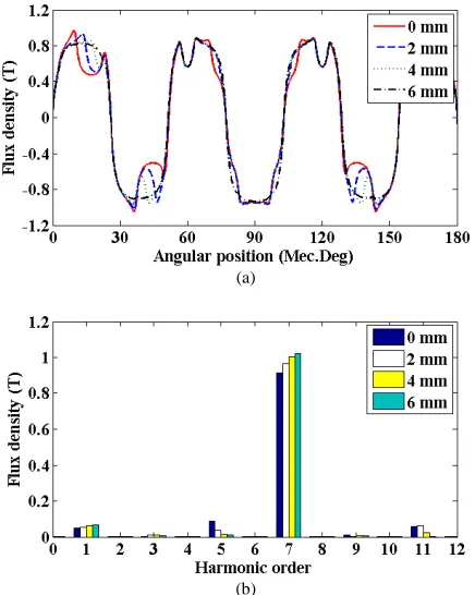
Fig. 8 Radial air-gap flux densities due to PMs and their spectra of the modular 12-slot/14-pole machine with unwound teeth having tooth tips. The flux gap width is 3 mm. (a) Air-gap flux density due to PMs, (b) Spectra.
(a)
(b)
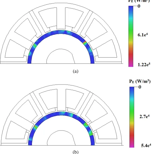
Fig. 9 Open-circuit eddy current loss density distribution within PMs of the 12-slot/14-pole modular machine with unwound teeth having tooth tips. The flux gap width is 3 mm. (a) tooth tip width increase is 1 mm, (b) tooth tip width increase is 5 mm.
(a)
(b)
(c)
[image:6.612.60.278.143.416.2](d)
Fig. 10 Radial air-gap flux density due to armature field and on-load air-gap flux density of the 12-slot/14-pole modular machine with unwound teeth having tooth tips. Flux gap width is 3 mm. (a) Air-gap flux density due to armature field, (b) spectra, (c) on-load air-gap flux denisty, (d) spectra.
[image:6.612.49.300.462.696.2]different tooth tips and their spectra are shown in Fig. 8, in which the flux gap width is 3mm. For a machine with 12-slot/14-pole, the 7th order harmonic of air-gap flux density due to PMs will interact with the 7th order harmonic of stator MMF to generate the output torque. Besides, there is no relative movement between the 7th order harmonic of air-gap flux density due to PMs and the PMs themselves. Therefore, it will not generate PM eddy current losses. However, since the 7th order harmonic of air-gap flux density due to PMs cross through the stator iron core and hence will cause the stator core iron losses. Due to the fact that both the volume of stator iron core and the 7th order harmonic of air-gap flux density due to PMs increase with the increase in tooth tip width [see Fig. 8 (b)], therefore, the observed increase in stator core iron losses in Fig. 7 can then be explained. The other order harmonics (1st, 3rd, 5th, 9th, 11th, etc.) in air-gap flux density due to PMs mainly generate PM eddy current losses. As can be seen in Fig. 8 (b), the harmonics (the 1st harmonic is almost constant and the 3rd and 9th harmonics are negligible) decrease with the increase in tooth tip width. This is why the PM eddy current losses significantly decrease as shown in Fig. 9, in which the eddy current loss density decreases with the increase in tooth tip width.
(a)
(b)
Fig. 11 On-load eddy current loss density distribution within PMs of the 12-slot/14-pole modular machine with unwound teeth having tooth tips. The flux gap width is 3 mm. (a) tooth tip width increase is 1 mm, (b) tooth tip width increase is 5 mm.
In order to analyze the influence of tooth tips on the on-load losses, the air-gap radial flux density only due to armature field and the on-load air-gap flux density have been calculated for different tooth tip width increases as shown in Fig. 10, in which the flux gap width is 3mm. The on-load losses observed in Fig. 7 is only slightly higher than the open-circuit losses since the air-gap flux density due to armature field is much lower than that due to PMs when the PMs are replaced by airspace in the finite element models. The lower order harmonics (1st and 5th) decrease with the increase in tooth tip width, thus, although higher order harmonics (11th) slightly increase, the PM eddy
current loss due to armature field still decreases, so does the on-load PM eddy current losses as shown in Fig. 11 (the maximum eddy current density in PMs decreases with the increase in tooth tip width).
B. Copper Loss and Efficiency
The copper loss can be calculated by using the simple equation described by [25]
(1)
where (Ωm) is the resistivity of copper wire, Nc is the number of conductor in one slot, Lef is the stack length, S (m
2
) is the area of one slot, kb is the filling factor and IRMS (A) is the rated RMS phase current.
In equation (1), only is variable which changes with the flux gap width while it is independent of tooth tip width increase. This is mainly due to the fact that the tooth tip height is constant and there is no winding in the slot opening. Therefore, the change in tooth tip width increase, and hence slot opening, will not lead to change in slot area. The copper loss has been calculated, as shown in Fig. 8. It can be found that the copper loss increases with flux gap width, while it is constant for all tooth tip width increases. It is also worth noting that for 12-slot/10-pole or 12-slot/14-pole machine, the copper losses are the same as the phase current is the rated RMS current.
It is worth noting that (1) only takes into account the DC copper loss. As investigated in [28], the alternate stator teeth having tips will lead to higher slot leakage and hence additional AC copper losses. However, this is out of the scope of this paper, and the AC copper losses are assumed small and negligible.
Fig. 12 Copper loss vs tooth tip width increase and flux gap width for 12-slot/10-pole and 14-pole modular SPM machines. The current is rated current.
[image:7.612.52.295.315.561.2] [image:7.612.325.543.427.542.2]that by properly choosing the tooth tip and flux gap widths, the efficiencies of both the 12-slot/10-pole and 14-pole modular SPM machines can be optimized.
Fig. 13 Efficiency vs tooth tip and flux gap widths for 12-slot/10-pole and 14-pole modular SPM machine under rated condition. FG stands for flux gap width.
(a) (b)
Fig. 14 Stator segments with alternate teeth having tooth tips. (a) with wound teeth having tooth tips (12-slot/10-pole type), (b) with unwound teeth having tooth tips (12-slot/14-pole type).
(a) (b)
[image:8.612.62.277.86.203.2](c) (d)
Fig. 15 Prototypes of modular machines. (a) rotor with 10 poles, (b) rotors with 14 poles, (c) completed stator with wound teeth having tooth tips (12-slot/10-pole type), (d) completed stator with unwound teeth having tooth tips (12-slot/14-pole type).
IV. EXPERIMENTAL VALIDATION
A. Prototypes of Modular Machines
In order to validate the foregoing predictions and conclusions, two optimized prototype machines based on the previous analysis have been built for experiments as shown in Fig. 14 and Fig. 15, and their parameters are given in TABLE I. The flux gap widths for all prototypes are 3mm. However, for 12-slot/10-pole machine, its tooth tip width increase is 4mm
while for 12-slot/14-pole machine, its tooth tip width increase is 2mm.
TABLE I MACHINE PARAMETERS
Phase voltage (V) 36 Stator yoke height (mm) 3.7 Rated torque (Nm) 5.5 Stack length (mm) 50 Rated current (ARMS) 7.34 Air-gap length (mm) 1 Rated speed (rpm) 400 Rotor outer radius (mm) 27.5 Slot number 12 Magnet thickness (mm) 3 Pole number 10/14 Magnet remanence (T) 1.2 Stator outer radius (mm) 50 Number of turns per phase 132 Stator inner radius (mm) 28.5 Filling factor kb 0.37
B. Phase Back-EMF
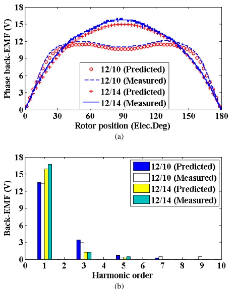
At rated speed, the phase back-EMFs of phase A for 12-slot/10-pole and 12-slot/14-pole modular machines have been calculated and compared with their relevant predicted results as shown in Fig. 16.
(a)
[image:8.612.321.549.244.531.2](b)
Fig. 16 Predicted and measured phase back-EMFs of modular machines with alternate teeth with tooth tips. (a) phase back-EMFs, (b) spectra.
C. Static Electromagnetic Torques
[image:8.612.49.297.358.585.2]where I is a DC current which can be varied. The rotor position is fixed to the position where the maximum average torque can be achieved. Then, the static torque versus phase RMS current is measured and compared with the predicted results in Fig. 18. The overall agreement between the predicted and measured results in terms of phase back-EMF, cogging torque and static torque proves the accuracy of the theory established in this paper.
[image:9.612.49.283.145.436.2]Fig. 17 Test rig for static torque measurements.
Fig. 18 Static torque vs phase RMS current of modular 3-phase machine with alternate teeth with tooth tips.
D. Torque and Efficiency Speed Curves
The torque speed curves have been obtained by dynamic tests according to the method in [30] and the predicted and measured results are compared in Fig. 19. The DC link voltage for all tests is 40 V and the phase maximum peak current is 3.67A, which is limited by the load torque produced by the DC machine. The torques for different speeds are measured by using a torque sensor. The measured torques for both the 12-slot/10-pole and 12-slot/14-pole machines are ~9% lower than the predicted torques, mainly due to the end effect which is neglected in the 2D FE prediction. But the overall agreement is good while the trend is the same.
Fig. 19 2D FE Predicted and measured torque speed curves of modular
machines with alternate teeth with tooth tips.
[image:9.612.67.273.615.727.2]The measured efficiencies for both the 12-slot/10-pole and 12-slot/14-pole modular machines are shown in Fig. 20. Compared to the simulated results shown in Fig. 13, the measured efficiencies are lower. This is mainly due to the fact that the mechanical losses and the additional winding AC losses have not been taken into account in the simulation.
Fig. 20 Measured efficiencies for modular machines with alternate teeth having tooth tips.
V. CONCLUSIONS
In this paper, the modular machines with alternate teeth having tooth tips have been proposed to improve machine performance. The results such as winding factor (see Appendix), phase back-EMF, average torque and torque ripple have shown that
(a).For machines with Ns > 2p, the flux gaps reduce the winding factor but by using tooth tips on wound teeth, the drop in winding factor can be compensated, therefore, the average torque can be maintained or even increased. However, for machines with Ns < 2p, the winding factor of which can be increased by flux gaps and be further increased by tooth tip on unwound teeth, so does the average torque;
(b).For the investigated modular machines, the torque ripples can be minimized by changing the tooth tip and flux gap widths;
The FE predictions and conclusions have been verified by experiments. In addition, FE analyses show that for both investigated machines, the open-circuit and on-load stator iron losses increase with the increase in flux gap and tooth tip widths (except for very large tooth tip width) while opposite phenomena have been observed for open-circuit and on-load PM eddy current losses. The rotor core iron losses are negligible and the total open-circuit and on-load iron losses variations are similar to that of stator iron losses. It can be concluded that by properly choosing the flux gap and tooth tip widths, both the on-load torques and efficiencies can be optimized for different slot/pole number combinations.
VI. APPENDIX -CALCULATION OF WINDING FACTOR FOR MODULAR MACHINES WITH ALTERNATE TEETH HAVING TOOTH
TIPS
Therefore, the stator slot numbers must be equal to multiples of 12. As a result, all non-modular machines have the same maximum distribution factors, i.e. 1 and the same maximum winding factors, i.e. 0.966. Moreover, all the machines having the maximum winding factor are either multiples of 12-slot/10-pole or multiples of 12-slot/14-pole ones [24]. Therefore, only the 12-slot/10-pole and 12-slot/14-pole machines will be selected as baseline to investigate the influences of flux gap and tooth tip widths on machine performance.
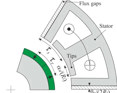
Fig. 21 Illustration for pitch factor calcualtion of modular machines with flux gaps and with wound teeth having tooth tips (Ns > 2p).
However, for modular machines with alternate teeth having tooth tips as shown in Fig. 1 and Fig. 21, due to the flux gaps and tooth tips, the pitch factors have been modified because of the variation of slot pitches. In order to take the flux gaps and tooth tips into account for calculating the slot pitch, the expression of which should be modified by
where Ri is the stator inner radius as shown in Fig. 1 and is the slot pitch without flux gaps.
Therefore, the pitch factor can be calculated by sin
where is the pole pitch.
The idea here is as follows. For machines with Ns > 2p as shown in Fig. 1, the flux gaps squeeze the slot pitch and hence reduce the pitch factor and winding factor. Therefore the tooth tips should be on the wound teeth to enlarge the slot pitch, as shown in Fig. 1 (a), and the sign before 0is “+”. However, for machines with Ns < 2p, in order to further increase the pitch factor, the tooth tips should be on the unwound teeth, as shown in Fig. 1 (b), and the sign before 0is “-”.
Using previous equation for modified pitch factor together with a maximum distribution factor of 1, the winding factors against flux gap width and tooth tip width increase have been calculated as shown in Fig. 22. It can be seen that for 12-slot/10-pole modular machine with wound teeth having tips, the winding factor of which decreases with the increase in flux gap width, while this decrease can be compensated by increasing the tooth tip width to a certain value, and eventually a winding factor of unity can be obtained. On the other hand, for 12-slot/14-pole modular machine with unwound teeth having tips, the winding factor of which first increases with the increase in the flux gap width then decreases thereafter. Besides, at low flux gap width, the winding factor can be further increased by increasing the tooth tip width. However, at
high flux gap width, since the slot pitch is already lower than the pole pitch, any extra increase in the tooth tip width will lead to a significant decrease in the winding factor.
(a)
(b)
Fig. 22 Winding factor vs flux gap width and tooth tip width increase. (a) 12-slot/10-pole with wound teeth having tips, (b) 12-slot/14-pole with unwound teeth having tips.
REFERENCES
[1] I. Boldea, L.N. Tutelea, L. Parsa, and D. Dorrell, "Automotive electric propulsion systems with reduced or no permanent magnets: an overview," IEEE Trans. Ind. Electron., vol. 61, no. 10, pp. 5696-5711, Oct. 2014.
[2] P. Sergeant and A.P.M. Van den Bossche, "Influence of the amount of permanent-magnet material in fractional-slot permanent-magnet synchronous machines," IEEE Trans. Ind. Electron., vol. 61, no. 9, pp. 4979-4989, Sept. 2014.
[3] P. Arumugam, T. Hamiti, C. Brunson, and C. Gerada, "Analysis of vertical strip wound fault-tolerant permanent magnet synchronous machines," IEEE Trans. Ind. Electron., vol. 61, no. 3, pp. 1158-1168, Mar. 2014.
[4] X. Y. Huang, A. Goodman, C. Gerada, Y. T. Fang, and Q. f. Lu, "Design of a five-phase brushless dc motor for a safety critical aerospace application," IEEE Trans. Ind. Electron., vol. 59, no. 9, pp. 3532-3541, Sept. 2012.
[5] J. H. J. Potgieter and M. J. Kamper, "Torque and voltage quality in design optimization of low-cost non-overlap single layer winding permanent magnet wind generator," IEEE Trans. Ind. Electron., vol. 59, no. 5, pp. 2147-2156, May 2012.
[6] M. Villani, M. Tursini, G. Fabri, and L. Castellini, "High reliability permanent magnet brushless motor drive for aircraft application," IEEE Trans. Ind. Electron., vol. 59, no. 5, pp. 2073-2081, May 2012. [7] N. Bianchi and M. Dai Pre, "Use of the star of slots in designing
fractional-slot single-layer synchronous motors," IEE Proc. Elec. Power Appl., vol. 153, no. 3, pp. 459- 466, May 2006.
[8] E. Spooner and C. Williamson, "Electromagnetic machine with at least one pair concentric rings having modulized magnets and yokes," US patent 5844341, Dec. 1, 1998.
[9] E. Spooner, A. C. Williamson, and G. Catto, "Modular design of permanent-magnet generators for wind turbines," IEE Proceedings Elec. Power Appl., vol. 143, no. 5, pp. 388-395, Sep. 1996.
[image:10.612.66.268.165.326.2]Influence of stator teeth and back-iron," in Proc. ICEMS 2006, Nagasaki, Japan, 2006, pp. 1-4.
[11] Z. Q. Zhu, Z. Azar, and G. Ombach, "Influence of additional air gaps between stator segments on cogging torque of permanent-magnet machines having modular stators," IEEE Trans. Mag., vol. 48, no. 6, pp. 2049-2055, Jun. 2012.
[12] B. Bickel, J. Franke, and T. Albrecht, "Manufacturing cell for winding and assembling a segmented stator of PM-synchronous machines for hybrid vehicles," in 2nd International Electric Drives Production Conference (EDPC), 15-18 Oct. 2012, pp. 1-5.
[13] A. M. EL-Refaie, "Fractional-slot concentrated-windings synchronous permanent magnet machines: opportunities and challenges," IEEE Trans. Ind. Electron., vol. 57, no. 1, pp. 107-121, Jan. 2010. [14] H. Akita, Y. Nakahara, N. Miyake, and T. Oikawa, "New core structure
and manufacturing method for high efficiency of permanent magnet motors," in 38th IAS Annual Meeting. Conference Record of the Industry Applications Conference, Oct. 2003, pp. 367- 372.
[15] G. Dajaku, "Elektrische Maschine," patent DE 102012103677.2, May 04, 2012.
[16] G. Dajaku and D. Gerling, "Low costs and high-efficiency electric machines," in 2nd International Electric Drives Production Conference (EDPC), 15-18 Oct. 2012, pp. 1-7.
[17] L. Szabo and M. Ruba, "Segmental stator switched reluctance machine for safety-critical applications," IEEE Trans. Ind. Appl., vol. 48, no. 6, pp. 2223-2229, Nov.-Dec. 2012.
[18] N. Bianchi, S. Bolognani, and M. D. Pŕ, "Impact of stator winding of a five-phase permanent-magnet motor on postfault operations," IEEE Trans. Ind. Electron., vol. 55, no. 5, pp. 1978-1987, May 2008. [19] W. P. Cao, B. C. Mecrow, G. J. Atkinson, J. W. Bennett, and D. J.
Atkinson, "Overview of electric motor technologies used for more electric aircraft (MEA)," IEEE Trans. Ind. Electron., vol. 59, no. 9, pp. 3523-3531, Sept. 2012.
[20] E. Hoang, A. Ben Ahmed, and J. Lucidarme, "Switching flux permanent magnet polyphase synchronous machines," in European Conference on Power Electronics and Applications (EPE), 1997, pp. 903-908.
[21] M. J. Jin, C. F. Wang, J. X. Shen, and B. Xia, "A modular permanent-magnet flux-switching linear machine with fault-tolerant capability," IEEE Trans. Mag., vol. 45, no. 8, pp. 3179-3186, Aug. 2009.
[22] R. L. Owen, Z. Q. Zhu, A. S. Thomas, G. W. Jewell, and D. Howe, "Alternate poles wound flux-switching permanent-magnet brushless ac machines," IEEE Trans. Ind. Appl., vol. 46, no. 2, pp. 790-797, Mar.-Apr. 2010.
[23] A. Nollau and D. Gerling, "Novel cooling methods using flux-barriers," in 2014 International Conference on Electrical Machines (ICEM), Berlin, Germany, 2-5 Sept. 2014, pp. 1328-1333. [24] G. J. Li, Z. Q. Zhu, M. Foster, and D. Stone, "Comparative studies of
modular and unequal tooth pm machines either with or without tooth tips," IEEE Trans. Mag., vol. 50, no. 7, pp. 1-10, Jul. 2014.
[25] G. J. Li, Z. Q. Zhu, W. Q. Chu, M. P. Foster, and D. A. Stone, "Influence of flux gaps on electromagnetic performance of novel modular pm machines," IEEE Trans. Energy Convers., vol. 29, no. 3, pp. 716-726, Sept. 2014.
[26] G. J. Li, Ojeda X., Hlioui S., Hoang E., and and Gabsi M., "Double and single layers flux-switching permanent magnet motors: Fault tolerant model for critical applications," in ICEMS 2011, Beijing, China, 20-23 August 2011.
[27] G. Li, J. Ojeda, E. Hoang, M. Gabsi, and M. Lecrivain, "Thermal – electromagnetic analysis for driving cycles of embedded flux-switching permanent-magnet motors," IEEE Trans. Veh. Technol., vol. 61, no. 1, pp. 140-151, Jan. 2012.
[28] G.J. Atkinson et al., "The analysis of losses in high-power fault-tolerant machines for aerospace applications," IEEE Trans. Ind. Appl., vol. 42, no. 5, pp. 1162-1170, Sept.-Oct. 2006.
[29] Z. Q. Zhu, "A simple method for measuring cogging torque in permanent magnet machines," in IEEE Power & Energy Society General Meeting, 26-30 Jul. 2009, pp. 1-4.
[30] T. S. Kwon and S. K. Sul, "Novel Antiwindup of a Current Regulator of a surface-mounted permanent-magnet motor for flux-weakening control," IEEE Trans. Ind. Appl., vol. 42, no. 5, pp. 1293-1300, Sept.-Oct. 2006.
G. J. Li received his BEng, MSc and PhD degrees in
electrical and electronic engineering from the Wuhan University, China, in 2007, University of Paris XI, France, in 2008, and the Ecole Normale Supérieure (ENS) de Cachan, Paris, France, in 2011, respectively. He joined the University of Sheffield in June 2012 as a post-doctoral research associate at EMD Group. Since September 2013, he took up a Lectureship in Electrical Engineering within the EMD Group at the University of Sheffield. His main research interests include the design, fault analysis and thermal management of electrical machines for renewable energy, automotive, more electrical aircraft, etc.
Z. Q. Zhu (M’90–SM’00–F’09) received the B.Eng. and M.Sc. degrees in electrical and electronic engineering from Zhejiang University, Hangzhou, China, in 1982 and 1984, respectively, and the Ph.D. degree in electrical and electronic engineering from the University of Sheffield, Sheffield, U.K., in 1991. Since 1988, he has been with the University of Sheffield, where he is currently a Professor of electrical machines and control systems, the Head of the Electrical Machines and Drives Research Group, and the Academic Director of the Sheffield Siemens Wind Power Research Centre. His current major research interests include the design and control of permanent-magnet brushless machines and drives for applications ranging from automotive to renewable energy.
M. P. Foster received the B.Eng. degree in electronic and
electrical engineering, the M.Sc.(Eng.) degree in control systems, and the Ph.D. degree from the University of Sheffield, Sheffield, U.K., in 1998, 2000, and 2003,
respectively. His Ph.D. thesis focused on “Analysis and
Design of High-order Resonant Power Converters.” Since 2003, he has been a member of the academic staff in the Department of Electronic and Electrical Engineering, University of Sheffield, where he is involved in power electronic systems. His current research interests include the modeling and control of switching power converters, resonant power supplies, multilevel converters, battery management, piezoelectric transformers, power electronic packaging, and autonomous aerospace vehicles.
D. A. Stone received the B.Eng. degree in electronic
engineering from the University of Sheffield, Sheffield, U.K., in 1984 and the Ph.D. degree from Liverpool University, Liverpool, U.K., in 1989. He then returned to the University of Sheffield as a member of academic staff specializing in power electronics and machine drive systems. His current research interests are in hybrid-electric vehicles, battery charging, EMC and novel lamp ballasts for low pressure fluorescent lamps.
H. L. Zhan received the B.Eng. and the M.Sc. degrees in
Electrical Engineering from Harbin Institute of Technology, Harbin, China, in 2012 and 2014, respectively. He is currently working toward Ph.D. degree with the Department of Electronics and Electrical Engineering, the University of Sheffield, Sheffield, U.K.