City, University of London Institutional Repository
Citation
:
Li, S., Fairbank, M., Wunsch, D. C. and Alonso, E. (2012). Vector Control of a
Grid-Connected Rectifier/Inverter Using an Artificial Neural Network. Paper presented at the
IEEE International Joint Conference on Neural Networks (IEEE IJCNN 2012), 1783-1789,
10-15-2012, Brisbane, Australia.
This is the accepted version of the paper.
This version of the publication may differ from the final published
version.
Permanent repository link:
http://openaccess.city.ac.uk/5206/
Link to published version
:
http://dx.doi.org/10.1109/IJCNN.2012.6252614
Copyright and reuse:
City Research Online aims to make research
outputs of City, University of London available to a wider audience.
Copyright and Moral Rights remain with the author(s) and/or copyright
holders. URLs from City Research Online may be freely distributed and
linked to.
City Research Online:
http://openaccess.city.ac.uk/
[email protected]
Abstract -- Three-phase grid-connected converters are widely used in renewable and electric power system applications. Traditionally, grid-connected converters are controlled with standard decoupled d-q vector control mechanisms. However, recent studies indicate that such mechanisms show limitations. This paper investigates how to mitigate such problems using a neural network to control a grid-connected rectifier/inverter. The neural network implements a dynamic programming (DP) algorithm and is trained using backpropagation through time. The performance of the DP-based neural controller is studied for typical vector control conditions and compared with conventional vector control methods. The paper also investigates how varying grid and power converter system parameters may affect the performance and stability of the neural control system. Future research issues regarding the control of grid-connected converters using DP-based neural networks are analyzed.
Index Terms – grid-connected rectifier/inverter, decoupled vector control, renewable energy conversion systems, neural controller, dynamic programming, backpropagation through time
I. INTRODUCTION
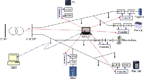
N renewable and electric power system applications, a three-phase grid-connected dc/ac voltage-source PWM converter is usually employed to interface between the dc and ac systems. Typical converter configurations containing the grid-connected converter (GCC) include: 1) a dc/dc/ac converter for solar, battery and fuel cell applications [1, 2], 2) a dc/ac converter for STATCOM applications [3, 4], and 3) an ac/dc/ac converter for wind power and HVDC applications [4-8]. Figure 1 demonstrates the grid-connected dc/ac converter used in a microgrid to connect distributed energy resources. Conventionally, this type of converters is controlled using the standard decoupled d-q vector control approach [5-8].
Notwithstanding its merits, recent studies indicate that the conventional vector control strategy is inherently limited [9, 10], particularly when facing uncertainties [11]. For instance,
This work was supported in part by the U.S. National Science Foundation under Grant EECS 1059265/1102159 and Missouri S&T Intelligent Systems Center.
Shuhui Li is with the Department of Electrical & Computer Engineering, The University of Alabama, Tuscaloosa, AL 35487, USA (email: [email protected]). Michael Fairbank and Eduardo Alonso are with the School of Informatics, City University London, UK (email: [email protected], [email protected]).
Donald C. Wunsch, the Mary K. Finley Missouri Endowment professor, is with the Department of Electrical & Computer Engineering, Missouri University of Science and Technology, Rolla, MO 65409-0040, USA (email: [email protected]).
[5, 12, 13] show that wind farms periodically experience a high degree of imbalance and harmonic distortions, which have resulted in numerous trips. Additionally, in [3], it is noted that tuning PI parameters for the standard control method in a STATCOM application is difficult.
[image:2.612.316.564.349.485.2]To overcome such deficiencies, an adaptive control approach was proposed recently that employs a direct-current control (DCC) strategy [14, 15]. However, a major challenge of the direct-current-based vector control mechanism is that no well-established systematical approach to tuning the PI controller gains exists, so that optimal DCC is extremely hard to obtain. This difficulty motivates the development of neural-network-based optimal control techniques for the vector control application, as presented in this paper.
Fig. 1. Application of grid-connected rectifier/inverter in a microgrid
In recent years, significant research has been conducted in the area of dynamic programming (DP) for optimal control of nonlinear systems [16-20]. Classical DP methods discretize the state space and directly compare the costs associated with all feasible trajectories that satisfy the principle of optimality, guaranteeing the solution of the optimal control problem [21]. Adaptive critic designs constitute a class of approximate dynamic programming (ADP) methods that use incremental optimization combined with parametric structures that approximate the optimal cost and the control [22, 23]. Both classical DP and ADP methods have been used to train neural networks for a large number of nonlinear control applications, such as steering and controlling the speed of a two-axle vehicle [24], intercepting an agile missile [25], performing auto landing and control of an aircraft [26-28], and controlling a turbogenerator [29]. However, no research has been conducted regarding the vector control of grid-connected power electronic converters using DP or ADP-based neural networks.
Vector Control of a Grid-Connected Rectifier/Inverter Using
an Artificial Neural Network
Shuhui Li, Michael Fairbank, Donald C. Wunsch, and Eduardo Alonso
The purpose of this paper is to report preliminary research in developing a neural-network-based optimal control strategy for vector control of a grid-connected rectifier/inverter in renewable and electric power system applications. First, the transient and steady-state models of a GCC system in a d-q reference frame are presented in Section II. Section III discusses the limitations associated with the conventional standard GCC vector control method and a newer direct-current vector control mechanism. Section IV proposes a neural network based vector control structure. Section V explains how to employ dynamic programming to achieve optimal neural vector control for the GCC system. The performance of the proposed DP-based neural vector control scheme is evaluated in Section VI. Finally, the paper concludes with a summary of the main points.
[image:3.612.50.300.309.470.2]II. GCCTRANSIENT AND STEADY-STATE MODELS
Figure 2 shows the schematic of the GCC, in which a dc-link capacitor is on the left, and a three-phase voltage source, representing the voltage at the Point of Common Coupling (PCC) of the ac system, is on the right.
Fig. 2. Grid-connected converter schematic
In the d-q reference frame, the voltage balance across the grid filter is:
1
1
d d d q d
s
q q q d q
v i d i i v
R L L
v i dt i
i v
(1)
where s is the angular frequency of the grid's PCC voltage, and L and R are the inductance and resistance of the grid filter, respectively. Using space vectors, Eq. (1) is expressed by the complex Eq. (2), in which vdq, idq, and vdq1 are instantaneous space vectors of the PCC voltage, line current, and converter output voltage, respectively. In the steady-state condition, Eq. (2) becomes Eq. (3), where Vdq, Idq and Vdq1 stand for the steady-state space vectors of PCC voltage, grid current, and converter output voltage, respectively.
1
dq dq dq s dq dq
d
v R i L i j L i v
dt
(2)
1
dq dq s dq dq
V R I jL I V (3) In the grid's PCC voltage-oriented frame [3, 11], the instant active and reactive powers absorbed by the GCC from the grid are proportional to the grid's d- and q-axis currents, respectively, as shown by Eqs. (4) and (5).
( ) d d q q d d
p t v i v i v i (4) ( ) q d d q d q
q t v i v i v i (5)
In terms of the steady-state condition, VdqVd j0 if the d-axis of the reference frame is aligned along the PCC voltage position. Assuming that Vdq1Vd1jVq1 and neglecting the grid filter resistance, the current flowing between the PCC and the GCC according to Eq. (3) is:
1
1dq d d f q f
I V V jX V X (6) in which Xf stands for the grid filter reactance.
Supposing that passive sign convention is applied, i.e., power flowing toward the GCC is positive, the power absorbed by the GCC at the PCC is:
1
conv d q f
P V V X ,Qconv V Vd
dVd1
Xf (7)III. LIMITATIONS OF CONVENTIONAL GCCVECTOR
CONTROL TECHNIQUES
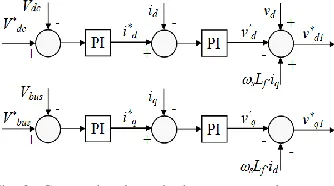
A. Standard Vector Control
[image:3.612.355.522.505.598.2]The conventional standard vector control method for the GCC, widely used in renewable and electric power system applications, has a nested-loop structure consisting of a faster inner current loop and a slower outer loop, as shown in Fig. 3 [3, 4, 11]. In this figure, the d-axis loop is used for dc-link voltage control, and the q-axis loop is used for reactive power or grid voltage support control. The control strategy of the inner current loop is developed by rewriting Eq. (1) as:
1
d d d s q d
v Ri L di dt
Li v (8)
1
q q q s d
v Ri L di dt
Li (9) in which the bracketed item in Eqs. (8) and (9) is treated as the transfer function between the input voltage and output current for the d and q loops, and the other terms are treated as compensation items [3, 4, 11]. This treatment assumes that vd1 in Eq. (8) has no major influence on iq and that vq1in Eq. (9) has no important effect on id.
Fig. 3. Conventional standard vector control structure
Nevertheless, this assumption is inadequate [14, 15]. According to Fig. 3, the final control voltages, vd1* and vq1*, linearly proportional to the converter output voltages, Vd1 and
Vq1, include the d and q voltages, vd’ and vq’, generated by the current-loop controllers in addition to the compensation terms, as shown by Eq. (10). Hence, this control configuration intends to regulate idand iq using vd’ and vq’, respectively. On the other hand, according to Eqs. (7), (4) and (5), the d-axis voltage is effective only for reactive power, or iq control, and
the q-axis voltage is effective only for active power, or id
on the compensation terms rather than the PI loops to regulate the d- and q-axis currents via a competing control strategy. However, those compensation terms are not included in the feedback control principle, which could result in malfunctions of the overall system [14].
* '
1
* '
1
d d s f q d
q q s f d
v v L i v
v v L i
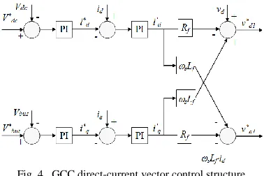
(10)B. Direct-Current Vector Control
[image:4.612.80.269.395.521.2]The DCC vector control method [14, 15], developed recently to overcome the deficiencies of the conventional standard vector control techniques, is considered a pilot adaptive vector control strategy. The theoretical foundation of the DCC is expressed in Eqs. (4) and (5), i.e., the use of d- and q-axis currents directly for active and reactive power control of the GCC system. Unlike the conventional approach that generates a d- or q-axis voltage from a GCC current-loop controller, the direct-current vector control structure outputs a current signal at the d- or q-axis current-loop controller (Fig. 4). In other words, the output of the controller is a d or q tuning current, while the input error signal tells the controller how much the tuning current should be adjusted during the dynamic control process. The development of the tuning current control strategy has adopted intelligent control concepts [15], e.g., a control goal to minimize the absolute or root-mean-square (RMS) error between the desired and actual d- and q-axis currents through an adaptive tuning strategy.
Fig. 4. GCC direct-current vector control structure
Due to the nature of a voltage-source converter, the d- and q-axis tuning current signals, id’ and iq’, generated by the current-loop controllers must be transferred to d- and q-axis voltage signals vd1
*
and vq1 *
to control the GCC. This is realized through Eq. (11), which is equivalent to the transient d-q equation, Eq. (1), after being processed by a low pass filter in order to reduce the high oscillation of d and q reference voltages applied directly to the converter.
* ' '
1
* ' '
1
d f d s f q d
q f q s f d
v R i L i v
v R i L i
(11)
The initial values of the DCC PI current-loop controllers are tuned by minimizing the RMS error between the reference and measured values. Nonetheless, a major challenge of the DCC is that no well-established systematical approach exists
for tuning the controller PI gains, so an optimal DCC controller is extremely difficult to achieve.
IV. STRUCTURE OF GCCVECTOR CONTROL USING
ARTIFICIAL NEURAL NETWORKS
To develop a neural-network-based vector controller, the integrated GCC and grid system model from Eq. (1) is first rearranged into the standard state-space representation as shown by:
1
1
1 1
d f f s d d d
q s f f q f q f q
i R L i v v
d
i R L i v v
dt L L
(12)
where the system statesare idand iq, grid PCC voltages vdand
vq are normally constant, and converter output voltages vd1and
vq1 are proportional to the control voltage of the action neural network. The ratio of the converter output voltage to the control voltage is a gain of kPWM, i.e., the gain of the voltage source dc/ac PWM converter [30]. For digital control implementation and the offline training of the neural network, the discrete equivalent of the continuous system state-space model from Eq. (12) must be obtained as shown by:
11
d s s d s d s d
q s s q s q s q
i kT T i kT v kT v
i kT T i kT v kT v
F G (13)
where Ts represents the sampling period, F is the system matrix, and G is the input matrix. In this paper, a zero-order-hold discrete equivalent mechanism [31] is used to convert the continuous state-space model of the system from Eq. (12) to the discrete state-space model in Eq. (13). We used Ts=0.001sec in all experiments.
Hence, the overall neural-network-based vector control structure of the GCC current-loop is shown in Fig. 5. In the figure, the action neural network contains four inputs, of which two represent the measurements of GCC d- and q-axis currents, and the other two are the error signals between the desired and actual d- and q-axis currents (i.e., id*-idand iq*-iq).
Fig. 5.Neural vector control structure of GCC current loop
The neural network, known here as the action network, was a multi-layer perceptron [32] with 4 input nodes, 2 hidden layers of 6 nodes each, and 2 output nodes. Hyperbolic tangent functions were used as the activation function at all nodes. The first two input nodes receive an input of tanhidq 1000, and
the second two input nodes receive an input of
*
[image:4.612.319.562.500.592.2]V. TRAINING NEURAL NETWORK FOR OPTIMAL VECTOR
CONTROL OF A GCC
A. Dynamic Programming in GCC Vector Control
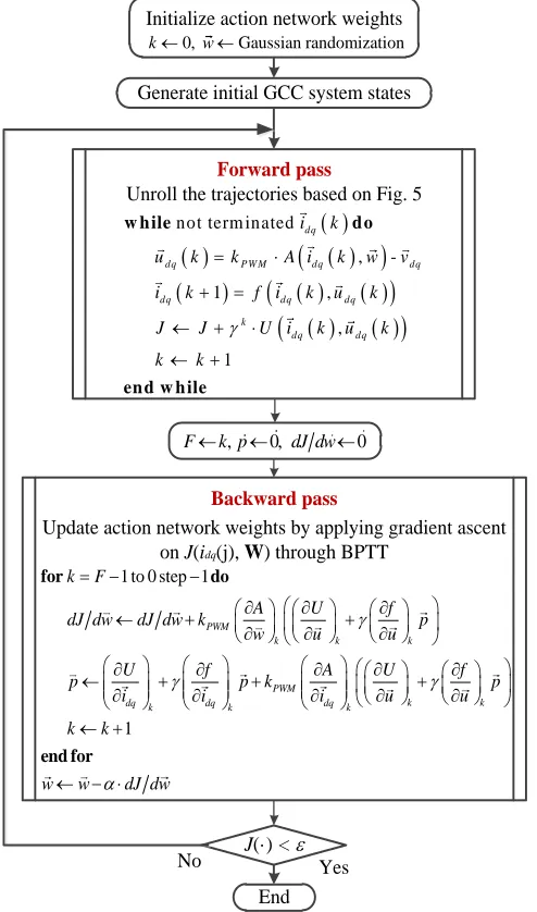
Dynamic programming employs the principle of optimality and is a very useful tool for solving optimization and optimal control problems. According to [20], the principle of optimality is expressed as: ―An optimal policy has the property that whatever the initial state and initial decision are, the remaining decisions must constitute an optimal policy with regard to the state resulting from the first decision.‖ The typical structure of the time DP includes a discrete-time system model and a performance index or cost associated with the system [23].
Initialize action network weights
Generate initial GCC system states
Forward pass
Unroll the trajectories based on Fig. 5
Backward pass
Update action network weights by applying gradient ascent on J(idq(j), W) through BPTT
J(·) < e
End No Yes
0, Gaussian randomization
k w
not term inated
,
-1 ,
,
1
w h ile d o
en d w h ile
dq
dq P W M dq dq
dq dq dq
k
dq dq i k
u k k A i k w v
i k f i k u k
J J U i k u k
k k
, 0, 0
F k p dJ dw
1 to 0 step 1
for do
PWM
k k k
PWM
k k
dq k dq k dq k k F
A U f
dJ dw dJ dw k p
w u u
U f A U f
p p k p
i i i u u
k
1
end for
k
w w dJ dw
[image:5.612.55.302.221.640.2]Fig. 6. DP based BPTT algorithm for GCC Vector control
For the neural-network-based vector control structure of the GCC, as shown in Fig. 5, the discrete system model of Eq. (13) can be rewritten in the following simplified way:
1
,
F
G
.dq dq dq dq dq
i k f i k u k i k u k (14) Under a constant dq reference current, the control action applied to the system is expressed by:
1
-
,
- .dq dq dq PWM dq dq
u k v k v k A i k w v (15) where w is the weight vector of the action network, and A() stands for the action network, as described in section IV.
The DP cost function associated with the vector-controlled system is:
,
k j
,
dq dq dq
k j
J i j w
U i k u k
(16) where is the discount factor with 0 ≤ ≤ 1, and U() is defined as
2
2* *
,
dq dq d d q q
U i k u k i k i i k i . (17) The function J(), dependent on the initial time j and the initial state idq
j , is referred to as the cost-to-go of state
dq
i j in the dynamic programming problem. The objective of the DP problem is to choose a vector control sequence,
dq
u k , k=j, j+1, ... , so that the function J() in Eq. (16) is minimized.
B. Backpropagation Through Time Algorithm
The action network was trained to minimize the DP cost of Eq. (16) by using the backpropagation through time (BPTT) algorithm [33]. BPTT is gradient descent onJ i
dq
j ,w
with respect to the weight vector of the action network. BPTT can be applied to an arbitrary trajectory with an initial state idq(j), and thus be used to optimize the vector control strategy. In general, the BPTT algorithm consists of two steps: a forward pass which unrolls a trajectory, followed by a backward pass along the whole trajectory which accumulates the gradient descent derivative. Figure 6 shows the block diagram and pseudocode for this whole process. In this figure, the vector and matrix notation is such that all vectors are columns; differentiation of a scalar by a vector gives a column. Differentiation of a vector function by a vector argument gives a matrix, such that for example (dA/dw)ij=dAj/dwi.In Fig. 6, the subscripted k variables on parentheses indicate that a quantity is to be evaluated at time step k.The BPTT pseudocode requires the derivatives of the functions f() and U(), which were found directly by differentiating equations 14 and 17, respectively. Hence we were using the exact models of the plant – there was no need for a separate system identification process or separate model network. For the termination condition of a trajectory, we used a fixed trajectory length corresponding to a real time of 1 second (i.e. a trajectory had 1/Ts=1000 time steps in it). We used =1 for the discount factor.
C. Training the Neural Controller
The training procedure includes 1) randomly generating a sample initial state idq(j), 2) randomly generating a sample reference dq current, 3) unrolling the trajectory of the GCC system from the initial state, 4) training the action network based on the DP cost function in Eq. (16) and the BPTT training algorithm, and 5) repeating the process for all the sample initial states and reference dq currents until a stop criterion associated with the DP cost is reached (Fig. 6). The weights were initially all randomized using a Gaussian distribution with zero mean and 0.1 variance. Training used RPROP [34] to accelerate learning, and we allowed RPROP to act on 10 trajectories simultaneously (each with a different start point and idq*).
[image:6.612.318.543.126.243.2]Fig. 7. Average total DP cost per trajectory time step for training GCC vector [image:6.612.55.295.209.331.2]
controller
Figure 7 shows the average DP cost per trajectory time step for training the action neural network, in which both the initial states and reference dq currents are generated randomly around using Gaussian distribution. Regarding the Gaussian distribution of the initial states, the mean for d-axis current is 100A, the mean for q-axis current is 0A, and the variance for both d and q-axis currents is 10A. Regarding the Gaussian distribution of the reference dq currents, the means for the d and q-axis currents are the same but the variance is 50A. Each trajectory duration was unrolled during training for a duration of 1 second, and the reference dq current was changed every 0.1 seconds. As the figure indicates, the overall average DP cost dropped to around zero very quickly, demonstrating the strong learning ability of the optimal neural controller for the vector control application.
VI. PERFORMANCE EVALUATION OF TRAINED NEURAL
VECTOR CONTROLLER
A. Ability of the Neural Controller to Trace the Reference Current
To assess the performance of the vector control approach using artificial neural networks, the integrated controller and the dc/ac converter system are tested for the system configuration, as shown in Fig. 5. In the figure, initial system states can be generated randomly and are far away from the primary population of the training trajectories and the reference dq currents can change to random values that are not used in the training of the neural network. Figure 8 demonstrates the behavior of the neural controlled GCC system. At the beginning, both GCC d- and q-axis currents are zero, and the d and q-axis reference currents are 100A and 0A, respectively. After the start of the system, the neural controller
quickly regulates the d- and q-axis currents to the reference values. When the reference dq current changes to new values at t=0.5s and t=1s, the neural controller restores d- and q-axis current to the reference currents immediately. The experiments show that the neural controller can be applied successfully in GCC vector control problems.
Fig. 8. Performance of neural vector controller to the trace reference current
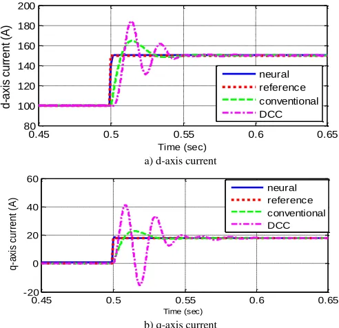
B. Comparison of Neural Controller with Conventional Standard and DCC Vector Control Mechanisms
For the comparison study, the current-loop PI controller is designed by using the conventional standard vector control technique and the direct-current vector control approach, respectively, as shown in Section III. For the conventional standard vector control structure (Fig. 3), the gains of the PI controller is designed based on the transfer function, as shown in Eqs. (8) and (9) [7]. For the direct-current vector control structure (Fig. 4), the gains of the PI controller is tuned until the controller performance is acceptable [14]. The parameters of the GCC system are the same as those used in Section V-C.
a) d-axis current
[image:6.612.316.562.412.650.2]b) q-axis current
Fig. 9. Comparison of conventional, DCC and neural vector controllers
Figure 9 presents a comparison study for conventional, DCC, and neural vector controllers under the same conditions as in Fig. 8. The figure indicates that among the three vector control strategies, the neural controller has the fastest response time, low overshoot, and best performance. For many other reference current conditions, the comparison study
0 50 100 150 200 250 300
100 101 102 103 104
Av
era
ge T
ota
l Co
st
# of Iteration
0 0.25 0.5 0.75 1 1.25 1.5 -50
0 50 100 150 200
C
u
rr
e
n
t
(A
)
Time (sec)
Id Id* Iq Iq*
0.45 0.5 0.55 0.6 0.65
80 100 120 140 160 180 200
d-axis
cu
rrent
(A
)
Time (sec)
neural reference conventional DCC
0.45 0.5 0.55 0.6 0.65
-20 0 20 40 60
q
-a
xi
s
cu
rr
e
n
t
(A
)
Time (sec)
demonstrates that the neural vector controller performs better than both conventional and DCC vector control mechanisms.
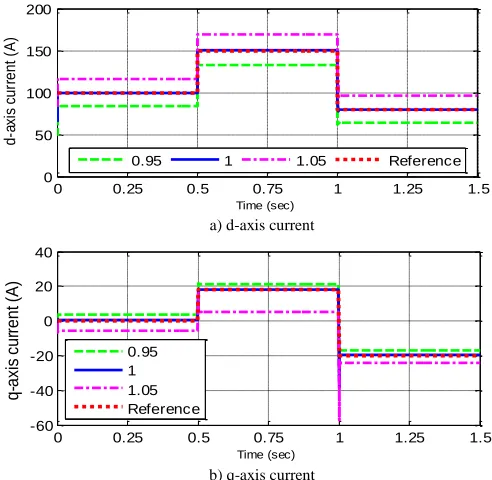
C. Performance Evaluation under Variable Parameters of GCC System
GCC stability has been one of the main issues to be investigated in conventional GCC vector control. In general, such studies primarily focus on the GCC performance under system parameter changes or for variable ac system voltage conditions. For instance, in [1], a small-signal model is used for a sensitivity study of the GCC under variable system parameter conditions. In [33], a control strategy is developed to improve the GCC performance under variable system conditions.
a) d-axis current
[image:7.612.316.562.88.328.2]b) q-axis current
Fig. 10. Performance of neural vector controllers under variable grid-filter inductance conditions
In this paper, the neural vector control technique is evaluated for two variable GCC system conditions, namely, 1) variation of grid-filter resistance and inductance, and 2) variable PCC voltage. Figure 10 compares how the neural control strategies are affected when there is an increase or decrease of R and L values by 30% from the initial values. Figure 11 compares how the neural vector control approaches are affected by a 5% voltage fluctuation away from the rated ac power supply system voltage. The study shows that the neural controller is affected very little by the change of grid-filter resistance. However, for a change of grid-grid-filter inductance, the neural controller may be unable to trace the reference dq current effectively (Fig. 10). In general, a deviation of the grid-filter inductance above its initial value causes the controlled d and q currents stabilizing at a value that is higher than the reference value while a deviation of the grid-filter inductance below its initial value causes the d and q currents stabilizing at a value that is smaller than the reference value. Similar to the situation for the grid-filter inductance, the fluctuation of PCC voltage also causes the controlled dq current unable to stabilize at the reference value, as shown in Fig. 11.
It is necessary to indicate that the training of the neural controller does not consider variable system parameters. This is an issue that will be addressed in the future research.
a) d-axis current
b) q-axis current
Fig. 11. Performance of neural vector controllers under variable PCC voltage conditions (1—rated voltage, 0.95—95% of the rated voltage, 1.05—105% of
the rated voltage)
VII. CONCLUSIONS
Three-phase grid-connected rectifier/inverters are used widely in renewable, microgrid and electric power system applications. This paper investigates conventional vector control approaches for the grid-connected converters and analyzes the limitations associated with conventional vector control methods. Then, a neural-network-based vector control method is presented. The paper describes how dynamic-programming (DP) methods are employed to train the neural network through a backpropagation through time algorithm.
One of the main results is that the associated cost drops very quickly as training progresses, demonstrating the strong learning capability of the neural network for the vector control application. The performance evaluation shows that the neural controller can trace the reference d and q-axis currents effectively even for testing trajectories and reference currents that are far away from the training data set. Compared to the conventional standard vector control method and a recently developed direct-current vector control technique, the neural vector control approach produces the fastest response time, low overshoot, and, in general, the best performance.
However, if the GCC system parameters are not constant, the performance of the GCC system could be affected. This is particularly evident for variable grid-filter inductance and fluctuating PCC voltage conditions, which normally renders the neural controller unable to trace the reference dq current effectively. To improve the performance of the neural vector controller for more practical vector control conditions, it is important to research and develop enhanced neural vector control architectures and training strategies.
0 0.25 0.5 0.75 1 1.25 1.5 50
75 100 125 150 175 200
d
-a
xi
s
cu
rr
e
n
t
(A
)
Time (sec)
L=1.4mH L=2mH L=2.6mH reference
0 0.25 0.5 0.75 1 1.25 1.5
-50 -25 0 25
q-axis
cu
rrent
(A
)
Time (sec)
L=1.4mH L=2mH L=2.6mH reference
0 0.25 0.5 0.75 1 1.25 1.5
0 50 100 150 200
d
-a
xi
s
cu
rr
e
n
t
(A
)
Time (sec)
0.95 1 1.05 Reference
0 0.25 0.5 0.75 1 1.25 1.5
-60 -40 -20 0 20 40
q-axis
cu
rrent
(A
)
Time (sec)
[image:7.612.52.300.222.445.2]VIII. REFERENCE
[1] E. Figueres, G. Garcera, J. Sandia, F. Gonzalez-Espin, and J.C. Rubio, ―Sensitivity Study of the Dynamics of Three-Phase Photovoltaic Inverters With an LCL Grid Filter,‖ IEEE Transactions on Industrial Electronics, Vol. 56, No. 3, March 2009, pp. 706-717. [2] C. Wang, and M.H. Nehrir, ―Short-Time Overloading Capability and
Distributed Generation Applications of Solid Oxide Fuel Cells,‖ IEEE Trans. on Energy Conversion, Vol. 22, No. 4, Nov. 2007, pp. 898-906. [3] A. Luo, C. Tang, Z. Shuai, J. Tang, X. Xu, and D. Chen, ―Fuzzy-PI-Based Direct-Output-Voltage Control Strategy for the STATCOM Used in Utility Distribution Systems,‖ IEEE Transactions on Industrial Electronics, Vol. 56, No. 7, July 2009, pp. 2401-2411.
[4] J. M. Carrasco, L. G. Franquelo, J. T. Bialasiewicz, E. Galván, R. C. P. Guisado, M. Á. M. Prats, J. I. León, and N. Moreno-Alfonso, ―Power-Electronic Systems for the Grid Integration of Renewable Energy Sources: A Survey,‖ IEEE Trans. On Industrial Electronics, Vol. 53, No. 4, August, 2006.
[5] L. Xu, and Y. Wang, ―Dynamic Modeling and Control of DFIG Based Wind Turbines under Unbalanced Network Conditions‖, IEEE Trans. on Power Systems, Vol. 22, No. 1, Feb. 2007.
[6] A. Mullane, G. Lightbody, and R. Yacamini, ―Wind-Turbine Fault Ride-Through Enhancement,‖ IEEE Trans. on Power Systems, Vol. 20, No. 4, Nov. 2005.
[7] R. Pena, J.C. Clare, and G. M. Asher, ―Doubly fed induction generator using back-to-back PWM converters and its application to variable speed wind-energy generation,‖ IEE Proc.-Electr. Power Appl., Vol. 143, No 3, May 1996, pp. 231-241.
[8] B. C. Rabelo, W. Hofmann, J. L. Silva, R. G. Oliveira, and S. R. Silva, ―Reactive Power Control Design in Doubly Fed Induction Generators for Wind Turbines,‖ IEEE Transactions on Industrial Electronics, Vol. 56, No. 10, October 2009, pp. 4154-4162.
[9] S. Li and T.A. Haskew, ―Transient and Steady-State Simulation of Decoupled d-q Vector Control in PWM Converter of Variable Speed Wind Turbines,‖ Proceedings of 33rd Annual Conference of IEEE Industrial Electronics (IECON 2007), Taipei, Taiwan, Nov. 5-8, 2007. [10] S. Li and T.A. Haskew, ―Analysis of Decoupled d-q Vector Control in
DFIG Back-to-Back PWM Converter,‖ Proceedings of IEEE Power Engineering Society 2007 General Meeting, Tampa FL, June 24-28, 2007.
[11] J. Dannehl, C. Wessels, and F. W. Fuchs, “Limitations of Voltage-Oriented PI Current Control of Grid-Connected PWM Rectifiers With
LCL Filters,‖ IEEE Transactions on Industrial Electronics, Vol. 56, No. 2, October 2009, pp. 380-388
[12] I. Codd, ―Windfarm Power Quality Monitoring and Output Comparison with EN50160‖, Proc. of the 4th Intern. Workshop on Large-scale Integration of Wind Power and Transmission Networks for Offshore Wind Farm, 20-21 Oct. 2003, Sweden.
[13] B. I. Nass, T. M. Undeland, and T. Gjengedal, ―Methods for Reduction of Voltage Unbalance in Weak Grids Connected to Wind Plants‖,
Proc. of the IEEE Workshop on Wind Power and the Impacts on Power Systems, Oslo, June 2002.
[14] Shuhui Li, Timothy A Haskew, Yang-Ki Hong, and Ling Xu, ―Direct-Current Vector Control of Three-Phase Grid-Connected Rectifier-Inverter,‖ Electric Power System Research (Elsevier), Vol. 81, Issue 2, February 2011, pp. 357-366.
[15] Shuhui Li, Tim Haskew, and Ling Xu, ―Control of HVDC Light Systems using Conventional and Direct-Current Vector Control Approaches,‖ IEEE Transactions on Power Electronics, Vol. 25, No. 12, December 2010, pp. 3106-3118.
[16] A. Al-Tamimi, M. Abu-Khalaf, and F. L. Lewis, ―Adaptive critic designs for discrete time zero-sum games with application to H` control,‖ IEEE Trans. Syst., Man, Cybern. B, vol. 37, no. 1, pp. 240– 247, Feb. 2007.
[17] S. N. Balakrishnan and V. Biega, ―Adaptive-critic-based neural networks for aircraft optimal control,‖ J. Guid. Control Dyn., vol. 19, pp. 893–898, July 1996.
[18] S. N. Balakrishnan, J. Ding, and F. L. Lewis, ―Issues on stability of ADP feedback controllers for dynamical systems,‖ IEEE Trans. Syst., Man., Cybern. B, vol. 38, no. 4, pp. 913–917, Aug. 2008.
[19] S. Mohahegi, G. K. Venayagamoorth, and R. G. Harley, ―Adaptive critic design based neuro-fuzzy controller for a static compensator in a
multimachine power system,‖ IEEE Trans. Power Syst., vol. 21, no. 4, pp. 1744–1754, Nov. 2006.
[20] R. E. Bellman, Dynamic Programming. Princeton, NJ: Princeton Univ. Press, 1957.
[21] Kirk, D. E., Optimal Control Theory: An Introduction, Prentice–Hall, Englewood Cliffs, NJ, 1970, Chaps. 1–3.
[22] D. V. Prokorov and D. C. Wunsch, ―Adaptive Critic Designs,‖ IEEE Transactions on Neural Networks, Vol. 8, No. 5, 1997, pp. 997–1007. [23] F.Y. Wang, H. Zhang, and D. Liu, "Adaptive dynamic programming:
An introduction," IEEE Computational Intelligence Magazine, pages 39–47, 2009.
[24] G. G. Lendaris, L. Schultz, and T. T. Shannon, ―Adaptive Critic Design for Intelligent Steering and Speed Control of a 2-Axle Vehicle,‖
Proceedings of the 2000 International Joint Conference on Neural Networks, Como, Italy, July 2000.
[25] D. Han, and S. N. Balakrishnan, ―Adaptive Critic Based Neural Networks for Control-Constrained Agile Missile Control,‖
Proceedings of the American Control Conference, San Diego, USA, June 2 - 4, 1999, pp. 2600–2604.
[26] G. Saini, and S. N. Balakrishnan, ―Adaptive Critic Based Neurocontroller for Autolanding of Aircraft,‖ Proceedings of the American Control Conference, Albuquerque, USA, June 4 - 6,1997, pp. 1081–1085.
[27] S. N. Balakrishnan and V. Biega, ―Adaptive-Critic-Based Neural Networks for Aircraft Optimal Control,‖ Journal of Guidance, Control, and Dynamics, Vol. 19, No. 4, 1996, pp. 893–898.
[28] K. KrishnaKumar and J. Neidhoefer, ―Immunized Adaptive Critics for Level-2 Intelligent Control,‖ Proceedings of the IEEE International Conference on Systems, Man and Cybernetics, Orlando, USA, Oct. 12 - 15,1997, pp. 856–861.
[29] Venayagamoorthy, G. K., Harley, R. G., and Wunsch, D. C., ―Comparison of Heuristic Dynamic Programming and Dual Heuristic Programming Adaptive Critics for Neurocontrol of a Turbogenerator,‖
IEEE Transactions on Neural Networks, Vol. 13, No. 3, 2002, pp. 764– 773.
[30] N. Mohan, T. M. Undeland, and W. P. Robbins, Power Electronics: Converters, Applications, and Design, 3rd Ed., John Wiley & Sons Inc.,
October 2002.
[31] Gene F. Franklin, J. David Powell, Michael L. Workman, " Digital control of dynamic systems," 3rd edition, Addison-Wesley, 1998. [32] Christopher M. Bishop, "Neural Networks for Pattern Recognition",
Oxford University Press, pages 55, 1995.
[33] Paul J. Werbos", "Backpropagation through time: What it does and how to do it", Proceedings of the IEEE, Vol. 78, No. 10, 1550-1560, 1990.
[34] Martin Riedmiller and Heinrich Braun, "A Direct Adaptive Method for Faster Backpropagation Learning: The RPROP algorithm", Proc. of the IEEE Intl. Conf. on Neural Networks", San Francisco, CA, pages 586--591, 1993.