Rochester Institute of Technology
RIT Scholar Works
Theses
Thesis/Dissertation Collections
12-1-2012
A Study of the use of SIMD instructions for two
image processing algorithms
Eric Welch
Follow this and additional works at:
http://scholarworks.rit.edu/theses
This Thesis is brought to you for free and open access by the Thesis/Dissertation Collections at RIT Scholar Works. It has been accepted for inclusion in Theses by an authorized administrator of RIT Scholar Works. For more information, please [email protected].
Recommended Citation
A Study of the use of SIMD Instructions for
Two Image Processing Algorithms
by
Eric Michael Welch
A Thesis Submitted in Partial Fulfillment of the Requirements for the Degree of
Master of Science
In
Electrical Engineering
Approved By:
______________________________________________________________________ Dr. Dorin Patru
Associate Professor, Department of Electrical and Microelectronic Engineering Thesis Advisor
______________________________________________________________________ Dr. Eli Saber
Professor, Department of Electrical and Microelectronic Engineering
______________________________________________________________________ Dr. Gill Tsouri
Assistant Professor, Department of Electrical and Microelectronic Engineering
______________________________________________________________________ Dr. Sohail Dianat
Department Head, Department of Electrical and Microelectronic Engineering
Department of Electrical and Microelectronic Engineering Kate Gleason College of Engineering
Rochester Institute of Technology Rochester, New York
Dedication
iii
Acknowledgements
I would like to thank my advisor Dr. Dorin Patru for his guidance and support; my
committee members Dr. Eli Saber and Dr. Gill Tsouri for their input on the
Abstract
Many media processing algorithms suffer from long execution times, which are most
often not acceptable from an end user point of view. Recently, this problem has been
exacerbated because media has higher resolution. One possible solution is through the
use of Single Instruction Multiple Data (SIMD) architectures, such as ARM’s NEON.
These architectures take advantage of the parallelism in media processing algorithms by
operating on multiple pieces of data with just one instruction. SIMD instructions can
significantly decrease the execution time of the algorithm, but require more time to
implement.
This thesis studies the use of SIMD instructions on a Cortex-A8 processor with
NEON SIMD coprocessor. Both image processing algorithms, bilinear interpolation and
distortion, are altered to process multiple pixels or colors simultaneously using the
NEON coprocessor’s instruction set. The distortion algorithm is also altered at the
assembly level through the removal of memory accesses and branches, adding data
prefetch instructions, and interlacing ARM and NEON instructions. Altering the
assembly code requires a deeper understanding of the code and more time, but allows
for more control and higher speedups. The theoretical speedup for the bilinear
interpolation and distortion algorithms is three and four times respectively. The actual
measured speedup for the bilinear interpolation algorithm is more than two times, and for
the distortion algorithm is more than three times. The results show that SIMD
instructions can provide a speedup to image processing algorithms following a correct
v
Contents
Dedication ... ii
Acknowledgements ... iii
Abstract ... iv
Contents ... v
List of Figures ... vii
List of Tables ... viii
1 Introduction ... 1
2 Background ... 3
2.1 SIMD Instruction Set Extensions ... 3
2.2 NEON SIMD Architecture ... 5
2.3 Image Processing using SIMD instructions ... 7
3 Description of System ... 9
3.1 Hardware Setup ... 9
3.2 Software Setup ... 11
3.3 Algorithms under Investigation ... 12
3.3.1 Bilinear Interpolation Algorithm ... 12
3.3.2 Distortion Algorithm ... 14
4 Experimental Procedure ... 18
4.1 Bilinear Interpolation Tests ... 18
4.1.1 NEON1 Test ... 18
4.1.2 NEON2 Test ... 20
4.2 Distortion Tests ... 21
4.2.1 NEON1 Test ... 22
4.2.2 NEON2 Test ... 23
4.2.3 NEON3 Test ... 24
4.2.5 ASM1 Test ... 26
4.2.6 ASM2 Test ... 28
4.2.7 ASM3 Test ... 28
4.2.8 32-bit to 16-bit test ... 30
4.2.9 Integer and Floating Point Test ... 30
4.2.10 ARM and NEON Test ... 31
4.2.11 Revised Baseline Test ... 31
5 Results and Discussions ... 32
5.1 Bilinear Interpolation Results ... 32
5.2 Distortion Results ... 38
5.2.1 Main Results ... 38
5.2.2 Other Considerations ... 44
5.3 Power Assessment ... 48
5.4 Contributions ... 49
6 Conclusions ... 53
References ... 54
A Performance Counter Code ... 56
B Bilinear Interpolation Baseline Code ... 58
C Bilinear Interpolation NEON1 Code ... 60
vii
List of Figures
2.1 Example of SIMD Addition ... 4
2.2 ARM and NEON Pipeline for the Cortex-A8 ... 5
2.3 Partitioning of Quad Registers into Double Registers ... 6
3.1 Bilinear Interpolation Example ... 13
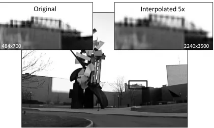
3.2 Example Image Interpolated by a Factor of 5 ... 13
3.3 Distortion Algorithm’s Baseline Results ... 15
3.4 Distortion Algorithm’s Program Flow ... 17
4.1 Bilinear Interpolation’s Program Flow for NEON1 ... 19
4.2 Bilinear Interpolation NEON1’s SIMD Register Setup ... 20
4.3 Bilinear Interpolation’s Program Flow for NEON2 ... 21
4.4 Distortion Algorithm’s Program Flow for the NEON1 Test ... 22
4.5 Distortion Algorithm’s SIMD Register Setup ... 23
4.6 Distortion Algorithm’s Program Flow for the NEON2 Test ... 24
4.7 Distortion Algorithm’s Program Flow for the NEON3 Test ... 25
4.8 Distortion Algorithm’s Program Flow for the ASM1 Test... 27
4.9 Distortion Algorithm’s Program Flow for the ASM2 Test... 29
5.1 Bilinear Interpolation’s Speedup with Different Interpolation Factors ... 32
5.2 Bilinear Interpolation’s L2 Cache Events ... 34
5.3 Bilinear Interpolation’s Branch Mispredictions ... 35
5.4 Bilinear Interpolation’s Full NEON Queue Stalls ... 36
5.5 Bilinear Interpolation’s Both Processors Active ... 36
5.6 Bilinear Interpolation Speedup with Five Different Images ... 37
5.7 Distortion Algorithm’s Speedup Relative to Baseline ... 39
5.8 Distortion Algorithm’s L2 Cache Events ... 40
5.9 Distortion Algorithm’s Branch Mispredictions ... 41
5.10 Distortion Algorithm’s Both Processors Active ... 42
5.11 Distortion Algorithm’s Full NEON Queue Stalls ... 43
5.12 Distortion Algorithm’s Coprocessor to Processor Transfer Stalls ... 44
5.13 16-bit Distortion Test Result ... 45
5.14 Integer and Floating Point Distortions Results ... 45
5.15 Distortion’s Image Error Compared to Baseline Image ... 47
List of Tables
2.1 Instruction Cycle Timing... 6
2.2 Results from Intel SSE Study ... 8
5.1 Distortion Algorithm’s Power Consumption ... 49
Chapter 1
Introduction
The time required to process media, such as images and audio, has become
increasingly longer over the past few years due to the increase in resolution. The speed
of computing processors has not kept up with the time required to process images. One
solution to this problem is the implementation of Single Instruction Multiple Data (SIMD)
instruction sets. The SIMD instructions operate on multiple data with just one instruction.
Instructions can be applied to data sets of four or more operands simultaneously. SIMD
architectures, such as Intel’s WMMX and SSE and ARM’s NEON, can exploit the
parallelism present in many image processing algorithms by operating on multiple pixels
at a time. This can significantly increase the speed of algorithms by a factor of two or
more, but additional time is required to implement the instructions.
An ARM processor is used in many embedded applications such as cellular phones,
televisions, and printers. An ARM processor is a 32-bit Reduced Instruction Set
Computer (RISC) with a load/store architecture. The processor’s architecture is licensed
from ARM and implemented by manufacturers such as Texas Instruments, Marvell, and
others. The manufacturers implement the architecture, add custom components, and
manufacture the processor. Advantages of an ARM processor include a simple unified
design and low power consumption. The unified design allows programmers to easily
change from one processor manufacturer to another without learning a new instruction
set. The ARM processors aim to be high performance with low power consumption. The
low power consumption is ideal for mobile devices, which often have a limited supply of
battery power.
Recently, ARM processors have included two SIMD options, ARMv6 SIMD and
NEON SIMD. The ARMv6 SIMD is included in the ARMv6 architecture and above.
These SIMD instructions operate on the traditional 32-bit ARM registers, and can
process up to four 8-bit operands at a time. The ARMv7 architecture introduced the
NEON SIMD coprocessor in the Cortex-A8. This coprocessor is separate from the ARM
processor and can process up to sixteen 8-bit operands at a time. The NEON
coprocessor contains four times the capacity of the ARMv6 SIMD, which can increase
Combining the ARM processor with the NEON SIMD coprocessor is ideal for
embedded systems. Most embedded systems, such as cellular phones and printers,
perform large amounts of media and data processing. In most cases, the user requires
this processing to occur quickly, which is possible with SIMD instructions. Because most
embedded systems already include an ARM based processor, changing to an ARM
based processor with NEON coprocessor is trivial. The hardware may have to be altered
slightly, but the software can remain mostly the same. The only major change is
rewriting the code to include the SIMD instructions, which can be time consuming. The
main drawback of using SIMD instructions is the increased development time.
Previous studies on the use of SIMD instructions produced a speedup of less than
three times. This thesis demonstrates how a speedup of greater than three times can be
attained using SIMDs and other optimization techniques. The remainder of this thesis
focuses on the implementation of NEON SIMD instructions on a bilinear interpolation
algorithm and a distortion algorithm. The remaining chapters are organized as follows:
Chapter 2 describes SIMD instructions, the NEON instruction set, and previous works
related to SIMD image processing. Chapter 3 describes the hardware and software
setup used, and the two algorithms used for testing. Chapter 4 presents the various test
cases for both algorithms. Chapter 5 presents and discusses the results from all the test
cases. Chapter 6 concludes the thesis with concluding remarks, and ideas for possible
Chapter 2
Background
In the past few years, more emphasis has been placed on multimedia processing in
computers. Image and audio files have become higher resolution, which requires more
processing time than lower resolution files. To counteract the increased processing time,
single instruction multiple data (SIMD) instruction set extensions have been developed
to process more data during each instruction cycle. Section 2.1 explains the SIMD
instructions, followed by section 2.2 which explains the NEON SIMD instructions from
ARM, and finally section 2.3 explains how SIMD instructions can be specifically applied
to image processing.
2.1 SIMD Instruction Set Extensions
SIMD instruction set extensions have become more popular over the years, and are
being included in most current computer processors. Each SIMD instruction processes
multiple data during its execution. The SIMD architecture can be implemented in two
ways, modifications to the main processor or the addition of a coprocessor. The former
uses the main processor’s 32 or 64 bit registers with small modifications to the functional
units. The latter adds an additional coprocessor with separate larger 128 or 256 bit
registers and functional units. When operating on the main processor’s registers, very
little additional hardware is needed for implementation. Using a coprocessor architecture
requires larger registers and larger functional units, which adds additional hardware and
complexity to the design. However, each instruction is able to process more data
compared to the main processor architecture.
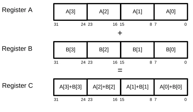
SIMD registers are divided into multiple lanes of 8 bits to 32 bits. Because most
multimedia processing occurs with either 8 or 16 bit operands, up to 32 operands can be
processed at a time with 256-bit registers . Figure 2.1 shows an example of addition
using 32-bit registers divided into four lanes of 8 bits. Each individual lane of register A is
added to each individual lane of register B to form the result in register C. Normally, this
addition would require four instructions and four cycles to complete, but the SIMD
a speedup of four times, which is fairly significant if this operation is occurring in a large
loop.
Using SIMD instructions is typically more time consuming than writing non-SIMD
code. For example, one has to ensure that each operand is in the correct lane and
enough space is available to complete the operation. SIMD libraries or coding in
assembly is often the best way to use the instructions. The libraries have functions that
compile into SIMD instructions, which make writing the code easier. This allows the
programmer to modify just the parts of the C code that need to be parallelized. To
achieve best performance, SIMD instructions should be written at the assembly level. At
this level, one has more control over what operands are in each register and can better
optimize for performance. Since writing assembly code is even more time consuming
and difficult, it is often done only when high performance is needed. Increasingly,
compilers are able to vectorize loops and code SIMD instructions directly. Vectorizing a
loop involves removing loop iterations with the use of SIMD instructions. The vectorizing
compilers are still being developed and currently only vectorize about half of the possible
loops .
SIMD instructions can significantly decrease the processing time of programs which
are parallelizable. Although, speedups of four or eight times are theoretically possible,
practically these will be less. Overhead involved with using the instructions as well as
non-vectorizable parts of the code will cause the speedup to be less than theoretical.
The benefits of using SIMD instructions come with a cost. More time will be needed to
implement these programs and the programmer will have to be more aware of how the Register A
Register B
A[3] A[2] A[1] A[0]
31 24 23 16 15 8 7 0
B[3] B[2] B[1] B[0]
31 24 23 16 15 8 7 0
+
A[3]+B[3] A[2]+B[2] A[1]+B[1] A[0]+B[0]
31 24 23 16 15 8 7 0
=
[image:13.612.152.477.81.269.2]Register C
operations can be executed in parallel. For some applications, the cost may outweigh
the benefit, but for others this potential speedup is critical for the success of the
program.
2.2 NEON SIMD Architecture
Many different SIMD architectures have been developed by different companies for use
in their processors. ARM processors implement the NEON SIMD architecture, which
consists of a coprocessor that is included in all Cortex-A8 processors and optional in
Cortex-A9 processors . The full Cortex-A8 ARM and NEON pipeline is shown in Figure
2.2. The ARM processor fetches SIMD instructions from the L1 instruction cache, and
forwards them to the NEON coprocessor, which then decodes and executes the
instructions. The coprocessor contains an integer Arithmetic Logic Unit (ALU), multiply
unit, shift unit, and a floating point addition and multiply unit. The coprocessor and
processor’s pipelines are 13 stages deep and all the functional units are pipelined to
[image:14.612.113.512.84.370.2]ability to access the data in either the L1 data cache or L2 cache. It also has a separate
register file from the ARM processor consisting of either 32 64-bit registers or 16 128-bit
registers. The 128-bit quad registers are partitioned in half to create two 64-bit double
registers as shown in Figure 2.3. The quad registers are labeled as q0 through q15, and
the double registers are labeled as d0 through d31. These registers can be split into
lanes consisting of 8, 16, 32, or 64 bits, and contain signed or unsigned integers,
floating-point numbers, or polynomials .
Coding using NEON SIMD instructions must be done to fully utilize the processor
and avoid hazards which can cause stalls. Table 2.1 shows most instructions, with the
exception of multiplication, complete in one cycle. Also, the functional units are
pipelined, therefore structural and data hazards do not occur very often. However, stalls
can occur when moving data from the coprocessor to the ARM processor, or when the
ARM and NEON load/store units access the same cache line. The former will cause a
stall of 20 cycles for both the ARM and NEON pipelines. The latter can cause a stall of
up to 20 cycles to handle cache ordering issues. The processor also has the option to
dual issue instructions. This involves issuing two instructions in the same cycle, but one
of the instructions must be either a load/store or a data move between processor and
Instruction Type Instruction Example Number of Cycles
ALU AND, SUB, MOV, ADD 1
Multiply MUL, MLA 2
Load/Store LDR, STR 1
NEON ALU VADD, VAND, VSUB 1
NEON Multiply VMUL, VMLA 4
NEON Load/Store VLD1, VST1 2
NEON Conversion VCVT 2
Quad Register “q”
d1
127 64 63 0
d0
q0
Double Register “d”
Figure 2.3: Partitioning of Quad Registers into Double Registers
coprocessor registers. Because of the large strides SIMD instructions take when
processing data, the NEON coprocessor also has access directly to the L2 cache. If an
L2 cache miss occurs from the NEON pipeline, then the main memory will be accessed
and only the L2 cache will be filled .
2.3 Image Processing using SIMD instructions
Image processing speed can be significantly increased using SIMD instructions. Most
images contain many pixels which are sequentially stored in memory. Each pixel
consists of one or more 8-bit integer values which describe the intensity of the color(s) in
the image. There is one color channel for black and white images and usually three color
channels for color images. With non-SIMD image processing, the 8 bits only fill a quarter
of the standard 32-bit register. Any operations on this register work on the full 32 bits,
and therefore, some of the processing is done on the unneeded 24 bits. Many image
algorithms are linear, and thus, the result from one pixel calculation does not affect other
pixels . SIMD takes advantage of this parallelism by placing multiple sequential pixels
into one register, and processing occurs on these pixels concurrently.
Theoretically, SIMD instructions could produce a speedup factor of four to eight
times when used with image processing . They have already been shown to provide
speedups of 1.25 to 2 times in video processing algorithms , . This is significantly below
the theoretical four times speedup, but it is still fairly significant for some algorithms.
Speeding up algorithms can also effect power consumption. If the processor finishes the
task much sooner, then it will have more time to go into low power mode and thus
decrease power consumption. Also, if a processor and coprocessor are concurrently
active, then the energy consumption may increase during that time. Speeding up any
algorithm could significantly affect the end user with faster processing and decreased
power consumption.
Intel’s SIMD instructions are known as Streaming SIMD Extensions (SSE), and they operate in a similar way to ARM’s NEON. These instructions can be used for image and
digital signal processing in Intel’s processors. The SSE architecture replaced the MMX
architecture and includes eight 128-bit registers for integer or floating-point numbers.
One study used the SSE instructions to speed up the algorithms for a sepia filter and
crossfade filter. The former converts an image to sepia tone, and the latter fades
together two separate images. Because the filters work on uncorrelated pixels, the
per iteration using SEE, and therefore, the theoretical speedup is four. Table 2.2 shows
SIMD extensions provide an actual speedup of about 2.6 to 2.7 times for an integer only
approach with the sepia filter depending on the resolution. The crossfade filter algorithm
produced a speedup of about 1.9 times depending on the resolution.
These studies prove that SIMD extensions can increase the performance of image
and video processing algorithms depending on the image size, although the actual
speedup so far is much lower than the theoretical speedup.
Filter Integer Speedup Floating-point Speedup
Sepia 2.6 1.9
Crossfade 2.7 1.9
Chapter 3
Description of System
The use of SIMD instructions is tested on an ARM processor containing a NEON
coprocessor with two image processing algorithms. Section 3.1 and 3.2 describes the
hardware and software setups, respectively, used for testing. Section 3.3 describes the
bilinear interpolation and distortion algorithms used in implementing the SIMD
instructions.
3.1 Hardware Setup
A BeagleBone prototyping board from beagleboard.org was chosen because of its use
of a Texas Instruments AM3359 Cortex-A8 processor. The BeagleBone board can
directly connect to the host PC using a standard USB-A to USB-mini connector or via an
optional JTAG connector. The USB client allows Secure Shell (SSH) terminal access
and SSH File Transfer Protocol (SFTP) file transfer between the host PC and
BeagleBone board. The board contains 256 MB of random access memory and a 2 GB
microSD card, which provides plenty of memory for image processing. The microSD
card comes preloaded with the Angstrom distribution of the Linux kernel version 3.2.14.
The kernel allows programs to be easily compiled and provides easy file manipulations.
The board also includes Ethernet and USB host ports, which allows for file transfer and
installation of new packages .
The AM3359 processor runs at 500 Mhz when powered via USB and 720 Mhz when
powered by an external power supply. The processor includes 32 KB each of L1
instruction cache and L1 data cache, and 256 KB of L2 cache. The L1 and L2 caches
are 4-way and 8-way set associative, respectively, and have a line size of 64 bytes. The
L2 cache has a 128-bit interface to the main memory, which corresponds to the size of
the NEON registers. The processor’s bootloader is stored 176 KB ROM, and is used to
start the Linux kernel .
The Cortex-A8 is built on the ARMv7 RISC architecture, which includes 14 general
purpose registers, one link register, one program counter (PC) register, and one Current
Program Status Register (CSPR). The general purpose registers can hold any data or
with link instruction is performed, or can be used as a general purpose register. When
returning from a branch, the value from the link register is loaded into the PC register.
The PC contains the address of the instruction to be issued next to the processor. The
CSPR contains condition flags, such as overflow and carry, and the current mode of the
processor. The architecture can execute either ARM or Thumb instructions. The former
is the standard 32-bit instruction set included on ARM processors, and the latter is a
compressed 16-bit instruction set, which allows more compact code to be compiled.
The Cortex-A8 includes program flow prediction, NEON advanced SIMD
coprocessor, vector floating point (VFP) coprocessor, dual issue pipeline, and four
performance counters. Program flow prediction is used to help avoid branch misses, and
includes a 512-entry 2-way set associative branch target buffer. Each branch miss incurs
a 13-cycle penalty because the pipeline must be flushed. Therefore, branch misses must
be kept to a minimum. The NEON SIMD instructions were discussed previously in
section 2.2. The VFP coprocessor is a floating point architecture that allows for fast
floating point number operations. The VFP uses the same registers as the NEON
coprocessor and supports either single or double precision floating point numbers. The
dual issue pipeline allows a load or store instruction to be issued with another instruction
providing no data, structural, or control hazards occur. Dual issuing can save many
cycles and make load and store instructions less costly to perform. The performance
counters are used to measure events triggered by the processor including branch
predictions, cache accesses and misses, and stalls incurred by full instruction queues or
data transfers . By default, the counters are not enabled on the BeagleBone board and
must be enabled in the kernel or via a kernel module.
The BeagleBone prototyping board can measure current and power consumption in
two ways. The first method is using the on chip current measurement setup as described
in the BeagleBone System Reference Manual (SRM) . This uses an analog input to the
processor to measure the voltage drop over a 0.1 ohm resistor. From this voltage and
the resistor value, the power consumption of the board can be measured. The second
method is to directly measure the current into the board using a 5 volt power supply.
Based on the current and power supply voltage, the power consumption can be
measured. The on chip method is preferred because the program can set checkpoints
throughout execution to record the current. This can be used to see how the board’s
power consumption changes throughout the different stages of the program. According
3.2 Software Setup
The ARM Development Studio 5 (DS-5) was chosen for the IDE. DS-5 contains the GNU
compiler version 4.5.1 and the ARM compiler version 5.01 for the ARM Linux kernel. The
compilers enable programs to be compiled on the host PC and run on the board under
the Linux kernel. The GNU version of the compiler was chosen because of its superior
optimizations, including automatic vectorization, and open-source nature. DS-5 also
contains a debugger, which is compatible with the BeagleBone. This allows stepping
through a program, providing the location of errors, and inspection of the ARM and
NEON register files. The IDE also contains support for SFTP, which is used to transfer
the program and input data to the board and retrieve the output data, including resulting
image and performance results.
The GNU compiler is an open source compiler which can compile programs for use
on ARM-Linux kernel. This compiler includes many advanced optimizations including
function inlining, loop unrolling, instruction reordering, and automatic vectorization. The
compiler also supports intrinsic functions for NEON SIMD. These functions can be called
directly from C and will compile into NEON assembly instructions. Built-in functions are
also included to provide hints about program execution to the compiler. The hints can
include what data will be accessed next so the compiler can preload the cache or can
include the likely direction a branch will take .
The processor’s performance counters must be enabled from software within the
kernel or in a kernel module to allow profiling of programs. The counters are located in
coprocessor 15, the system coprocessor, which contains registers that have information
about the processor’s configuration. The kernel had to be recompiled to allow a kernel
module to be built. The Linux kernel version 3.2.23 was compiled with the PROFILING,
FTRACE, ENABLE_DEFAULT_TRACERS, and HIGH_RES_TIMERS options enabled
to allow the profiling. The kernel module is used to enable user mode access to the
performance counters by setting the USEREN register . After user mode access is
given, the counters are interfaced with the perf.cpp file shown in Appendix A. This file
initializes the counters and output file using inline assembly. The code starts the
counters with the perf_init function, allows checkpoints throughout execution with the
perf_checkpoint function, and stops the counters and closes the file with the perf_exit
function. The perf_init function receives the values for the performance metrics under
investigation from the command line input when executing the code. The counter is
and the counters are enabled using the PMNC register. Also, the output file “perf.csv” is
opened, and the start time is recorded. The perf_checkpoint function receives the name
for the checkpoint and whether this checkpoint is valid. This function selects the counter
with the PMNXSEL register, and reads the performance metrics from the PMCNT
register. The output file is written with the checkpoint name, counter values, time the
checkpoint is called, and the value of the counter overflow register, FLAG. The FLAG
register will report overflow if the counters exceed the 32-bit dimension. The perf_exit
function is called at the end of the program to stop and write the final values of the
counters, and close the file containing the results.
3.3 Algorithms under Investigation
Two algorithms are selected to test the NEON SIMD instructions. Both algorithms are
used in image processing, and because they are linear, the processing can be
accomplished in parallel. Section 3.3.1 and section 3.3.2 describes the bilinear
interpolation and distortion algorithms, respectively.
3.3.1 Bilinear Interpolation Algorithm
Bilinear interpolation algorithms are used frequently in image processing. The purpose of
bilinear interpolation is to either enlarge or shrink an image to a specified dimension.
When an image is enlarged, the algorithm will attempt to fill in the missing data by
averaging the surrounding pixels. Figure 3.1 shows an example 3x3 image which is
interpolated to a 5x5 image. The algorithm takes the original image and expands it on
the interpolated image (shown in grey). This process leaves space between the pixels
(shown in white). This space is filled in by averaging the pixels around it. For example,
four pixels surrounding the three in the interpolated image are one, two, four, and five.
These four values are added together and divided by four to calculate the new value. At
the sides of the image, the interpolation may occur with less than four values. After the
averaging, fractional numbers are left. Because fractions cannot be values for pixels, the
values must be rounded to the nearest integer. This type of algorithm uses a lot of
floating point operations which is slower than integer operations in most processors. For
performance reasons, an integer-only algorithm is chosen for testing.
The algorithm chosen was written by Etienne Sobole and the modified code is
shown in the in Appendix B, and will be used as the baseline for comparison. An
1 2 3
4 5 6
7 8 9
1 1.5 2
2.5 3 3.5
4 4.5 5
2.5 3
4 4.5
5.5 6
5.5 6 6.5
7 7.5 8
7 7.5
8.5 9
1 2 2
3 3 4
4 5 5
3 3
4 5
6 6
6 6 7
7 8 8
7 8
9 9
Original Image Interpolated Image Rounded Interpolated Image
Original
Interpolated 5x
484x700 2240x3500
[image:22.612.99.520.376.628.2]a factor of five from 484x700 pixels to 2240x3500 pixels. The interpolated image
appears less blocky and smoother between the transitions from one object to another.
This algorithm enlarges an image to a specified dimension, but cannot shrink the image.
Also, there are no floating point operations, and the processing occurs in one pass. This
helps increase performance because, when compared to integer, floating point
manipulations usually take more time. Also, processing in one pass causes the
destination image to be stored in memory just once, and this helps reduce the latency
caused by cache accesses. The algorithm assumes that the color channels are stored
as a 32-bit value, and all three color channels are contained in the lower 24 bits. The
code starts by first determining the step through the source image as a 16-bit number.
Next, it loops through the destination image starting in the x-direction. In the inner loop,
the four surrounding pixels are retrieved from the source image. The destination pixel is
calculated based on these four values with each color channel being processed
separately. The result is written back to memory and the process is repeated for the
remaining pixels. The only change from the original algorithm was moving from four
color channels to three color channels. With only integer calculations and few loops, this
baseline algorithm has very high performance.
3.3.2 Distortion Algorithm
The distortion algorithm was developed by HP and is used as the baseline for
comparison. This algorithm removes the perceived distortion from a captured image.
The program accepts an image as a *.dat file, created by MATLAB, and contains the
8-bit raw pixel information for the source image. The *.dat file is divided into thirds, where
each third corresponds to a color channel. The program also accepts a distortion matrix
input, which is smaller than the input image and contains multiple 2-D vectors. The
vectors are used to map the pixels from the source image to the destination image. This
matrix is a floating point matrix, but is converted to integer representation to aid in
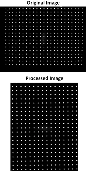
increasing the performance. Figure 3.3 shows an original image and the image after the
algorithm was applied. The results are very subtle, but it can be seen that the white dots
in the source image are not perfectly aligned and have a slight convex curve to them.
The processing works by moving and interpolating the pixels so these dots appear more
aligned. Normally, this algorithm takes a few seconds to process. When combined with
Original Image
[image:24.612.159.443.84.647.2]Processed Image
end user. Using SIMD instructions can be help increase the performance of this
algorithm.
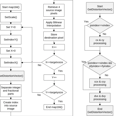
The main image processing occurs in two nested loops, which move over the entire
destination image as shown in Figure 3.4. The function map1bli begins by first setting
the scale of the image, and setting the x and y indices of the distortion matrix with the
SetIndexX and SetIndexY functions, respectively. This information is used by the
algorithm to determine which value from the distortion matrix must be used. Next, the
distortion vectors (dvx and dvy) are calculated in the GetDistortionVector function. The
vectors are based on the distortion matrix and the current pixel being processed in the
destination image. The function contains static variables (cx, cy, ccx, ccy), that don’t
change every time the function is called. At the end of the function, the variables pxindex
and pfyindex are set equal to xindex and fyindex, respectively. The new values of xindex
and fyindex are compared to the saved values, pxindex and pfyindex, as shown. If they
are equal, then the processing of the static variables is skipped to help increase the
performance. If they are not equal, then the static variables must be recalculated. These
variables are then used to calculate the distortion vectors, dvx and dvy. The vectors
contain an integer part in the 16 most significant bits and a fractional part in the 16 least
significant bits. The GetDistortionVector function returns the vectors to the map1bli
function.
The fractional and integer parts of the distortion vectors are separated, and the
integer part is used to determine the correct pixel from the source image. Next, the
values of this pixel and three surrounding pixels are retrieved from the source image.
Bilinear interpolation occurs between these pixels based on the fractional parts of the
distortion vectors, and the resulting value is saved to the destination image. The process
continues for all the pixels in the destination image. The color channels are processed
separately; therefore, the map1bli function is called three times to process the three
Start map1bli()
SetScale()
Set Y=0
SetIndexY()
Set X=0
SetIndexX()
GetDistortionVector()
Separate integer and fractional
parts
X==targetxsize
Y==targetysize
End map1bli()
Start GetDistortionVector()
X++
Y++ No
No
Yes
Yes
pxindex==xindex
cx & cy processing
pxindex==xindex && pfyindex==fyindex
ccx & ccy processing
dvx & dvy processing
End GetDistortionVector()
No
No Yes
Yes
Create index into source
image
Retrieve 4 source image
pixels
Apply Bilinear Interpolation
[image:26.612.118.514.79.476.2]Store destination pixel
Chapter 4
Experimental Procedure
The following sections describe the tests which were performed that utilized the NEON
SIMD instructions. Section 4.1 and Section 4.2 describes the tests related to the bilinear
interpolation algorithm and the distortion algorithm, respectively.
4.1 Bilinear Interpolation Tests
The bilinear interpolation algorithm has three test cases with each test performed over
five different interpolation factors, and with a source image of one million total pixels.
The NEON based code is written manually because the vectorizing compiler cannot find
any vectorizable loops. The first test case is the baseline, which is described in Section
3.3.1. Section 4.1.1 describes NEON1, which is the first test using the SIMD intrinsic
functions with parallel color channel processing. Section 4.1.2 describes NEON2, which
is the second test using the SIMD intrinsic functions with the processing of four pixels
concurrently.
4.1.1 NEON1 Test
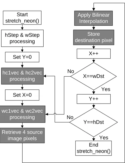
NEON1 is the first test case involving the NEON SIMD intrinsic functions. The code is
shown in Appendix C, and the program’s flow is shown in Figure 4.1 with the vectorized
parts in dark grey. This test processes all three color channels in parallel rather than
sequentially. A lane of the NEON registers is not used because the image has three
color channels, but four lanes in each register. All NEON variables use the 128-bit quad
registers which require variables that are either 16 bits and fill eight lanes or 32 bits and
fill four lanes.
This test starts by calculating the variables hc1 and hc2 without the use of SIMD
instructions. These variables are then duplicated into separate NEON registers,
referenced as hc1vec and hc2vec. The duplication instruction copies the value into each
of the eight lanes. The same process is done for the variables wc1 and wc2 which are
stored in NEON variables wc1vec and wc2vec, respectively. The image processing
begins by first retrieving the four pixels used for interpolation and storing them into
OffsetY, and the source image’s dimensions. The register layouts for the pixelavec and
pixelbvec variables are shown in Figure 4.2. Because pixel1 and pixel3 are stored
sequentially in memory, they are loaded with one instruction into a double NEON
register (64 bits). Next, the values are reinterpreted from two 32-bit values to eight 8-bit
values, and then extended to 16 bits. The extension fills the quad registers and allows
the image processing to occur on a width of 16 bits. The same process is done for
pixelbvec with the pixel2 and pixel4 variables, which are also stored sequentially in
memory. The builtin_prefetch function is used to preload the cache with the next likely
source data. The function’s first argument is the address of the expected data, the
second argument is set to zero for read/write access, and the third argument is set to
two for locality. The locality determines how long the data should stay in the cache. The
remaining image processing is similar to the baseline code except for the use of SIMD
intrinsic functions. Many of the shift and bitwise AND operations are not needed because
of how the NEON registers are set up. At the end, one double register contains the result
with four lanes of 16-bit values. The values are reduced to four lanes of 8-bit values and
stored in memory pointed to by the Dst variable. The Dst pointer is incremented, the
Start stretch_neon()
Set Y=0
hc1vec & hc2vec processing
Set X=0
X==wDst
Y==hDst
End stretch_neon()
X++
Y++ No
No
Yes
Yes Retrieve 4 source
image pixels
Apply Bilinear Interpolation
Store destination pixel hStep & wStep
processing
[image:28.612.195.403.73.343.2]wc1vec & wc2vec processing
coefficients are increased, and the process repeats in a loop through all the pixels in the
destination image.
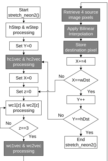
4.1.2 NEON2 Test
NEON2 is the second test case involving the NEON SIMD intrinsic functions. The code
is shown in Appendix D, and the program’s flow is shown in Figure 4.3 with the
vectorized parts in dark grey. This test processes four sequential pixels in parallel rather
than one at a time. As with the baseline, each color channel is processed separately.
The variables use the quad registers, and each pixel has a 32-bit lane. Unlike NEON1,
this setup does not waste lanes because four values are being processed concurrently
and four lanes are available for processing.
This test is very similar to the baseline except for the use of SIMD intrinsic functions.
The factors hc1 and hc2 are calculated using ARM instructions and copied into the four
32-bit lanes of hc1vec and hc2vec, respectively. The values for wc1 and wc2 change
with each x-loop iteration. The x-loop is the inner loop of the processing and defines the
x-coordinate for the destination pixel. Therefore, they are calculated as a four element
array in a loop, and a NEON instruction is used to load them from memory into the
128-bit registers. Each lane of the source image registers is set individually, because the
values loaded into the NEON registers may not appear sequentially in memory. The
interpolation part of the processing is accomplished in the same way as the baseline
code except four pixels are processed concurrently. The whole destination register is
pixelavec
C3 C2 C1 C3 C2 C1
Pixel3 Pixel1
Variable
Color Ch.
pixelbvec
C3 C2 C1 C3 C2 C1
Pixel4 Pixel2
Variable
Color Ch.
Unused lanes 16 bits
sent to memory pointed by Dst. The destination pointer is incremented by four during
each x-loop iteration and decremented at the end of the x-loop if the destination width is
not divisible by four. This allows the x-loop to overstep and return if the destination
image width is not divisible by four. This method does waste some processing time on
pixel values that are in the end discarded.
4.2 Distortion Tests
The distortion algorithm is run with twelve different test cases with each test using the
same input image of eight million pixels and three color channels, and a 23 by 17
distortion matrix with two dimensional vectors. The code was compiled with the
vectorizing compiler, but it could not find any vectorizable loops in the image processing
part of the code. Therefore, the SIMD instructions were inserted manually. The first test
is the baseline code as described in Section 3.3.2. The next four tests use the NEON
SIMD intrinsic functions, and are described in Section 4.2.1 through Section 4.2.4.
[image:30.612.202.411.73.383.2]Section 4.2.5 through Section 4.2.7 describes the three assembly based tests in which Figure 4.3: Bilinear Interpolation’s Program Flow for NEON2
X==wDst
Y==hDst
End stretch_neon2()
X+=4
Y++ No
No
Yes
Yes Retrieve 4 source
image pixels
Apply Bilinear Interpolation
Store destination pixel Start
stretch_neon2()
Set Y=0
hc1vec & hc2vec processing
Set X=0 hStep & wStep
processing
wc1vec & wc2vec processing
Set z=0
wc1[z] & wc2[z] processing
z==3 No
the assembly is altered with SIMD instructions and other techniques. The remaining
tests attempted additional ways to speed-up the execution of the algorithm. Section
4.2.8 explains the move from 32-bit operands to 16-bit operands. Section 4.2.9
discusses the test using both the integer and floating point functional units. Section
4.2.10 discusses using both the ARM processor and NEON coprocessor in parallel
during the image processing. Section 4.2.11 discusses enhancements at the assembly
level made to the baseline code without using NEON instructions.
4.2.1 NEON1 Test
This NEON1 test case applies NEON SIMD intrinsic functions to the main image
processing by computing four pixels per iteration instead of one pixel as shown in Figure
4.4 with the vectorized parts in dark grey. First, the GetDistortionVector function is
altered by including the SetIndexX function so an extra function call can be eliminated.
Second, because the GetDistortionVector function is a part of the code that cannot be
calculated easily in parallel with SIMD instructions, it is executed four consecutive times
using only ARM instructions. The result is saved to two 4-element C arrays, referenced
as dvx[] and dvy[], which are then loaded into NEON registers. Next, the fractional and
integer parts are separated and the index into the source image is created using parallel
operations with the NEON coprocessor. The index is saved as a vector to memory
Start GetDistortionVector()
Pxindex==xindex
cx & cy processing
Pxindex==xindex && pfyindex==fyindex
ccx & ccy processing
dvx[i] & dvy[i] processing End GetDistortionVector() No No Yes Yes Set i=0 i==3 Yes No i++ Start map1bli() SetScale() Set Y=0 SetIndexY() Set X=0 Separate integer and fractional parts X==targetxsize Y==targetysize End map1bli() X+=4 Y++ No No Yes Yes Create index into
source image
[image:31.612.94.510.77.311.2]Retrieve 4 source image pixels Apply Bilinear Interpolation Store destination pixel GetDistortionVector()
because the SIMD registers cannot be used as an index into memory. Saving the
vectors to memory avoids the 20 cycle stall when transferring from the NEON
coprocessor to the ARM processor. The ARM registers are loaded with the index from
memory, which is then used by the NEON coprocessor to load the source image data
into SIMD registers. Each NEON register lane is loaded individually from the source
image because the pixels may not occur sequentially in memory and therefore multiple
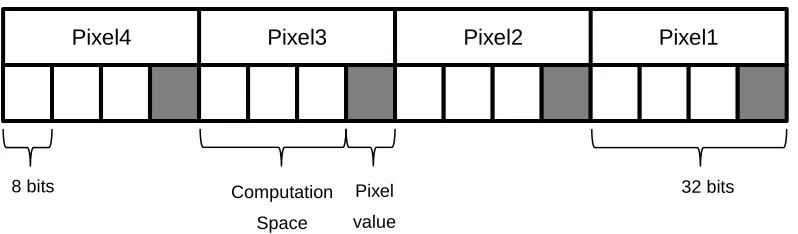
pixels cannot be loaded with one instruction. Figure 4.5 shows how the four pixels are
placed in a SIMD register. The pixels are 8-bit values, but they are loaded into 32-bit
lanes because the bilinear interpolation step requires 32 bits to perform the
computations. The bilinear interpolation of the four pixels occurs concurrently using the
source image’s values and the fractional parts of the distortion vector. Each lane is
saved individually to the destination image array. The destination array is incremented
and the loop repeats until the destination image has been processed.
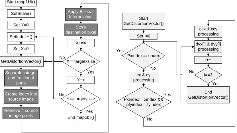
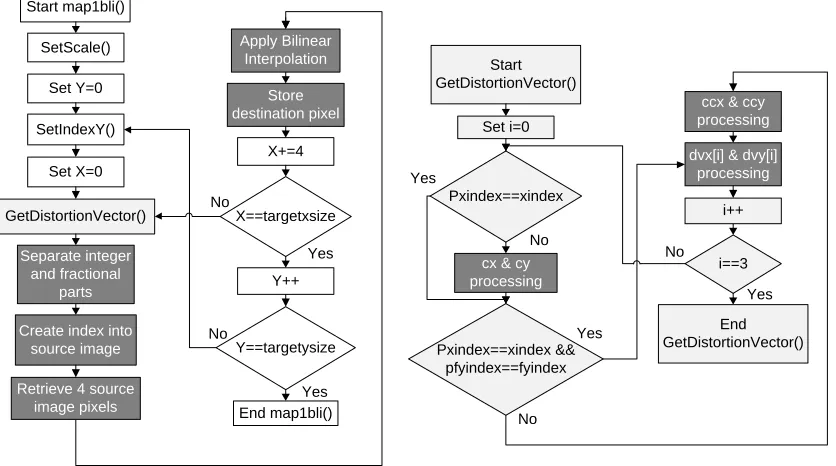
4.2.2 NEON2 Test
The NEON2 test case adds onto the NEON1 test case with vectorizing the calculations
in the GetDistortionVector function. The program flow for this test is shown in Figure 4.6
with the vectorized parts in dark grey. One way to accomplish the parallelizing is to
compute all four components of the distortion vectors, dvx[] and dvy[], in parallel rather
than in a loop. This requires removing the pfyindex and pxindex comparisons and
computing the static variables cx, cy, ccx, and ccy during every function call. These are
rarely recomputed (about once every 150 function calls) as recomputing them every
function call would likely increase the time this function takes to complete. This option
was not chosen for its likely performance decrease.
Pixel
[image:32.612.110.509.93.210.2]value
Figure 4.5: Distortion Algorithm’s SIMD Register Setup
8 bits
C C
C C
Pixel2 Pixel1
C C
C C
Pixel4 Pixel3
Computation
Space
Another option is to leave the current structure of the function, and parallelize the
computing of the cx, cy, ccx, and ccy variables and the distortion vectors. This option is
more difficult because those variables are not easily calculated in parallel. Also,
additional instructions are needed to ensure the data is in the correct lanes. The result of
this function is two distortion vectors that are contained in NEON registers. This
eliminated the need to load the vectors from memory to be processed. The main image
processing is identical to the NEON1 test. This option is chosen because it does not
recompute the static variables and thus should have increased performance.
4.2.3 NEON3 Test
The NEON3 test case adds onto the NEON1 test case with minor rearranging of the
code. Figure 4.7 shows the program flow for this test with the vectorized parts shown in
dark grey. The GetDistortionVector function was moved to before the start of the inner
x-loop and to the middle of image processing. The former is needed for the first run of the
x-loop, and the latter will precompute the distortion vectors for the next iteration of the
loop. However, the precomputation does not occur during the last iteration of the x-loop
because the precomputation is not needed. The rearranging attempts to operate the
ARM and NEON processors more concurrently, and help decrease the amount of stalls
due to data dependencies. Because GetDistortionVector() uses mostly the ARM
Start GetDistortionVector()
Pxindex==xindex
cx & cy processing
Pxindex==xindex && pfyindex==fyindex
ccx & ccy processing
dvx[i] & dvy[i] processing End GetDistortionVector() No No Yes Yes Set i=0 i==3 Yes No i++ Start map1bli() SetScale() Set Y=0 SetIndexY() Set X=0 Separate integer and fractional parts X==targetxsize Y==targetysize End map1bli() X+=4 Y++ No No Yes Yes Create index into
source image
[image:33.612.93.511.77.310.2]Retrieve 4 source image pixels Apply Bilinear Interpolation Store destination pixel GetDistortionVector()
processor and the image processing uses mostly the NEON coprocessor, placing this
function in the middle of the image processing should allow the processors to act more
in parallel.
4.2.4 NEON4 Test
The NEON4 test case adds onto the NEON3 test case with the use of the compiler’s
“hint” functions. The cache “hint” function is used to prefetch the expected source and
destination images for the next iteration of the x-loop. The builtin_prefetch function is
implemented with the expected next address of the source or destination pixels as the
first argument. The second argument is set to zero for the read only source image and
set to one for the write to the destination image. The third argument is set to two to leave
the data in the cache as long as possible. The “hint” function for the branch prediction is
used when calling the GetDistortionVector function within the image processing part of
the code. This is accomplished with the builtin_expect function, which uses the
comparison expression as the first argument, and the expected result of the comparison
as the second argument. Because the GetDistortionVector function is called every x-loop
iteration except for the last, it can be expected that the branch will always be true.
Therefore the second argument is set to one which tells the compiler the branch is
usually taken.
Start GetDistortionVector()
Pxindex==xindex
cx & cy processing
Pxindex==xindex && pfyindex==fyindex
ccx & ccy processing
dvx[i] & dvy[i] processing End GetDistortionVector() No No Yes Yes Set i=0 i==3 Yes No i++ Start map1bli() SetScale() Set Y=0 SetIndexY() Set X=0 Separate integer and fractional parts X==targetxsize Y==targetysize End map1bli() X+=4 Y++ No No Yes Yes Create index into
source image
[image:34.612.95.508.78.321.2]Retrieve 4 source image pixels Apply Bilinear Interpolation Store destination pixel GetDistortionVector() GetDistortionVector()
4.2.5 ASM1 Test
The ASM1 test case starts with the assembly code from the NEON4 case. Figure 4.8
shows the program flow for this test with the NEON vectorized parts shown in dark grey.
The compiler performed a few optimizations with the code. First, it inlined the
GetDistortionVector function both before the x-loop (shown as GetDistortionVector) and
in the middle of image processing (shown as GetDistortionVector_prefetch). Inlining
functions decreases the number of branches, which can decrease the branch
mispredictions. Second, the i-loops in both of these functions are unrolled by four and a
few unneeded branches are eliminated. This should help reduce the number of program
counter changes and possibly the number of branch mispredictions. The compiler
builtin_prefetch function is compiled into an assembly PLD instruction. This instruction
signals to the memory system that a data load from the specified address is likely. The
compiler builtin_expect function did not compile into an assembly instruction and there is
no evidence that this function is implemented.
Using the compiler’s assembly code, this test removes one branch and some
unneeded loads from and stores to memory. The first change removes the equality
check for pfyindex and fyindex. The fyindex variable only changes after the SetIndexY
function is called, and the pfyindex variable is set equal to fyindex after the distortion
vectors are computed. Therefore, the GetDistortionVector function always initially
processes cx, cy, ccx, and ccy because it is after the SetIndexY function. In the
GetDistortionVector_prefetch function, the equality check for fyindex and pfyindex is not
needed because they will always be equal. The second change involves altering how the
program stores static variables used by the distortion vector functions. The compiler
handles the variables by storing their address, instead of the actual value, to the stack.
To access these variables, the address must first be loaded from the stack and then the
value can be loaded or stored based upon that address. This was changed to save or
load the value directly to or from the stack which eliminated a load for each of the static
variables. The third change altered the calculations of the cx, cy, ccx, and ccy variables.
The compiler does not fully utilize the ARM registers and therefore intermediate values
are stored to memory rather than kept in registers. The code is rearranged and registers
changes such that the intermediate values were rarely stored to memory, which
eliminated many load and stores instructions.
The NEON SIMD code has a few modifications as well. One modification helps to
Start GetDistortionVector()
cx & cy processing
ccx & ccy processing
End GetDistortionVector()
Pxindex==xindex cx & cy processing
ccx & ccy processing
Pxindex==xindex
cx & cy processing
ccx & ccy processing
No
Yes Pxindex==xindex cx & cy
processing
ccx & ccy processing
dvx[] & dvy[] processing No Yes No Yes Start GetDistortionVector _prefetch()
cx & cy processing
ccx & ccy processing End GetDistortionVector _prefetch() Pxindex==xindex Pxindex==xindex
cx & cy processing
ccx & ccy processing
No
Yes Pxindex==xindex cx & cy
processing
ccx & ccy processing
dvx[] & dvy[] processing No
Yes No
Yes cx & cy
processing
ccx & ccy processing Pxindex==xindex No Yes Start map1bli() SetScale() Set Y=0 SetIndexY() Set X=0 Separate integer and fractional parts X==targetxsize Y==targetysize End map1bli() X+=4 Y++ No No Yes Yes Create index into
source image
[image:36.612.139.470.68.681.2]Retrieve 4 source image pixels Apply Bilinear Interpolation Store destination pixel GetDistortionVector() GetDistortionVector _prefetch()
values in the image processing do not change with each loop iteration. Intially, these
values are loaded from memory or computed during each loop iteration as needed. This
test case keeps the constant variables in the NEON registers. This change makes
processing the image more difficult because there are less registers available to keep
data. Another change exploits the option of dual issuing instructions. The NEON and
ARM processors can issue two instructions at a time if one instruction is a load or store
and no dependencies exist. The compiler attempts to accomplish this, but manually
altering the code exploits this possibility even more. The code is modified to put load and
store instructions near other instructions and to remove data dependencies between
instructions.
4.2.6 ASM2 Test
The ASM2 test case uses the assembly from the ASM1 test, and vectorizes the
calculation of the distortion vectors, dvx and dvy, in both the GetDistortionVector and
GetDistortionVector_prefetch functions. Figure 4.9 shows the program flow for this test
with the NEON vectorized parts shown in dark grey. The static variables ccx and ccy
used for this calculation are either calculated with ARM instructions and transferred to
NEON registers, or loaded from memory into NEON registers. The distortion vectors are
then calculated based on these variables, and kept in NEON registers until they are
separated into their integer and fractional parts in the image processing part of the code.
This saves an extra store from ARM to memory and load from memory to NEON, and
processes the vectors in parallel. The image processing part of the code is identical to
the ASM1 test.
4.2.7 ASM3 Test
This final assembly test builds on the ASM2 test, but processes eight pixels instead of
four pixels per iteration. In previous tests, the NEON registers were not fully utilized
during the image processing. These extra registers are now used to process twice the
number of pixels per iteration which can increase performance. Calculating more pixels
can help limit the data dependency stalls between the instructions and reduce the
number of branches. Stalls from structural dependencies may arise, but because the
NEON functional units are pipelined, the effect should be minimal. The calculation of
distortion vectors are unrolled by a factor of eight to correspond with the eight pixels
Start GetDistortionVector()
cx & cy processing
ccx & ccy processing
End GetDistortionVector()
Pxindex==xindex cx & cy processing
ccx & ccy processing
Pxindex==xindex
cx & cy processing
ccx & ccy processing
No
Yes Pxindex==xindex cx & cy
processing
ccx & ccy processing
dvxvec & dvyvec processing No Yes No Yes Start GetDistortionVector _prefetch()
cx & cy processing
ccx & ccy processing End GetDistortionVector _prefetch() Pxindex==xindex Pxindex==xindex
cx & cy processing
ccx & ccy processing
No
Yes Pxindex==xindex cx & cy
processing
ccx & ccy processing
dvxvec & dvyvec processing No
Yes No
Yes cx & cy
processing
ccx & ccy processing Pxindex==xindex No Yes Start map1bli() SetScale() Set Y=0 SetIndexY() Set X=0 Separate integer and fractional parts X==targetxsize Y==targetysize End map1bli() X+=4 Y++ No No Yes Yes Create index into
source image
[image:38.612.142.473.56.656.2]Retrieve 4 source image pixels Apply Bilinear Interpolation Store destination pixel GetDistortionVector() GetDistortionVector _prefetch()
preloading the cache has on the performance. Although the preload instruction could
minimize cache misses, the instruction does take time to execute.
4.2.8 32-bit to 16-bit test
This test takes the baseline code and alters it by using 16-bit operands instead of 32-bit
operands with non-SIMD code. For the distortion vectors, the 16-bit operands require
changing from 16-bit integer and fractional parts to 8-bit parts. The rest of the image
processing occurs with 16 bit values. Truncating and rounding will be likely during the
multiplication and addition of variables. Using 16 bits doubles the amount pixels that can
be in a NEON register which should increase performance. However, losing half the
precision could cause undesirable errors in the destination image.
4.2.9 Integer and Floating Point Test
This test uses the integer and floating point functional units of the NEON coprocessor in
parallel. The NEON coprocessor has an integer ALU, multiplier, and shifter and a
floating point adder and multiplier. The test uses the NEON intrinsic functions, with
integer and floating point data types, and processes four pixels using integer calculations
in parallel with four pixels using floating point calculations. The only portion of the code
tested is the bilinear interpolation in the image processing, but the test could be
expanded to the rest of the code. The source pixels and distortion vectors are converted
to floating point numbers and stored in NEON registers. The code has shift left
operations which are not able to be processed with the floating point functional units. So
instead of shifting left, the floating point numbers are multiplied by a power of two
corresponding to the shift. A shift right operation is also present in the algorithm.
Because a floating point shifter or divider are not available, the shift right is
accomplished in the integer part of the coprocessor. The conversion between integer
and floating point numbers takes two cycles to complete for the NEON coprocessor. The
initial conversion and converting for shift right instructions will likely cause an increase in
the number of cycles and therefore decreased performance. The test uses single
precision floating point numbers which reserve 23 bits for the fractional part. Moving
from 32-bit operations to 23-bit operations may produce errors in the destination image
due to the truncation of values. The added cycles along with image errors may cause
4.2.10
ARM and NEON Test
This test uses the NEON4 test case, and adds the processing of one pixel per iteration
with the ARM processor to the four pixels per iteration with the NEON coprocessor. The
ARM and NEON coprocessors can run in parallel and this test attempts to exploit this
feature. First, the loop in the GetDistortionVector function is changed to produce five
value dvx and dvy distortion vectors. Four values are used for SIMD and one value is
used for ARM processing. Processing five pixels per iteration should cause a small
increase in performance because structural hazards will not be present between the
ARM and NEON pipeline. However, the ARM and NEON coprocessors will have to
access the same cache block which could cause some stalls due to ordering issues.
This test could also be expanded to ten pixels per iteration wi
![Figure 2.2: ARM and NEON Pipeline for the Cortex-A8 [4]](https://thumb-us.123doks.com/thumbv2/123dok_us/49140.4467/14.612.113.512.84.370/figure-arm-neon-pipeline-cortex-a.webp)