Managing light in engineered nonlinear
optical structures
Xin Chen
November 2017
A THESIS SUBMITTED FOR THE DEGREE OF
DOCTOR OF PHILOSOPHY
OF THE AUSTRALIAN NATIONAL UNIVERSITY
Department of Laser Physics Centre
Research School of Physics and Engineering
College of Physical and Mathematical Sciences
The Australian National University
iii
Declaration
This thesis reports the research I conducted during 2013 and 2017, at the Department of Laser Physics Centre, the Australian National University, Canberra, Australia.
To the best of my knowledge, the material reported here is original except where acknowledged and reference in appropriate manner. It has not been previously published by others, or submitted in whole or in part for any university degrees.
v
Acknowledgement
I would like to express my most sincere gratitude to all the people who directly and indirectly helped me during my PhD study.
First of all, I would like to thank to my supervisory panel: Professor Wieslaw Krolikowski, Dr. Yan Sheng, and Dr. Vladlen Shvedov. It is my great honour to be a student of Professor Wieslaw Krolikowski. His broad knowledge, deep insights and scientific visions are always inspirational. Every time I talk to him I can learn something new and get much useful advice on my work. I would also like to thank him for supporting my attendance to those conferences and the research travel to Texas A&M University at Qatar. My special thanks go to Dr. Yan Sheng, who is always inspiring and encouraging me, especially when I get stuck in experiment. Thanks to Dr. Vladlen Shvedov for useful discussions on my projects.
vi
Xinyu Yang, Dr. Tong Wang, Dr. Wenguo Zhu, Dr. Siwei Xu, Dr. Fajun Li, Dr. Jun Cheng and Mr Haijie Zuo, and this list goes on and on. To LPC department administrator Ms. Sonia Padrun, RSPE HDR administrator Ms. Liudmila Mangos and Ms. Karen Nulty, Centre for Plasmas and Fluids Plasma Research Laboratory administrator Ms. Uyen Nguyen and Mrs. Susie Radovanovic, for their great efforts to handle students’ administrative work.
None of my projects can go forward without the essential equipment and technical support from Centre for Advanced Microscopy (CAM). Thanks to Mr. Daryl Webb, who offered me enormous help in using and analyzing results from confocal microscopy. Otherwise my projects cannot proceed smoothly. Thanks to Dr. Hua Chen for his help on SEM measurement. Thanks to CAM administrator Ms. Josie Smith, for her kind assistance in getting my access to the facilities in CAM.
During my PhD study, Professor Wieslaw Krolikowski offered me an opportunity to visit his research group in the Science Program at Texas A&M University at Qatar. It was a very eye-opening experience for me. I worked there for four weeks, Professor Wieslaw Krolikowski and Dr. Krzysztof Świtkowski provided me continuing guidance in laboratory and also great help in life in Doha.
My friends in Australia deserve a special acknowledgement. To Mr. Naiyin Wang, Mr. Zhe Li, Ms. Na Yu, Ms. Kunrong Yang, Mr. David Lockwood, Dr. Fenglin Xian, Dr. Yujie Ma, Mr. Peng He, Dr. Weizong Xu, Dr. Guogang Zhang and Mr. Rongping Tang. Doing a PhD abroad is hard, but all these nice friends and peers make my life in Canberra much easier.
I acknowledge the financial support of the China Scholarship Council and Australian National University (ANU) Tuition Fee Scholarship, which made my study at ANU possible.
ix
Abstract
Optical frequency conversion process allows one to generate coherent light in wavelength ranges that are not readily available. It is well known that because of dispersion, the phase mismatch between interacting waves leads to low efficiency of frequency generation. Quasi-phase matching (QPM) that uses crystals with a spatial modulation of the second-order nonlinear coefficient χ(2), also known as nonlinear photonic crystals (NPC), is an important technique to solve the phase mismatch problem. With proper design of the quadratic nonlinearity modulation, one can not only obtain efficient frequency conversion, but also make diverse applications possible, including beam and pulse shaping, all-optical processing, entangled photon generation and manipulation.
This thesis explores the fabrication, properties and application of various types of NPCs. In particular, we discuss NPC fabricated in single-domain ferroelectric crystals by using all-optical poling with near infrared femtosecond laser pulses and high voltage electric poling; as grown ferroelectric crystals with random sized ferroelectric domains; and orientation patterned semiconductors grown by hydride vapour phase epitaxy. Specifically, this research work involved the following topics:
1. Systematic investigation of a novel technique of direct writing of ferroelectric domains using near-infrared femtosecond laser pulses. Domain inversion in a LiNbO3 crystal was realized by its illumination
x
a QPM structure in a LiNbO3 channel waveguide was fabricated by
this infrared laser poling technique allowing efficient frequency doubling of 815 nm light beam.
2. Experimental studies of the application of as-grown calcium barium niobate (CBN) crystal for a broadband frequency conversion. This frequency conversion process is similar to broadband harmonic generation in commonly used strontium barium niobate (SBN) crystal, but results in higher conversion efficiency reflecting a larger effective nonlinear coefficient of the CBN crystal. We also analyzed the spatial distribution of the intensity of the generated radiation as well as its polarization properties. This study contributes to a simpler and more efficient realization of broadband frequency conversion devices in a wide class of nonlinear optical media.
3. Experimental studies of multistep cascading frequency conversion processes in a custom-cut periodically poled lithium niobate crystal. By employing the total internal reflection inside the sample, we combined quasi-phase matched collinear and Cerenkov nonlinear sum frequency mixing to achieve enhanced fourth harmonic generation in a single periodically poled lithium niobate crystal.
xi
Publications
Journal articles
[1] Xin Chen, Pawel Karpinski, Vladlen Shvedov, Kaloian Koynov, Bingxia Wang, Jose Trull, Crina Cojocaru, Wieslaw Krolikowski, and Yan Sheng. Ferroelectric domain engineering by focused infrared femtosecond pulses. Applied Physics Letters, Vol. 107, Iss. 14, pp. 141102, 2015.
[2] Xin Chen, Pawel Karpinski, Vladlen Shvedov, Andreas Boes, Arnan Mitchell, Wieslaw Krolikowski, and Yan Sheng. Quasi-phase matching via femtosecond laser induced domain inversion in lithium niobate waveguides. Optics Letters, Vol. 41, No. 11, pp. 2410-2413, 2016.
[3] Xin Chen, Krzysztof Switkowski, Xiaopeng Hu, Wieslaw Krolikowski, and Yan Sheng. Enhanced fourth harmonic generation via nonlinear Cerenkov interaction in periodically poled lithium niobate crystal. Optics Express, Vol. 24, No. 26, pp.29948-29954, 2016.
[4] X. Chen, V. Shvedov, P. Karpinski, K. Koynov, A. Boes, A. Mitchell, J. Trull, C. Cojocaru, W. Krolikowski, and Y. Sheng. Ferroelectric domain patterning with ultrafast light. Optics & Photonics News, Vol. 27, special issue: Optics in 2016, pp.50, 2016.
[5] Xin Chen, Pawel Karpinski, Vladlen Shvedov, Bingxia Wang, Jose Trull, Crina Cojocaru, Andreas Boes, Arnan Mitchell, Wieslaw Krolikowski, and Yan Sheng. Two-dimensional domain structures in Lithium Niobate via domain inversion with ultrafast light. Photonics Letters of Poland, Vol. 8, No. 2, pp. 33-35, 2016.
xii
[7] Pawel Karpinski, Xin Chen, Vladlen Shvedov, Cyril Hnatovsky, Arnaud Grisard, Eric Lallier, Barry Luther-Davies, Wieslaw Krolikowski, and Yan Sheng, “Nonlinear diffraction in orientation-patterned semiconductors”, Optics Express, Vol.23, No. 11, pp. 14903-14912, 2015.
[8] Vladlen Shvedov, Pawel Karpinski, Yan Sheng, Xin Chen, Wenguo Zhu, Wieslaw Krolikowski, and Cyril Hnatovsky. Visualizing polarization singularities in Bessel-Poincaré beams. Optics Express, Vol. 23, No. 9, pp. 12444-12453, 2015.
Conference papers
[1] Xin Chen, Pawel Karpinski, Vladlen Shvedov, Kaloian Koynov, Bingxia Wang, Jose Trull, Crina Cojocaru, Wieslaw Krolikowski, and Yan Sheng. Direct writing of inverted domains in lithium niobate using infrared femtosecond pulses. International Conference on Nanoscience and Nanotechnology (ICONN), 2016.
[2] Xin Chen, Pawel Karpinski, Vladlen Shvedov, Cyril Hnatovsky, Andreas Boes, Arnan Mitchell, Wieslaw Krolikowski, and Yan Sheng. Direct writing of inverted domain patterns in lithium niobate waveguides using femtosecond infrared pulses. Conference on Lasers and Electro-Optics (CLEO): Applications and Technology, paper ATu4K.4, 2016.
[3] Xin Chen, Pawel Karpinski, Vladlen Shvedov, Cyril Hnatovsky, Andreas Boes, Arnan Mitchell, Wieslaw Krolikowski, and Yan Sheng. Ferroelectric domain engineering using infrared femtosecond laser and its application to optical frequency conversion. Photonics and Fiber Technology, paper NM3A.6, 2016 (invited talk).
[4] Xin Chen, Wieslaw Krolikowski, and Yan Sheng. Ultrafast-laser-inscribed nonlinear photonic crystals for frequency conversion. Collaborative Conference on Materials Research (CCMR), 2017.
xiii
xiv
Acronyms and Symbols
ACAFM BaNb2O6 BaTiO3 BN BPM CBN CLN CSHG CSHM CW DFG EFP Er: YAG FB FHG GaAs GaN GaP HF HNO3 HVPE InGaAs IR KDP KTA Alternating current Atomic force microscopy Barium niobate
Barium titanate Barium niobate
Birefringent phase matching Calcium barium niobate Congruent lithium niobate
Cerenkov second harmonic generation Cerenkov second harmonic microscopy Continuous wave
Difference frequency generation Electric field poling
Erbium-doped yttrium aluminium garnet laser
Fundamental beam
Fourth harmonic generation Gallium arsenide
Gallium nitride Gallium phosphide Hydrofluoric acid Hydrogen nitrate
Hydride vapour phase epitaxy Indium gallium arsenide Infrared
xv KTiOAsO4 LAP LiNbO3 LiTaO3 LN MgO: LN NA NLD NPC OP OPA OP-GaAs OPO PFM PI PPLN QCL QPM QPOS RbTiOPO4 RLV RTP SBN SFM SHG SN SNDM SrNb2O6
Potassium titanyl arsenate Light assisted poling Lithium niobate Lithium tantalate Lithium niobate
Magnesium-doped lithium niobate Numerical aperture
Nonlinear diffraction
Nonlinear photonics crystals Orientation patterned
Optical parametric amplifiers
Orientation patterned gallium arsenide Optical parametric oscillators
Piezoresponse force microscopy Poling inhibition
Perodically poled lithium niobate Quantum cascade laser
Quasi-phase matching
Quasi-periodic optical supperlattice Rubidium titanyl phosphate
Reciprocal lattice vector Rubidium titanyl phosphate Strontium barium niobate Sum frequency mixing Second harmonic generation Strontium niobate
xvi SVEA
TEM THG TTB
Slowly varying envelope approximation Transmission electron microscopy Third harmonic generation
Tetragonal tungsten bronze
UV Ultra-violet
xvii
Table of Contents
Declaration ... iii
Acknowledgement ... v
Abstract ... ix
Publications ... xi
Acronyms and Symbols ... xiii
List of Figures ... xix
List of Tables ... xxiii
Chapter 1 Introduction ... 1
1.1 Laser and nonlinear optics ... 1
1.2 Nonlinear wave equation ... 2
1.3 Phase matching condition ... 5
1. 4 Methods of phase matching ... 11
1.4.1 Birefringent phase matching ... 11
1.4.2 Quasi-phase matching ... 15
1.5 Noncollinear second harmonic generation ... 19
1.6 Motivation and thesis arrangement ... 22
Chapter 2 Fundamental aspects of nonlinear optics in quadratic media ... 24
2.1 Introduction ... 24
2.2 QPM materials ... 25
2.2.1 Domain engineering in ferroelectrics ... 25
2.2.2 Orientation patterned semiconductors ... 30
2.3 Versatile QPM structures ... 32
xviii
2.4.1 Electric field poling ...37
2.4.2 UV poling ...39
2.4.3 Other poling techniques ...46
2.5 Domain visualization ...47
2.5.1 Chemical etching ...47
2.5.2 Piezoresponse force microscopy ...49
2.5.3 Cerenkov second harmonic microscopy ...50
2.6 Summary ...54
Chapter 3 All optical poling using IR femtosecond laser pulses ... 56
3.1 Introduction ...56
3.2 Experimental setup ...57
3.4 Domain engineering using ultra short pulses ...59
3.5 All optical poled QPM structure ...67
3.6 Summary ...73
Chapter 4 Broadband optical frequency conversion using Calcium Barium Niobate crystals ... 75
4.1 Introduction ...75
4.2 Experimental setup ...76
4.3 Experimental results ...77
4.4 Summary ...81
Chapter 5 Enhanced fourth harmonic generation in periodically poled lithium niobate ... 83
5.1 Introduction ...83
5.2 Experimental design ...84
5.3 Results and discussion ...88
xix
Chapter 6 Nonlinear diffraction in orientation patterned
Gallium Arsenide ... 93
6.1 Introduction ... 93
6.2 Experimental setup ... 96
6.3 Results and discussion ... 98
6.4 Summary ... 104
Chapter 7 Conclusions and outlook ... 105
7.1 Outcomes ... 105
7.2 Outlook and future work ... 107
xx
List of Figures
Figure 1.1 Typical (a) linear and (b) nonlinear polarization versus electric field curves. ... 4 Figure 1.2 Periodic oscillation of phase mismatched SHG along the
propagation direction. ... 9 Figure 1.3 Dependence of phase mismatched SHG as a function of
propagation distance in a thick quartz platelet [16]. ... 10 Figure 1.4 Dependence of phase mismatched SH intensity as a function
of propagation distance in a thick quartz platelet. ... 10 Figure 1.5 (a) Birefringent phase matching diagram in LiNbO3. (b)
Refractive index curves for the ordinarily and extraordinarily polarized beam in LiNbO3 [17]. ... 12
Figure 1.6 Intensity of SHG as a function of propagation distance in phase mismatched (curve A), QPM (curve B) and the exact phase matched (curve C) condition [12]. ... 16 Figure 1. 7 Collinear and noncollinear SHGs in a one dimensional
nonlinear medium. The red arrows and green arrows indicate the wave vectors of the FB and SHGs. The green dots on the black background represent the far field of noncollinearly emitted second harmonic beams recorded by a CCD camera. ... 20 Figure 1. 8 Phase matching diagrams for (a) nonlinear Bragg diffraction,
(b) nonlinear Raman-Nath diffraction and (c) nonlinear Cerenkov diffraction. ... 21
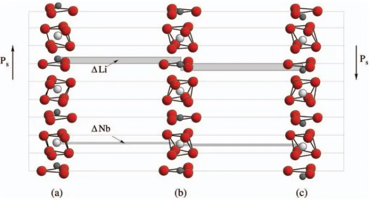
Figure 2. 1 A stack of thin plates of nonlinear medium periodically rotated by 180° to realize QPM [12]. ... 25 Figure 2. 2 Schematic of the structure of LiNbO3 in the (a) and (c)
xxi
displacement of the Li ions (in gray) from the oxygen (in red) planes, whereas ∆Nb stands for the displacement of the Nb atoms (in white) from their positions in the paraelectric phase. Both displacements occur along the crystal c-axis. Selected from reference [46]. ... 26 Figure 2. 3 A 10 mm thick MgO: PPLN crystal with QPM period of 32.2
μm [59]. ... 28 Figure 2. 4 Schematic diagram for reciprocal lattice vectors (represented
by white arrows) in a randomly distributed domain structure. (b) Random domain structures in the x-y plane of a SBN crystal visualized after chemical etching [71]. ... 29 Figure 2. 5 (a) Multigrating QPM structure for OPO. By translating the
crystal, the pump beam interacts with different grating sections. (b) A PPLN crystal with the fan-out domain pattern. The poling directions are indicated by the arrows on the side of the crystal [104, 105]. ... 32 Figure 2. 6 Illustration of a typical QPOS. (a) Two building blocks A
and B, each composed of ferroelectric domains with opposite directions, which are indicated by arrows. (b) A QPOS composed of two blocks arranged in Fibonacci sequence. The polarization of the FB is parallel to the z axis of the crystal in the THG process. (c) QPOS domain structures of a single LiTaO3 crystal visualized after
chemical etching. (d) Phase matching diagrams of the process of THG in a QPOS, which has two specially designed reciprocal vectors to compensate both mismatches in the SHG and SFG processes. Images selected from reference [108]. ... 34 Figure 2. 7 Image of a 2D PPLN with a period of 18.05 μm and the first
Brillouin zone [113]. ... 35 Figure 2. 8 Images of some quasi periodic and disordered 2D NPCs. (a)
xxii
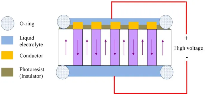
Microscope image and (c) theoretical design of a NPC designed based on the concept of binary nonlinear holograms. (d-g) Family of radial photonic structures. The domains with opposite directions are denoted by black and white areas, respectively. ... 35 Figure 2. 9 A typical setup for electric field poling of ferroelectric
crystals. Under the applied electric field will be reversed those domains below the patterned electrodes (conductor). The arrows indicate the directions of the spontaneous polarization after the poling process. ... 38 Figure 2. 10 SEM images of (a) a PI domain crossing obtained by two
subsequent laser tracks and (b) two PI line domains with a submicron gap. Replotted from reference [143]. ... 40 Figure 2. 11 SEM images of laser induced domain patterns on the -z
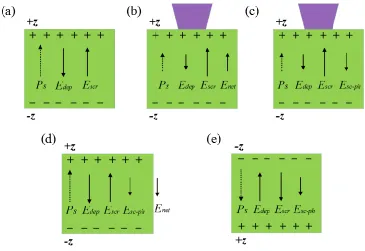
surface of an etched undoped CLN crystal written with different incident powers. Replotted from Replotted from reference [144]. 40 Figure 2. 12 Schematic of mechanism for domain inversion using CW
UV laser beam. (a) Equilibrium state before laser irradiation. (b) Laser induced heat reduces Ps and Edep, creating a net field Enet. (c)
Charges separation produces Esc-ph. (d) When cool, Ps and Edep
increase, creating a net field anti-parallel to Ps. (e) If Esc-ph>Ec, then
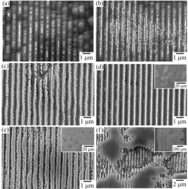
domain inverts. Replotted from reference [144]. ... 42 Figure 2. 13 SEM images of UV laser induced domain patterns using a
248nm laser beam with different intensities (a) 340, (b) 370, (c) 400, (d) 430, (e) 460 and (f) 490 mJ/cm2. A phase mask was used to form periodic domain patterns, which were revealed by HF acid etching. Replotted from reference [148]. ... 43 Figure 2. 14 SEM images of the +z face of undoped CLN crystals after
xxiii
Figure 2. 15 Schematic of chemical etching of z-cut PPLN, viewed in cross section. The arrows stand for the direction of the domains (spontaneous polarization). ... 48 Figure 2. 16 Schematic setup for PFM. The arrow in each of the domain
stands for the direction of the spontaneous polarization. ... 50 Figure 2. 17 Schematic of the CSHM. CSHG (a) can be detected when
illuminating a domain wall and (b) is absent when illuminating inside a domain. ... 51 Figure 2. 18 Domain structures imaged by CSHM. (a) Congruent
LiNbO3 with 2D short-range ordered domain structure. (b)
KTiOPO4 with 1D periodic domain structure. As-grown SBN
crystal at (c) x-y and (d) x-z planes, respectively. Images from reference [168]. ... 52 Figure 2. 19 (a) Three dimensional images of structures inside a CLN
crystal recorded by CSHM. (b) Transformation of an initially circularly shaped domain to hexagonally shaped (c) Formation of an irregular shaped domain due to the small defect in the domain pattern. (d) A merging process of two initially separated domains. Images from reference [168]. ... 52 Figure 2. 20 Three dimensional images recorded by CSHM during the
poling process of a z-cut SBN crystal. (a) Background signal for 0 kV/cm. (b-e) Growth process of domains with increasing electric field. Replotted from reference [169]. ... 54
xxiv
second harmonic signal, a conical Cerenkov signal is generated when a ferroelectric domain wall is produced. ... 57 Figure 3. 2 HF etched domain patterns written with (a) NA 0.2 and pulse
energy 9 nJ, (b) NA 0.3 and pulse energy 9 nJ, and (c) NA 0.65 and pulse energy 4 nJ. (d) Damages produced with NA 0.65 and pulse energy 5 nJ. ... 60 Figure 3. 3 Scanning electron microscopy images of square two-dimensional ferroelectric domain patterns (after HF etching) formed by infrared femtosecond laser optical poling. The period of the patterns is equal to (a) 2, (b) 1.5, and (c) 1 μm. ... 61 Figure 3. 4 Optical microscopic images of two-dimensional ferroelectric
domain patterns (after HF etching) formed by femtosecond optical poling. (a) Square lattice; (b) hexagonal lattice; (c) decagonal quasi-periodic; and (d) short-range ordered domain structures. .... 61 Figure 3. 5 Images of a square pattern of inverted domains in a lithium
niobate crystal obtained (a) using optical microscopy of HF-etched samples and (b) Cerenkov second harmonic microscopy. ... 64 Figure 3. 6 Three-dimensional visualisation of a section of square
pattern of inverted domains by Cerenkov second harmonic microscopy. (a) The first 15μm deep layer of the pattern (seen from the -z surface) illustrating good quality of the inverted domains. (b) Degradation of the domains structure at greater depths inside the crystal. ... 64 Figure 3. 7 Focusing of a plane wave laser beam through an interface of
air and a LiNbO3 crystal. O is the geometrical focus, while O1 and
O2 are the aberrated focuses. ... 65 Figure 3. 8 Focus splitting in z cut LiNbO3 crystal. (a) Writing
amorphous regions, also known as voxels, along z direction of a LiNbO3 crystal. Focus depth ranges from 5 to 50 μm. (b) Confocal
xxv
resemble the corresponding intensity distributions in the focal region. Replotted from reference [185]. ... 66 Figure 3. 9 Schematic of direct writing of ferroelectric domain patterns
in a Ti:in-diffused LiNbO3 channel waveguide using femtosecond
infrared pulses. ... 68 Figure 3. 10 Optical microscopic image of the 2-D optically poled
domain pattern with the period of 2.74 μm in the x direction and 1.15 μm in the y direction. Individual inverted domains are visible as small circles. Waveguide boundaries are indicated with dashed lines. (b) Three-dimensional profiles of the inverted domains obtained by the Cerenkov second-harmonic microscopy. ... 69 Figure 3. 11 Output intensity distribution of (a) the fundamental and (b)
the second-harmonic waves in the far field. The coordinate system is that of the LiNbO3 crystal. ... 70
Figure 3. 12 Wavelength tuning response of the second-harmonic generation in an optically poled LiNbO3 waveguide. The squares
depict experimental results, while the narrow curve represents theoretical tuning curve of 10 mm long ideal periodic structure for a continuous wave case. ... 71 Figure 3. 13 (a) Average power and (b) conversion efficiency of second
harmonic versus the average power of a fundamental wave at the optimal quasi-phase matching temperature 62.5 °C. The black squares and red dots represent the results of quasi-phase matched and pure waveguides without poling, respectively. The inset depicts details of SHG in the latter case. ... 72
Figure 4. 1 Image of the random ferroelectric domain pattern in the xz
xxvi
random CBN crystal. The grey disk represents the continuous distribution of reciprocal vectors in the crystal. Reciprocal vectors
G1 and G01 phase match the collinear and noncollinear SHG,
respectively. k1 and k2 represent the wave vectors of the
fundamental and SH waves, respectively. ... 78 Figure 4. 2 (a) Wavelength tuning curve of the SHG in the CBN-28
crystal for a constant input power of 2.0 mW. (b) Power of the SHG as a function of the average power of the fundamental wave at 1.36 μm. ... 79 Figure 4. 3 (a) Wavelength tuning curve of the SHG in the SBN-61
crystal. (b) Power of the SHG as a function of the average power of the fundamental wave. The experiment parameters were the same as those used for the CBN-28 crystal. ... 80 Figure 4. 4 Power of the extraordinary SH as a function of the input
polarization angle of the fundamental beam in (a) CBN-28 and (b) SBN-61 crystals. 0° corresponds to the extraordinary fundamental wave. Points represent the experimental data; lines represent the theoretical fit using Eq. (4.1). ... 81
Figure 5. 1 Phase matching diagrams of (a) traditional collinear quasi-phase matched SHG and (b) transverse SHG. The arc represents the magnitude of the SH wave vector; α is the emission angle of m-th Raman-Nath SH wave, and θ is the Cerenkov SH emission angle that is determined solely by the longitudinal phase matching condition. (c) The geometry of multiple frequency mixing process that combines both, collinear and transverse types of interactions. Here the collinear SH generation is followed, after its total reflection at the 45° corner, by the Cerenkov second, third, and fourth harmonic generations. ... 84 Figure 5. 2 Phase matching diagrams of frequency conversions in the
xxvii
Cerenkov SHG; (c, d) Cerenkov THG via sum frequency mixing involving collinear and Cerenkov SH, respectively; (e, f) Cerenkov FHG via frequency doubling of collinear and Cerenkov SH, respectively; and (g, h) Cerenkov FHG via sum frequency mixing of the fundamental and different third harmonics. ... 86 Figure 5. 3 Experimentally recorded angular distribution of multiple
frequency signals. The central spot corresponds to overlapping fundamental and collinearly generated SH beams. The latter is shown using false red color. Due to large differences in the harmonic powers this is a composite picture with enhanced brightness and contrast of high harmonics. The vertical bright streaks around CSH beams are artefacts caused by scattering of the fundamental beam in the sample. ... 90 Figure 5. 4 Normalized intensity of the constituent harmonics as a
function of the wavelength of fundamental beam. Numerical factors next to the plots represent the maximal power of each beam. ... 91
Figure 6. 1 Schematics of different types of SHG in OP-GaAs.. ... 97 Figure 6. 2 Cross-sections of a 500 mm thick GaAs film grown on a OP-GaAs template of period Λ = 64 μm. ... 98 Figure 6. 3 (a) The experimental setup for observation of NLD. The
experimentally measured (b) and modelled (c) intensity of the emitted SH signal as a function of the fundamental wavelength l and diffraction angle q outside the sample.. ... 100 Figure 6. 4 (a) The experimental setup for observation of CSHG using a
xxviii
List of Tables
Table 1.1 Nonzero nonlinear tensor components of LiNbO3, LiTaO3 and
1
Chapter 1 Introduction
1.1
Laser and nonlinear optics
2
Subsequently Kleinman published a paper discussing the physical mechanisms of nonlinear dielectric polarization in optical media [13]. He systematically studied the notation used to describe nonlinear properties of crystals. Previously used 18 independent components of nonlinear susceptibility were reduced to at most 10 nonlinear coefficients which greatly simplified calculations involving nonlinear susceptibility tensor. Midwinter and Warner then comprehensively investigated the effect of the symmetry properties of the second-order susceptibility tensor on the strength of the phase matched output signal at particular azimuthal angles for all non-centrosymmetric uniaxial crystals [14]. They also tabulated the second-order susceptibility tensor for each of the uniaxial crystals. Since then the studies of nonlinear optics progressed rapidly and expanded into a new domain with the help of tunable lasers and ultra-short pulsed lasers. Applications of nonlinear optics have become increasingly sophisticated.
The goal of this chapter is to review the basic principles of nonlinear optics in quadratic media. Section 1. 1 is a brief mathematical derivation of phase matching condition in nonlinear frequency conversion. We will derive the nonlinear wave equations from Maxwell's equations. Then by considering SHG in a uniform and isotropic nonlinear medium, we will obtain the phase matching condition in section 1. 2. Section 1. 3 introduces mainly two approaches to solve phase mismatch, namely birefringent phase matching and QPM. Section 1. 4 briefly introduces noncollinear second harmonic diffractions in one dimensional quadratic nonlinear media. Section 1. 5 explains the motivation for the investigations presented in this work and arrangement of the following chapters within this dissertation.
1.2
Nonlinear wave equation
3
system of units), which describe the propagation of electromagnetic fields in medium:
,
t
B
E (1. 1. a) D, (1. 1. b)
+ ,
t
D
H J (1. 1. c) B0, (1. 1. d)
where E and H are electric and magnetic field vectors respectively, D is a dielectric displacement, B is magnetic induction, J is electric current density and ρ is electric charge density. We also need the constitutive relations, also known as material equations, which describe the effect of electromagnetic fields on a material:
0 + , (1. 2. )a
B H M
where and 0 are the permittivity and permeability of the vacuum. In this thesis we consider charge and current free nonmagnetic medium, so ρ = 0, J = 0 and M = 0. First, we substitute magnetic induction B and electric displacement D in Eq. (1. 1. a) and Eq. (1. 1. c) using Eqs. (1. 2). Next, we take the curl of Eq. (1. 1. a) and utilize Eq. (1. 1. c) to eliminate H. We obtain
By replacing 0 with 1/ c
2 and using the relation 2 ( )
, we obtain the most general nonlinear wave equation:
4
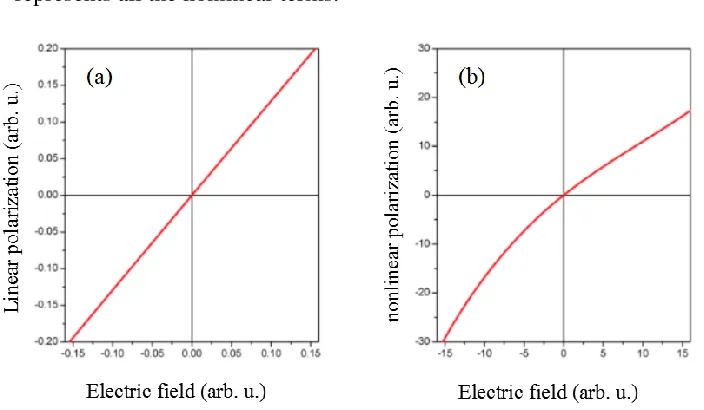
electric field is strong enough, the polarization P becomes nonlinear and can be expressed as:
where (1), (2) , , ( )n are the linear, second, third and n-th order susceptibility, PL = P(1) is linear polarization and PNL P(1)+P(2)+P(3)
represents all the nonlinear terms.
Figure 1.1 Typical (a) linear and (b) nonlinear polarization versus electric field curves.
We substitute +PNL for P and obtain:
where is a relative dielectric permittivity tensor. Since we consider dispersive media, the relative dielectric permittivity is a function of the frequency of the propagating light, . The time dependent electric field and the nonlinear polarization can be expressed as:
( , ) ( ) i nt . ., (1. 7)
n n
t
e c cE r E r
( , ) ( ) n . ., (1. 8)
NL N
n L n
i t t
e c c [image:30.593.105.457.235.440.2]5
If we insert the electric field and polarization from Eq. (1. 7) and Eq. (1. 8) into Eq. (1. 6), we obtain:
In typical situation the term
(
E r
n( ))
is much smaller than 2E rn( ). In particular, for a plane wave,
(
E r
n( )=0
)
. Neglecting this term in Eq.(1.9), we obtain:In real applications, we can choose the crystal orientation in such a way that the above vectorial equation can be simplifies to a scalar equation:
0
2
2 n
n n n
2 2
( )+k ( ) nNL( ), (1. 11)
c
E r E r P r
where we replaced by kn2. The Eq.(1.11) constitutes the time independent nonlinear wave equation.
1.3
Phase matching condition
Efficient nonlinear interaction depends sensitively on the relative phases between interacting beams. Different optical frequencies propagate with different phase velocities in a nonlinear medium because the refractive index is wavelength dependent. Collinear second harmonic generation in a uniform and isotropic nonlinear medium is the most prototypical and simplest nonlinear optical process. In this section, the phase matching condition in collinear second harmonic generation will be deduced from time independent nonlinear wave equation.
A fundamental plane wave with complex amplitude E1 propagating in z
direction of a nonlinear medium, will generate the second harmonic wave E2.
6 1
2
1 1
2 2
A ( ) , (1. 12) A ( ) , (1. 13)
ik z ik z z e z e E E
where k12n1/1 and k22n2/2 are the wave vectors of the fundamental beam (FB) and second harmonic (SH), n1, λ1, and n2, λ2 are
refractive indices and wavelengths of FB and SH, respectively. By applying Eq. (1. 12) and Eq. (1. 13) in Eq. (1. 11), we obtain:
1 1 0 2 2 2 1 1 1 2 2 (z)
+ ( ) NL( ), (1. 14)
d
k z z
dz c E E P 2 2 0 2 2 2 2 2 2 2 2 (z)
+ ( ) NL( ), (1. 15)
d
k z z
dz c
E
E P
According to Kleinman [13], the nonlinear polarization terms in the right hand side of Eq.(1.14) and (1.15) can be expressed as:
0 ij 2
*
1 ( ) 4 (z) 1(z), (1. 16) NL
z d
P E E
ii 0
2
2 ( ) 2 1( )z , (1. 17) NL z d
P E
The nonlinear coefficient dij represents elements of the quadratic
susceptibility tensor χ(2) by considering the so called Kleinman symmetry conditions. The nonlinear coefficient dij is a 3×6 matrix whose non-zero
components depend on the point group of the nonlinear medium. The following two examples depict nonlinear coefficient dij for lithium niobate
(LiNbO3, 3m point group) and calcium barium niobate (CBN, 4mm point
group).
3
31 22
22 22 31
31 31 33
0 0 0 0
0 0 0 , (1. 18)
0 0 0
LiNbO
d d
d d d d
d d d
15 CBN 15
31 31 33
0 0 0 0 0
0 0 0 0 0 , (1. 19)
0 0 0
d
d d
d d d
7
If we insert the electric fields and nonlinear polarizations from Eqs. (1. 12) and (1. 13) into Eqs. (1. 14) and (1. 15), and use the so called slowly varying envelope approximation (SVEA), which means
2
n n
2 2 n ,
d d
ik dz dz
A A
we obtain
dA1(z)
dz =
-2idij
w
1 2
c2k 1
A2(z)A 1
*
(z)e-i kz, (1. 20)
dA2(z)
dz = -idij
w
2 2
c2k 2
A12
(z)ei kz, (1. 21)
where k is the so-called phase mismatch parameter, which represents the dispersion induced difference in phase velocities of the FB and SH, and
2 2 1
k k k
.
We can further simplify Eq. (1. 21) by using the so called undepleted pump approximation, which assumes that the amplitude of the FB does not change with propagation distance when the conversion efficiency is very low. In this case, A1(z) is constant, and the above coupled wave equations reduce to one equation
dA2(z)
dz = -idij
w
2 2
c2k 2
A12ei kz
, (1. 22)
The solution to Eq. (1. 22) is
A2(z)=
-iA12d
ij
w
2 2
c2k 2
zsinc Dkz 2 æ èç ö ø÷e i kz
2 , (1. 23)
where the sinc function sinc( ) = sin( )/x x x. Therefore, the intensity of emitted second harmonic I2 2n2 0c A22 can be expressed as
2 2 2
1 1 2 2 2 3 2 0 1 2 (1. 24) 2 2
( ) d Iij z sinc .
I z
c n n
kz
8
Equation (1. 24) is a well-known equation which describes the intensity variation of SH when conversion efficiency is very small. Although it is obtained for plane waves in a specific case of collinear interaction using SVEA and undepleted pump approximation, it reflects some important characteristics for SHG. First of all, the intensity of SH is proportional to the square of the intensity of the fundamental beam. Second, the SH intensity depends strongly on the phase mismatch parameterk.
Phase mismatch between the interacting waves propagating in nonlinear materials is a major problem in early research of nonlinear optics [12, 15]. The essential reason for phase mismatch is that normally all nonlinear materials are dispersive. In the simplest case of SHG, the FB propagates with wave vector
k
1
2
n
1/
1 while the SH propagates with wave vector2
2
2/
2k
n
. We can see from Eq. (1. 24) that the strongest SHG could be achieved when k is zero, which means exact phase matching. In this case, we obtain Eq. (1. 25) and we can see that the intensity of SH increases quadratically with propagation distance.2 2 2 2 1 1 2 3 2 0 1 2 , 2
( ) I ijz (1. 25)
I z d c n n
In order to obtain exact phase matching, both energy conservation and momentum conservation are required, which can be expressed as
1 1
=
2(1 2
. 6)
,
1 1 1 1
=
2 2(1. 27)
n
n
n
,
We can deduce from the above two equations that this requires n1 = n2.
However, because almost all the materials are dispersive, the refractive indices are frequency-dependent. It is difficult to fulfill
n
1( ) = (
1n
2
2)
in real materials what results in nonzero phase mismatch
2 2 1 1
12 1 ( ) ( )
= 2 = 4 / (1. 28)
k k k n n
9 Equation (1. 25) can be written as
2 2 2
2( ) 1z sin( / 2) ,
/ 2
kz I z R
kz
I
where
0
2 2 1 3 2
1 2 2
.
ij
d R
c n n
From the mathematical point of view, this is a periodic
function with a period of Lc = π/k, as shown in Figure 1. 2. The parameter
Lc, defining the length of the nonlinear medium providing the maximum SHG
efficiency, is referred to as the coherence length and will be discussed in more details in section 1.3. From the physical point of view, the relative phase between FB and SH determines the direction of the energy flow between the interacting waves. Therefore, non-zero phase mismatch results in periodic alternation of the direction of energy flow between both waves. Initially the energy flows from fundamental to second harmonic and then back, after the relative phase between both waves reaches π.
Figure 1.2 Periodic oscillation of phase mismatched SHG along the propagation direction.
10
Figure 1.3 Dependence of phase mismatched SHG as a function of propagation distance in a thick quartz platelet [16].
Figure 1. 4 shows a typical curve for SH intensity as a function of k. We can see that a small deviation of k would lead to a dramatic decrease of SH intensity. In real applications, the phase mismatch in most nonlinear crystals is an order of 1 μm-1 making efficient SHG almost impossible to achieve.
Figure 1.4 Dependence of phase mismatched SH intensity as a function of propagation distance in a thick quartz platelet.
11
[18]. However, the most practically significant solutions are birefringent phase matching (BPM) [19, 20] and quasi phase matching (QPM) in nonlinear photonics crystals (NPCs) [12]. In the following section, we will mainly introduce BPM and QPM. The first one eliminates the phase mismatch by adjusting the phase velocities of the interacting waves. The second one provides a net compensation for the phase mismatch by modulating nonlinearity of the material. The advantages and disadvantages of these two techniques are discussed and compared.
1. 4 Methods of phase matching
1.4.1 Birefringent phase matching
Giordmaine and Maker, et al. independently reported that the phase mismatch of FB and SH in potassium dihydrogen phosphate (KDP) could be balanced out by carefully choosing the polarization of waves and propagation direction [8, 16]. This phase matching resulted in a 300-fold increase of SH intensity. Midwinter, et al. extended this technique, now known as birefringent phase matching (BPM), or index phase matching, to a more general case of three-wave mixing [14].
The crystal they used in the experiment, KDP, is a typical birefringent crystal. The refractive index of a birefringent crystal depends on the polarization and propagation direction of light. Usually crystal with non-cubic crystal structure is birefringent and one or two its special directions govern the optical anisotropy whereas all directions perpendicular to it (or at a given angle to it) are optically equivalent. Therefore, rotating the material around this axis does not change its optical behavior. This special direction is known as the optic axis of the crystal. Depending on the number of optic axes in a birefringent crystal, the latter is either a uniaxial or a biaxial. Light whose polarization is perpendicular to the optic axis is governed by the ordinary refractive index no, while that whose polarization is in the direction of the
12
Here we take LiNbO3 as an example to illustrate the theory of BPM.
LiNbO3 is a negative uniaxial crystal which means that ne is smaller than no at
the same wavelength (ne < no). Most of the nonlinear media have normal
dispersion, which means the refractive index of FB is smaller than the refractive index of SH, n(ω) < n(2ω). In order to fulfill the phase matching condition, the SH should be chosen as extraordinary wave, while for the FB we have two possibilities. In the first case, known as type-I phase matching, both FB photons have the same polarization (ordinary light). In the second case, known as type-II phase matching, two FB photons are mutually orthogonally polarized, i.e. one is ordinary and the second one extraordinary.
Figure 1.5 (a) Birefringent phase matching diagram in LiNbO3. (b) Refractive index
curves for the ordinarily and extraordinarily polarized beam in LiNbO3 [17].
Figure 1. 5 (a) shows the phase matching diagram for LiNbO3. The
refractive indices of ordinary and extraordinary light are indicated by a circle and an ellipse. We can see that at a certain propagation angle θ1, the refractive
index of an ordinary FB equals to the refractive index of an extraordinary SH. We obtain the type-I phase matching condition.
1 1
( )
(2 ) (1.29)
o e
n
n
,
At this propagation direction in the crystal, the differently polarized FB and SH components have the same phase velocities so that the phase matching condition is satisfied. Figure 1. 5 (b) shows the refractive index curves for LiNbO3. We can see that if the FB is ordinarily polarized at a
13
they will experience the same refractive index and consequently the phase matching condition will be fulfilled.
In the case of type-II phase matching, in order to eliminate the phase mismatch, the following equation should be fulfilled
2e 1o 1e
, (1.30)
k
k
k
where
k
1o ,k
1e andk
2e represent the wave vector of the ordinary FB, extraordinary FB and extraordinary SH. We can deduce from Eq. (1. 30) that2e
=(
1o+
1e) / 2, (1.31)
n
n
n
where n1o, n1e and n2e represent the refractive indices of the ordinary FB,
extraordinary FB and extraordinary SH, respectively. The propagation angle of type-II phase matching is indicated as θ2 in Figure 1. 5 (a). The
polarizations of interacting beams and the orientation of the crystal are rigorously chosen to fulfill the matching condition. This phase-matching technique is called angle tuning. Because it is very sensitive dependent on the angle of propagation, angle tuning is also known as critical phase matching.
Since refractive indices depend on temperature, one can obtain exact phase matching in a small range of FB wavelengths by tuning the temperature of the crystal [20]. Simultaneous control of both temperature and propagation direction makes it possible to fulfill exact phase matching condition in a continuous wavelength ranges of incident beams, ensuring very high conversion efficiency. Therefore, BPM technique is widely used in generating tunable coherent light sources, like optical parametric oscillators (OPO) and optical parametric amplifiers (OPA).
14
parallel propagation vectors quickly diverge from one another as they propagate through the crystal. This so-called walk-off effect limits the effective interaction length of the two waves and decreases the efficiency of any nonlinear mixing process involving such waves [21]. Although this problem could be solved by temperature tuning, the other two connatural disadvantages of BPM make it necessary to develop alternative phase matching techniques. First of all, due to the restrictive angular, temperature and wavelength acceptances, it is impossible to fulfill phase matching condition in arbitrary crystals and for arbitrary wavelengths. Some materials (like gallium arsenide, GaAs) may possess no birefringence, or may have insufficient birefringence to compensate for the dispersion over the desired wavelength range. For example, in LiNbO3 blue and ultra-violet (UV)
spectral range are inaccessible for BPM. Because of the vicinity of absorption edge, the dispersion curves change rapidly, and even by angle and temperature tuning, the phase matching condition could not be satisfied. The second disadvantage is that the BPM technique is limited to off-diagonal nonlinear tensor elements. In many crystals, like LiNbO3, lithium tantalate
(LiTaO3) and potassium titanyl phosphate (KTiOPO4 or KTP), the
off-diagonal components of nonlinear tensor are modest, typically below 5 pm/V (see table 1.1), resulting in low conversion efficiency.
Table 1.1 Nonzero nonlinear tensor components of LiNbO3, LiTaO3 and KTP [22].
LiNbO3 (pm/V) LiTaO3 (pm/V) KTP (pm/V)
d22 = 2.7
d31 = 4.5
d33 ≈ 27-34
d22 = 2.0
d31 = 1.0
d33 = 21
d15 = 2.7
d24 = 2.7
d31 = 2.7
d32 = 4.35
15
1.4.2 Quasi-phase matching
Quasi-phase matching (QPM) was a technique first proposed by Armstrong and Bloembergen in 1962 in their pioneering paper “Interactions between Light Waves in a Nonlinear Dielectric” [12]. As we discussed above, the SH intensity in a phase mismatched condition is a periodic function with a period of coherence length Lc=π/Δk. The curve A in Figure 1. 6 shows the SH
16
Figure 1.6 Intensity of SHG as a function of propagation distance in phase mismatched (curve A), QPM (curve B) and the exact phase matched (curve C) condition [12].
Periodic modulation of the nonlinear susceptibility can be realized not only by changing the sign of nonlinearity, but also by changing the value of the nonlinear coefficient. Chapter 2 will give more detailed introduction to different ways to fabricate QPM structures.
The SH intensity generated by a one dimensional QPM structure is mathematically described in the following part of this section. This will help us to better understand the mechanism of QPM and its advantages over BPM technique. The nonlinearity of a one-dimensional QPM structure with a period of can be expressed as Fourier series
2
( ) l , (1. 32)
il z iG z
l l
l l
d z D e D e
where
D
l is the Fourier coefficient of the l-th spatial frequency component and Gl = lk0 = 2lπ/ is the l-th multiple of the fundamental spatial frequency.Replacing dij in Eq. (1. 21) with d(z) and assuming undepleted pump approximation A1(z) = A1, we obtain
2 2 2 1 2 2 ( )
2( ) i Gl k z, (1. 33) l l d i A c k A z D e dz
17 2 2 1 2 ( 2 2 2 2 )
sinc ( )
( ) , (
2 1. 34)
m m
G k z i m
G k z iA
zD c k
A z e
and the intensity of SH
0
2 2 2
1 1 2 2
2
2 3 2
1
2
sinc ( )
( ) , (1. 35)
2
m Gm k
D I z z I n z c n
By contrast, equation 1.2. describes the SH intensity in a phase mismatched condition in homogenous crystal as
We can see that the original phase mismatch parameter Δk is replaced by the term (Gm – Δk), and nonlinearity dij by Fourier coefficient Dm. The quasi
phase match condition for efficient SHG is
QPM m=0, (1. 36) k k G
where
kQPM is the quasi phase match parameter and vectorG
m=2
m
/
is reciprocal lattice vector (RLV) of the QPM structure. RLV is provided by the periodicity of the structure to ensure momentum conservation2 +
k G
1 m=
k
2. Therefore, quasi phase matching condition can be written asQPM 2 2 1 m=0, (1. 37) k k k G
And the SH intensity becomes
QPM 2 2 2
1 1 2 2 3 2 0 1 2 2 2 s
( ) in , (1
2 . 38)
m k z
D I z c c n I z n
The nonlinearity of the QPM structure, denoted by d(z), can be expressed as a square wave function
eff
( ) sign cos(2 ) , (1. 39)
d z d z
18
period of the QPM structure. The spatial variation of d(z) can be described in terms of a Fourier series
eff
( ) m , (1. 40)
m
iG z m m d z d F e
Fm is the Fourier coefficient given by
2
sin( ), (1.41)
m
F m D m
where D = ld/Ʌ is the duty cycle of the QPM structure, ld is the length of the
inverted domain and Ʌ the period of reversal. For the QPM interaction, the period of the structure can be given by
2 1
, (1. 4 )/ 2
2 m k 2k
The SH intensity strongly depends on the modulation of nonlinearity d(z) via the Fourier coefficients Dm. In the case of a duty cycle of D = 50%, the
strongest Fourier coefficient Dm = dij·2/(mπ) is achieved. Therefore, we
obtain the SH intensity in a quasi-phase matched process
Note that the tendency for I2(z) to decrease with increasing values of m, it is
most desirable to achieve quasi-phase-matching with a first-order (m = 1) interaction. In this case, comparing the above formula with the SH intensity in BPM condition in Eq. (1. 25), we can see that the SH intensity in QPM condition is reduced by a factor of 4/(π2). However, as we discussed in last part of section 1.3.1, the BPM technique is limited to off diagonal elements of the nonlinear tensor dij while QPM technique can utilize the strongest element.
As a numerical example, the maximal component for congruent LiNbO3
(CLN) in BPM is d31 = 4.5 pm/V, and the strongest nonlinear coefficient is
d33 = 34.4 pm/V. If the first order QPM condition is fulfilled, then the
effective nonlinearity will be deff = d33·2/ π ≈ 21.9 pm/V, which means more
19
comparing with BPM. The advantages of QPM also include the flexibility and versatility of this technique. In principle, it allows for efficient nonlinear interactions in at any frequencies in the transparency range of the material, including materials without birefringence and wavelength range that BPM is inaccessible. In addition, the beam walk-off effect can be avoided in a QPM process by forcing all interacting waves to propagate at 90° angle with respect to the optical axis of the crystal. Furthermore, the period of a QPM structure can be adjusted in order to obtain a desired phase-matching temperature. Operation at or near room temperature is therefore often possible without resorting to critical phase matching or noncollinear phase matching. This option is important for nonlinear interactions in waveguides, where noncollinear beams usually cannot be used.
1.5 Noncollinear second harmonic generation
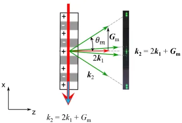
In the above sections, we introduced collinear SHG in nonlinear media and obtained the phase matching conditions. Second harmonic generation with harmonics emitted at nonzero angles with respect to the FB, i.e. noncollinear SHGs, have also been demonstrated both theoretically and experimentally. Considering the simplest case when FB propagates perpendicularly to the periodic modulation of the nonlinear susceptibility, as shown in Figure 1. 7, second harmonic waves can be emitted in different directions. As the emission of harmonics resembles the standard diffraction from the periodic index modulation, this process is called nonlinear diffraction [25].
In order to generate efficient noncollinear SHs, the following vectorial quasi phase matching condition needs to be fulfilled
2
2
1 m, (1. 44)20
Figure 1. 7 Collinear and noncollinear SHGs in a one dimensional nonlinear medium. The red arrows and green arrows indicate the wave vectors of the FB and SHGs. The green dots on the black background represent the far field of noncollinearly emitted second harmonic beams recorded by a CCD camera.
The quasi phase matching condition of nonlinear diffraction can be decomposed into the longitudinal component k2cosc 2k1 , and the transverse component k2sinm Gm.
It has been shown in Eq. (1. 38) that the efficient SH will be generated by satisfying only longitudinal phase matching condition. If this happens, the generated SH beam is called Cerenkov SH (CSH) [26-28]. This beam propagates at an angle defined as
1 c
2 2
arccos k , (1. 45)
k
On the other hand, when only the transverse phase matching condition is satisfied, a number of the SH beams is emitted at angles determined as
m
2
arcsin Gm , (1. 46)
k
[image:46.593.91.462.69.320.2]21
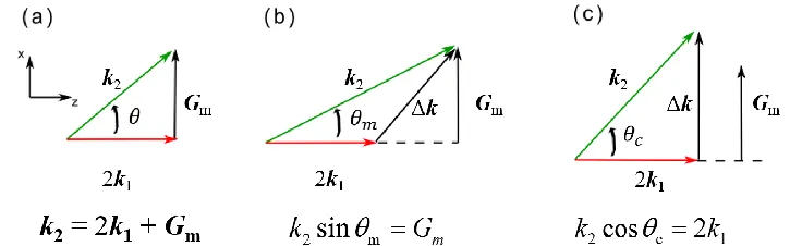
This SH emission is called the nonlinear Raman-Nath SH [29], in analogy with standard Raman-Nath diffraction in linear optics. Finally, when both transverse and longitudinal phase matching conditions are simultaneously satisfied the SH generation process is called nonlinear Bragg diffraction [30], again in analogy with the well known Bragg diffraction process in linear optics. The phase matching diagrams for nonlinear Bragg, Cerenkov and nonlinear Raman-Nath diffractions are shown in Figure 1. 8.
Figure 1. 8 Phase matching diagrams for (a) nonlinear Bragg diffraction, (b) nonlinear Raman-Nath diffraction and (c) nonlinear Cerenkov diffraction.
The CSHG was first theoretically predicted by Kleinman in 1962 and has been intensively investigated since its first experimental observation in 1968 [26-28]. It is of great interest in applications like all-optical signal processing, owing to its unique properties including high conversion efficiency and noncollinear emission. One can manipulate the emission properties of the CSHG by either changing the angle of the FB, or by introducing reciprocal lattice vectors along the propagation direction of the FB [31-33]. It has also been demonstrated that the intensity of the CSHG is sensitive to the wavelength, diameter and position of the incident FB [34-36]. Cerenkov harmonic irradiations have also been experimentally observed in other parametric processes, including difference frequency generation (DFG) and high order cascading processes [37, 38].
[image:47.593.135.503.224.337.2]22
cascaded Raman-Nath THG, have been readily observed and studied in nonlinear media with spatially modulated χ(2) [39, 40].
1.6 Motivation and thesis arrangement
Quasi-phase matching allows for efficient nonlinear interactions by spatially modulating second order susceptibility, χ(2), which brings appropriate reciprocal lattice vectors in phase matching diagrams and makes it a flexible and versatile method for applications like optical frequency conversion, beam shaping, quantum entanglement manipulation, etc. The development of QPM technique relies on advances in χ(2) engineering approaches and inventions of
novel χ(2) structures in versatile material systems. This thesis explores further improvement of QPM technique in these three aspects. Specifically, four key topics were investigated, including an advanced technique for fabricating QPM structures, a new material for broadband optical frequency conversion, a custom cut periodically poled lithium niobate (PPLN) for cascading frequency conversion processes and nonlinear diffraction in orientation-patterned semiconductors. This thesis is organized as follows.
Chapter 2 provides an overview of QPM techniques, various QPM structures, as well as details on fabrication and visualization of χ(2) spatially modulated structures. This chapter also reviews the milestones in literatures which have contributed to the developments of QPM.
Chapter 3 presents a detailed study on femtosecond laser poling technique and its application to QPM. Laser poling is a direct writing technique which can be easily employed for fabrication of various domain structures without the requirement for any high voltage facility, photolithography masks or ultra-clean environment. The parameters for optical poling using an infrared femtosecond laser were systematically investigated. As a demonstration of this all optical poling technique, a QPM structure was inscribed on a LiNbO3 channel waveguide for frequency
doubling of a 815 nm light.
23
conversion. The commonly used SBN crystal suffers from a low Curie temperature, which limits its applications at high pump powers. Ca0.28Ba0.72Nb2O6 (CBN-28) crystal possesses a much higher phase transition
temperature and therefore could be used as a broadband frequency converter even in elevated temperature. The spatial distribution and polarization properties of the emitted radiation were analyzed.
Chapter 5 presents a study on multistep cascading frequency conversion processes in a custom-cut PPLN. The traditional collinear QPM interaction and noncollinear Cerenkov frequency generations were combined in one single PPLN crystal. This approach offers the advantages of both interaction mechanisms to achieve higher conversion efficiency of high order harmonic generation via cascading processes. As a demonstration, enhanced fourth harmonic generation (FHG) was experimentally realized.
Chapter 6 presents a study on nonlinear diffraction in orientation patterned semiconductors. QPM in semiconductors offers a variety of nonlinear interactions, in particular, in infrared. However, in most cases only the collinear interaction along direction of the second order nonlinearity modulation has been considered. This chapter demonstrates noncollinear quadratic interactions in orientation patterned GaAs (OP-GaAs). It is also shows that the Cerenkov SHG can be used as an effective nondestructive technique for 3D visualization and diagnosis of domain structures inside semiconductors.
24
Chapter 2 Fundamental aspects
of nonlinear optics in quadratic
media
2.1 Introduction
25
Figure 2. 1 A stack of thin plates of nonlinear medium periodically rotated by 180° to realize QPM [12].
Over the past 40 years, improvements in photolithography method and breakthrough in external electric filed poling (EFP) make QPM a mature industrial technique. Parallel to the advances in technology are the emergences of abundant new materials and structural schemes, all of which have promoted the application of QPM in more areas. This chapter provides an overview of the milestones in literatures which have contributed to the developments of QPM. Specifically, four aspects of QPM technique are discussed, including commonly used QPM materials, advanced design of QPM structures, development of poling techniques for ferroelectrics crystals and QPM structures visualization methods.
2.2 QPM materials
With increasing demands for QPM technique operating at higher efficiencies over a broader range of powers as well as extended wavelength ranges, increasing attention has been paid to other parameters of QPM materials besides nonlinear susceptibility. These parameters include low absorption and scattering losses, high surface-damage threshold, high thermal conductivity, low thermo-optic coefficients, ease of crystal growth and processing, and environmental stability. This subsection gives a brief literature review on two kinds of commonly used QPM materials, including ferroelectric crystals and orientation patterned semiconductors.
2.2.1 Domain engineering in ferroelectrics
Lithium niobate (LiNbO3 or LN) is a negative uniaxial ferroelectric crystal