ON TESTING LASER ABLATION PROCESSES FOR ASTEROID DEFLECTION
2011 IAA Planetary Defense Conference
09-12 May 2011
Bucharest, Romania
Miss Alison Gibbings (1), Dr John-Mark Hopkins,(2), Dr David Burns(2) Dr Massimiliano Vasile (1)
(1)
University of Strathclyde,
75 Montrose Street, Glasgow, UK
[email protected]; [email protected]
(2)
Institute of Photonics, University of Strathclyde,
Wolfson Centre, 106 Rottenrow, Glasgow, UK [email protected]; [email protected]
ABSTRACT
Laser surface ablation has been theoretically demonstrated to be an advantageous method in the potential mitigation and deflection of Near Earth Asteroids. However to fully verify this approach a series of experiments were performed that examined the development of the ejecta plume induced by each ablation event. This included the flow rate, velocity and dispersion as a function of the target material’s composition. The rate of degradation onto optical surfaces was also assessed. The results demonstrated the sensitivity of the ablation process to the specific laser characteristics and properties of the chosen target material. This is relative to the focal point of the laser, the volumetric removal of the ejected material, the material phase changes within the ablation volume and the dispersion of the ejecta plume.
INTRODUCTION
Asteroids represent both an opportunity and a risk. Their pristine environment captures the early formation of the solar system; while their impact potential could result in the mass extinction of life. Potential methods of asteroid mitigation and deflection have therefore been addressed by numerous authors [1] [2] [3]. Amongst the many possibilities to deflect Near Earth Asteroids, laser ablation has been shown to be theoretically one of the most effective cases [4]. No catastrophic fragmentation of the asteroid occurs. Neither does the technique suffer from any heavy mass penalties or the additional complexity of physical attachment and landing devices.
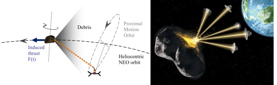
Laser ablation is achieved by irradiating the surface of an asteroid by a laser light source. The laser can either be powered by a nuclear reactor or highly efficient solar arrays [24] [25]. For direct solar pumping ultra-light, deployable reflectors can be used to concentrate the incoming solar light into the laser medium. The resulting laser light is targeted onto the asteroid. This is achieved by focusing optics and enables the surface rock to sublimate, transforming directly from a solid to a gas. Material subsequently expands into a debris cloud of gas, dust and ejecta. This action provides a continuously low thrust that, over an extended period of time, can deflect asteroid(s) away from a potentially threatening trajectory [5] [4] [6] [7] [1]. This action is therefore considered to be a thrust analogue of standard methods of rocket propulsion.
Even with a relatively low warning time, medium to small size asteroids (typical 50-500 m in diameters) can be deflected by thousands of kilometres [6][8]. During the deflection event both the asteroid and the spacecraft are in close proximity to each other (100-300 m away). For example, with a single spacecraft utilizing a laser output power of 6.5 kW a surface power density of 1.5 MW/m2 can be achieved. This is enough to induce the ablation deflection event. A spot size of 8-9 cm in diameter would result in a plume density ranging from 1*10-5 – 1*10-15 kg/m3. The exact value depends on the distance from the spot and view angle. This is respect to the center line of the plume. Both variables decrease with an increasing distance away from the asteroid.
period simulations have shown that using 2-3 spacecraft with a similar output power would result in a miss distance of 1000-1500 km. If the output laser power was increased to 26 kW, with a spot size diameter of 20 cm, three spacecraft would obtain a miss distance of 5000-7000 km. The potential for deflection is therefore dependent on the number of spacecraft located within the vicinity of the asteroid and their combined laser power. Contamination of the optics was also considered. The concept, called Laser Bees was therefore considered to be scaleable to the given mission scenario and target asteroid. This is further illustrated in Fig 1:
Fig 1: A Schematic of the Asteroid Ablation Mitigation Technique (left); a Multiple Laser-bee Concept: (right)
However, to have complete confidence in the laser ablation approach further experimental investigation is required. Assumptions must be verified and fundamental questions answered. Current models assume that the asteroid’s body is a spherical, dense, non porous, homogenous structure. Forsterite (Mg2SiO4) is typically used to represent asteroids.
However asteroids exist over an extended range of material compositions, geometries and surface features. Models must therefore be advanced to represent the diversity within the asteroid population.
The nature, composition and geometry of the ejecta plume also require accurate modeling. Current analogues compare the plume profile to be similar to that of a rocket exhaust. Based upon cometary modeling, larger reservoirs of subsurface icy material are therefore assumed to be located on the surface of each asteroid [9][10]. These reservoirs expand, and are subsequently accelerated into the vacuum of space. This is considered suitable for loose rubble-pile asteroids. However it was deemed to be inadequate for other families of asteroids. This includes rocky, brittle bodies and highly porous structures. The ejecta plume profile(s) is highly dependent on the structural dynamics and material characteristics of the selected body [8].
The expansion of the ejecta plume for both highly porous and inhomogeneous structures remains unknown. For a highly porous asteroid the gas could expand inside the target material. This would significantly reduce the formation of the ejecta plume. Or alternatively the internal expansion and compaction could occur instantaneously. This would create a very thin later of material where surface ablation could occur. If the latter is true then laser ablation could also be highly effective on porous asteroids. Therefore, substantial verification is required. The relative flow-rate, velocity and dispersion of the ablated material will ultimately define the modulus and direction of the imparted force exerted onto the asteroid. The evolution of the ejecta will also have a significant affect on the contamination and operations (i.e. endurance) of any optical surface. These issues are fundamental to the asteroid ablation technique. Therefore to successfully assess the effectiveness and efficiency of the laser ablation technique a detailed understanding of these parameters is required.
To examine the feasibility of laser ablation as an appropriate means for asteroidal deflection a series of self contained scaled experiments using a 90 W continuous-wave (CW) laser was performed. For each ablation experiment the overriding influence on the target material composition – dense, porous and inhomogeneous – was assessed. A variety of cases were studied. This aimed to represent the diversity of possible asteroid deflection events. Each event was assessed as a function of the ejecta plume – mass flow, velocity and dispersion geometry – and the rate of optical contamination. The collected data has then been compared against the theoretical prediction. This enabled calibration of the current analytical modeling technique [4][5]. Ultimately the experiment provided a detailed insight into the effectiveness of the laser system, mission scenarios, system preparations and, most importantly, the laser ablation potential as a viable method of deflecting Near Earth Asteroids.
Induced thrust F(t)
Debris
Heliocentric NEO orbit
Within this paper, the current modeling technique for surface ablation is initially given. The experimental arrangement is then described. This includes the nature of the asteroid analogue target material and component selection. The results are presented where comparison against the theoretical prediction has been performed. Current conclusions and areas of future work are then addressed.
MODELLING OF ABLATION
The theoretical mass flow rate and velocity of the ejecta plume, and the total imparted acceleration of the asteroid (by the ejecta plume) for each ablation event can be modeled from the energy balance of sublimation [4][5][6][11]. This combines the absorption of the laser beam, PIN, the heat losses of conduction, QCOND, and radiation, QRAD respectively,
and the sublimation enthalpy of the asteroid Ev. Ev wasassumed to be 19.686*10 6
J/kg. This is based on the material properties of silicon [12].
Therefore during sublimation the mass flow of the ablated material can be expressed as:
(
IN RAD COND)
vQ
Q
P
E
dt
dm
−
−
=
1
(1)If the mass flow is negative then there is not enough available energy to initiate the surface ablation process.
The heat loss due to radiation was assumed to act as a black-body and is therefore defined as [5]:
(
4 4)
O SUB SPOT SB
RAD
A
T
T
Q
=
σ
ε
−
(2)Similarity the heat loss due to conduction can be determined by [5][11]:
(
)
t
c
A
T
T
Q
A ASPOT SUB
COND
π
κ
ρ
4 0
4
−
=
(3)σSB is the Stefan-Boltzmann constant (5.6704*10 -8
W/m2K4), ε is the black body emissivity of the asteroid, ASPOT is the
area of the laser’s spot size, TSUB is the sublimation temperature of the asteroid (in vacuum conditions) and To is the
temperature at the centre of the asteroid. cA, ρA and k are the heat capacity, density and thermal conductivity of the
asteroid respectively. t is the sublimation duration. During the simulations the physical properties of the asteroid were assumed to be similar to that of silicon and silica. This was to replicate the conduction of silica based, s-type, asteroids. It also coincided with the experiment’s asteroid analogue target material; a silica dominated material. The assumed physical properties are given in Table 1:
Table 1: Assumed Asteroid Parameters
Parameter Value
Sublimation enthalpy, Ev[12]. 19.686*106 J/kg
Black body emissivity of unglazed silica, ε [22] 0.80 Sublimation temperature, TSUB [19] 1700 K
Temperature at the centre of the asteroid, To 278 K
Heat capacity [23] 703 J/kgK
Thermal conductivity [23] 1.38 W/mK
The average velocity of the ejecta plume can be calculated from Maxwell’s distribution of an ideal gas [11][5]
. This is defined by the sublimation temperature, TSUB, the molar mass, Ma, and Boltzman’s constant, k. This is given by:
8
suba
kT
v
M
π
The force acting on the asteroid is therefore given as a product of the ejecta velocity and the mass flow of the ablated material. A scattering factor (2/ π) is used to account for the dispersion of the ejecta plume. Over the given half sphere it is assumed that all the ejected material expands uniformly. However, this assumption requires quantitative assessment. A constrained cone of ejecta might be more plausible. Nevertheless the force, FSUB, and magnitude of the induced
acceleration, a, is given by:
exp
2
•=
v
m
F
SUBπ
(5)i SUB
m
F
a
=
∴
(6)The density of the ejecta plume can also be expressed analytically [5][10]. At a given distance, r, from the spot location, and at an angle, θ, measured from the surface normal, the density of the ejecta can be expressed as:
(
)
1 2 2 2 22
cos
2
*
)
,
(
−
+
=
k MAX SPOT SPOT Pd
r
d
A
r
θ
πθ
ρ
θ
ρ
(7)This follows a normal distribution pattern. It also assumes a continuous mono-energetic vapor-only flow regime. No ionization occurs. Therefore the flow is assumed to be a friction-free, compressible gas. This is typically classified with a constant adiabatic index, where for diatomic molecules, k = 1.4. The same approach is used to model cometary sublimation and is further classified as an analogue of the standard rocket equation [9] [10]. Therefore the density at the nozzle is given as:
v
A
m
k
P
SPOT k SPOT exp 1 1*
;
2
1
1
*
• − −=
−
+
=
ρ
ρ
(8)The jet constant, Ap, for diatomic molecules is defined as 0.345 with the limited expansion angle, θMAX as 130.45
degrees. PSPOT is the pressure at the spot location. This is commonly known as the ablation pressure and can be
determined from the laws of conservation [20]. This follows:
t
A
v
m
P
SPOT SPOT −=
(9)Within the local vicinity of the ejecta flow, any optical surface will be subjected to increased rates of contamination and degradation. It is currently assumed that all particles of ejecta that come into contact with a surface will re-condense and stick. The variation of ejecta thickness on any optical surface can therefore be expressed as [5][10]:
)
cos(
2
vf layerv
dt
dh
ψ
ρ
ρ
=
(10)ψvf is the view angle. This is equal to the angle between the ejected flow and the normal of the optical surface. To
account for the expansion of gas in a vacuum the average velocity is multiplied by a factor of two. ρlayer is the layer
density. This is assumed to be 1 g/cm2. The increased rates of contamination will ultimately reduce the laser beam’s power density on the surface of the asteroid. The degradation factor, τ, is based on the Lambert-Beer-Bougier law and can be defined as [5][10]:
end h
e
ητ
=
2(11)
The momentum coupling coefficient, Cm, can also be determined [13] [14] [15]. At the surface of the asteroid this is defined
by the ratio of ablation momentum to the incident laser energy. The intensity of the laser beam, I (W/m2), is therefore characterized at the surface.
I
P
C
SPOTm
=
(12)The ratio of laser energy to ablated mass, denoted Q*, can also be calculated. The efficiency, ηab, at which the laser
energy is converted into ejecta kinetic energy, is also given by [13] [14]:
E m m
E
AB
C
Q
C
V
E
MV
=
=
∆
=
2 *2
2
η
(13)EXPERIMENTAL DESIGN
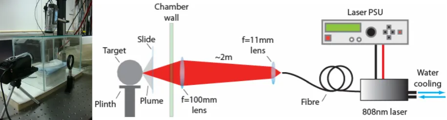
A 90 W CW fibre-coupled semiconductor laser (LIMO 90-F200-DL808), was used as the laser source for all experiments. The laser was mounted horizontally and cooled via a fast flow rate recirculating chiller at 15 °C. The output from the 2m long, 200µm-core fibre umbilical was collimated with an f=11mm aspheric lens. This allowed for the laser light to propagate across an optical table to approximately fill (~75%) a 50.8mm diameter f=100mm lens. Both lenses were antireflection coated for the laser wavelength at 808 nm. The second lens focused the laser to an approximate spot size radius of 0.25 mm at the target material. An approximate surface power density, accounting for losses, of 37 kW/cm2 was achieved at the focus. All experiments occurred within a sealed and self contained glass test chamber. Under standard atmospheric conditions, the environment within the test chamber was purged with nitrogen gas. This was to reduce the occurrence of atmospheric combustion to negligible levels. Any innate material combustion still occurred. The utmost care and attention was taken to ensure that the experiment was designed to be an appropriately scaled analogue of the asteroid deflection event(s). All measurements – ejected mass, optical contamination etc - were assessed as a function of time. To provide statistical viable and well calibrated data-points each experiment was repeated five times.
[image:5.595.70.528.583.706.2]Within the test chamber each asteroid analogue target material was mounted on a raised pedestal. This was located at a pre-determined location, relative to the focal point of the laser beam. Before each experiment the laser was run just above the threshold, at a power level of ~ 2 W. The residual visible spot (the eye is still slightly sensitive at 808 nm) was used to align the laser focus onto the surface of the target material. In-situ monitoring systems surrounded the test chamber. This included two CMOS high resolution, high speed digital cameras (Panasonic HDC-SD60), and a third dedicated FLIR thermal camera (SC7000). The transparent test chamber enabled the cameras to monitor all event(s) and to provide a point-of-entry for the laser. The two CMOS cameras provided 1920*1080 resolution recording at two thousand images per second. A high shutter control was used to ensure detailed recording of the ablation event(s). Each CMOS camera was mounted orthogonally to each other. This enabled for the formation of the ejecta plume to be assessed. The thermal camera was used to measure the temperature of the spot and the ejecta plume. The positioning and selection of the cameras provided a large field of view. This covered the entire ablation volume. The experiment’s configuration is shown in Fig 2.
To measure the potential rates and local distribution of any optical contamination and degradation highly cleaned and polished microscopic slides where located within the local vicinity of the flow field. This is again shown in Fig 2. Based on current simulations each slide was positioned, following a spherical pattern, 5 cm away, downstream of the target material. During each ablation experiment the ejected material – gas, dust and particles – were collected onto the microscopic slides. This enables the reflectivity of the contaminated surfaces to be assessed. This is considered to be a function of temperature, time and angle (relative to the surface normal). Significant amounts of optical degradation will greatly diminish the power available for the laser ablation technique. This would affect the systems’ ability of generating thrust. The evaporation and re-condensation of the ejected gas needs to be considered. Current models assume that all the ejected particles impacting the surface of the slides will immediately condense and stick. The validity of this assumption will be thoroughly investigated. Mass measurements of the microscopic slides before and after each ablation event was also recorded and assessed. This enabled the surface density as a function of distance from the spot location, angle and time to be considered and compared to the numerical model.
Additional mass measurements of the pre-and-post ablated target material were also conducted. This enabled the rate of sublimation to be determined. A thermocouple was also positioned onto the target material. This enabled the heat transfer during each ablation event to be evaluated. Three different categories of target material were considered. This included a dense, highly porous and inhomogeneous profile. For preliminary tests each target material was volumetrically similar; shaped into a 3 cm diameter sphere. This ensured the same degree of surface curvature and therefore allowed quantitative comparison of the ablated response to occur. In future test campaigns a more realistic and representative shape model of an asteroid will be tested. This will include an elliptically irregular potato shape.
Quartz sandstone was used to replicate a dense, solid asteroid. This was considered to be representative of silica, s-type asteroids. A composite mixture of expanded perlite, fly ash and quartz sand was used to model a highly porous, rubble-pile asteroid [16][17]. This is relative to the porosity, albedo and composition. The highly porous, composite mixture was achieved by mixing, by mass 17 % dry quartz sand, 15 % expanded perlite, 25 % fly ash and 43 % water [16]. During the manufacturing processing the dry particles were mixed first, and then the water was added. This was to avoid clumping of the particles, and ensured an even blend within the mixture. Care was taken not to unduly compress the individual grains of expanded perlite. Once mixed the mixture was placed in a 3 cm diameter mould and allowed to cure for five days. Curing enabled the particles to settle allowing for a chemical reaction to occur between all the particles. Fly ash was used as the main cementing agent. This ensured that the grains of expanded perlite and quartz sand would not separate. Quartz sand was used to fill the void space between the grains of expanded perlite; thereby providing the required bulk porosity and density. Expanded perlite provided the main source of porosity within the target material. It is characterized as a highly porous, easily crushable, silicate aggregate. Once cured the composite samples were then placed in an oven and baked-out at 90 C for two days [16]. During bake-out the samples were periodically removed and their mass measured. This ensured volumetric removal of the water. After bake-out each sample is cooled. A long cooling time is used to minimize the creation of any internal thermal stress within the target material.
Two inhomogeneous samples (a highly porous and a dense, consolidated structure) of target material were also tested. The results of these samples are not reported within this publication. The dense inhomogeneous sample was sourced from impure sandstone. Large particles of sandy aggregates and clay were present. The highly porous inhomogeneous material was manufactured by varying the length-scale relationship between the laser beam and the largest grains of the expanded perlite. Variation only occurred in the expanded perlite as it was the largest particle. Also based on previous experiments the length-scale affect for sand particles has a negligible affect [18]. Therefore to introduce significant inhomogeneity into the target material the selection of particles had to be much larger than the incoming laser spot size (0.25 mm radius). A nominal grain size of 1-6 mm was therefore selected.
RESULTS
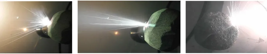
Two different samples – the dense sandstone and the highly porous composite mixture – were thoroughly tested. Each ejecta plume contained smoke, gas and ejected particles. However a clear distinction in the ablation response and ejecta profile was identified. This included a temporal variation in cone angle and the rate of the ablated material. For the dense, quartz sandstone sample the cone angle and rate of ablation decreased with time. Given in Fig 3 an initial cone angle of 94.83 degrees was observed. This decreased to 23.27 degrees, where a far more focused plume was created. In contrast the highly porous sample experienced a far wider and relatively constant cone angle (approximately 159 degrees). Data has been analyzed through image processing. The variation in cone angle has not yet been considered in the numerical models. A constant scattering factor was used to account for the dispersion of the ejecta plume.
During ablation, both samples also experienced the volumetric removal of material. This was is contraction to the expected shallow-surface layer ablation. 10-4 g/s of material was removed. While this corresponded well to the numerical prediction (an error of less than ten percent), it created a narrow tunneling effect of approximately 5 mm in length for the solid sandstone sample and 20 mm in length for the highly porous composite sample. Volumetrically, the more material that is removed the greater the deviation away from the initial surface focus point. Therefore in the solid sandstone sample the tunneling effect creates a subsurface grove, similar to that of a rocket exhaust. This would have assisted in the focusing of the ejecta plume. The highly porous sample is less affected by this influence; more pore space is available for the ejecta to escape, and at wider angles. Therefore the cone angle remains large. Eventually the laser intensity decreases below the required sublimation point and ablation stops. This corresponds to a decrease and a halt in the ejected mass flow.
Increasing the ablation hole depth also serves to increase the rate of heat loss by conduction. Increased penetration depth leads to the volumetric heating of the target material. The transport of the ablated material becomes far less effective. Attenuation of the laser beam also becomes an important parameter. This includes the absorptive affect of the ejecta particles and gaseous contributions of the plume. Within the ablation volume the increase of temperature changed the optical properties of the material. A semi-melted glassy material was located within the ablation volume, whereas a re-condensed white residue was located around the ablation rim. These depositions do not contribute to the formation of the ejecta plume. These factors will ultimately result in the laser decreasing its available irradiance and potential for asteroid deflection. Critically these issues are time dependent.
CONCLUDING REMARKS & FUTURE WORK
[image:7.595.82.517.204.293.2]It can be concluded that laser ablation is highly dependent on the material properties of the chosen target. Results showed that ablation is highly sensitive to the focal point of the laser. This is dominated by the volumetric removal of the target material. This affects the rate at which the ablated material is removed, the induced cone angle and characteristics of the ejecta. The ablation process was also influenced by changes to the surface material. However work is still required to fully investigate and confirm the ablation process. For future experimental campaigns all ablation events will occur within a vacuum chamber. This will enable a near-space environment to be created. A pump-down pressure of < 10-6 mbar will ensure maximum spread of the plume and will also remove the particle drag disturbance of an atmosphere [21]. Despite the nitrogen purge environment providing a non-reactive atmosphere it may have still influenced the ejection and distribution of the ejecta plume and possible attenuation of the laser beam. Collision with the nitrogen elements would have damped the motion of particles; free expansion was not possible. Off-axis incidence of the laser beam with the surface of the target will also be assessed. The in-homogenous samples will also be tested. To provide a more realistic and representative shape-model of asteroids an elliptical and irregular potato-shape will be used. The samples will also be mounted on the end of a pendulum (or low friction mounting). For each ablation event this will enable the associated transitional and rotational change of momentum to be measured and the resultant force
calculated. A pulsed laser will also be used to test the response to higher energy ablation. The nature of the ejecta plume will also be examined in greater detail. This will be achieved by optical microscopy and/or a Scanning Electron Microscope of the contaminated microscopic slides.
ACKNOWLEDGMENTS
This work has been sponsored by the Planetary Society, USA and was conducted within the Institute of Photonics, University of Strathclyde and the Space Advanced Research Team at the University of Strathclyde and the University of Glasgow.
REFERENCES
[1] Melosh, H.J., Nemchinov, I.V., Zetzer, Y.I “Non-nuclear Strategies for Deflecting Comets and Asteroids”, in: Gehrels, T (Ed.), Hazards due to Comets and Asteroids. University of Arizona Press, Tucson, pp. 1111–1132, 1994 [2] Conway, B.A “Near-optimal Deflection of Earth-approaching Asteroids”. J. Guidance, Control and Dynamics 24 (5), 1035–1037, 2001
[3] Gritzner, C., Kahle, R Mitigation Technologies and their Requirements, in: Belton, M., Morgan, T., Samarainha, N., Yeomans, D. (Eds.), Mitigation of Hazardous Comets and Asteroid. Cambridge University Press, Cambridge, pp. 167– 200, 2004
[4] Sanchez, J.P., Colombo, C., Vasile, M., et al “Multicriteria comparison among several mitigation strategies for dangerous Near-Earth objects”. J. Guid. Control Dynam. 32, 121–141, 2009.
[5] Vasile M, Maddock C “On the Deflection of Asteroids with Mirrors”, Celestial Mechanical Dynamics, Vol 107, pg 265-284, 2010
[6] Vasile M., Maddock C., Radice G., McInnes C NEO Deflection though a Multi-Mirror System, ESA Call for Proposals: Encounter 2029, Final Report for Ariadna Study Contract 08/4301, Technical officer: Summerer L, 2009. [7] Campbell, Jonathan W et al “The Impact Imperative: Laser Ablation for Deflecting Asteroids, Meteoroids, and Comets from Impacting the Earth” First International Symposium on Beamed Energy, 2009
[8] Vasile M “Mirror Bees – A Concept for Asteroid Deflection and Hazard Mitigation”. University of Glasgow, Research Proposal , 2009
[9] Komle NI “Jet and Shell Structures in the Cometary Coma: Modelling and Observations. Comet Halley: Investigation, Results, Interpretations”. Editor JW Mason pg 231-244, Vol 1, 1990
[10] Kahle R, Kuhrt E, Hahn G, Knolenberg J “Physical Limits of Solar Collectors in Deflecting Earth-threatening Asteroids” Advanced Science and Technology, Vol 10, pg 256-263, 2006
[11] Sanchez, JP “Asteroid Hazard Mitigation: Deflection Models and Mission Analysis” PhD Thesis, University og Glasgow, 2009
[12] Integrated Materials “Physical Properies of Silicon” [Online] Available at
<http://www.integratedmaterials.com/en/technology/science_of_silicon/physical_properties_of_silicon> 2011 [13] Phipps C, Birkan M, Bohn W et al “Review: Laser Ablation Propulsion”, Journal of Propulsion and Power, Vol 26, No 4, 2010
[14] Phipps C, Luke J “Diode Laser-Drive Microthrusters: A New Departure for Micropropulsion”, AIAA, Vol 40, No 2, 2002
[15] Sinko JEM Phipps C, “Modelling Co2 Laser Ablation Impulse of Polymers in Vapour and Plasma Regime”, Applied Physics Letter 95, 121105, 2009
[16] Housen “Collisional Fragmentation of Rotating Bodies”, Lunar and Planetary Science XXXV, No 1826, 2004 [17] Housen K.R, Holsapple K “Impact Cratering On Porous Asteroids”. Academic Press, Icarus 163. Pg 102-119, 2002 [18] Housen, In Correspondence, 2010
[19] Ranc, G “Continuous Vacuum Sublimation of Silica”, Laboratory of Physics, Minces, 1969
[20] Zheng Z, Zhang Y, Zhouu W et al “High Coupling Efficiency Generation in Water Confined Laser Plasma Propulsion”, China Physical Letter, Vol 25, No 2, pg 501, 2007
[21] Dettleff G “Plume Flow and Plume Impingement in Space Technology”, Aerospace Science, Vol 28, pg 1-71, 1991 [22] Omega “Table of Emissivity Values” [Online] Available at <
http://www.ib.cnea.gov.ar/~experim2/Cosas/omega/emisivity.htm> 2010
[23] Del Mar Ventures “Fused Silica” [Online] Available at <http://www.sciner.com/Opticsland/FS.htm> 2010
[24] Maddock, C.A “On the dynamics, navigation and control of a spacecraft formation of solar concentrators in the proximity of an asteroid” PhD thesis, University of Glasgow.