EFFECT OF COLD ARC TO DEFLECTION IN
CONTINUOUS WELDING OF THIN PLATE
LEE SHI GUO
B051210238
UNIVERSITI TEKNIKAL MALAYSIA MELAKA
EFFECT OF COLD ARC TO DEFLECTION IN CONTINUOUS
WELDING OF THIN PLATE
This report submitted in accordance with requirement of the Universiti Teknikal
Malaysia Melaka (UTeM) for the Bachelor Degree of Manufacturing Engineering (Manufacturing Process) (Hons)
By
LEE SHI GUO B051210238 920327016787
UNIVERSITI TEKNIKAL MALAYSIA MELAKA
BORANG PENGESAHAN STATUS LAPORAN PROJEK SARJANA MUDA
TAJUK: Effect of Cold Arc to Deflection in Continuous Welding of Thin Plate
SESI PENGAJIAN: 2015/16 Semester 2
Saya LEE SHI GUO
mengaku membenarkan Laporan PSM ini disimpan di Perpustakaan Universiti Teknikal Malaysia Melaka (UTeM) dengan syarat-syarat kegunaan seperti berikut: 1. Laporan PSM adalah hak milik Universiti Teknikal Malaysia Melaka dan penulis. 2. Perpustakaan Universiti Teknikal Malaysia Melaka dibenarkan membuat salinan
untuk tujuan pengajian sahaja dengan izin penulis.
3. Perpustakaan dibenarkan membuat salinan laporan PSM ini sebagai bahan pertukaran antara institusi pengajian tinggi.
4. **Sila tandakan ( )
SULIT (Mengandungi maklumat yang berdarjah keselamatan atau kepentingan Malaysia sebagaimana yang termaktub dalam AKTA RAHSIA RASMI 1972)
(Mengandungi maklumat TERHAD yang telah ditentukan oleh organisasi/badan di mana penyelidikan dijalankan)
Alamat Tetap: NO. 12 Jalan Kota 8, Taman Kota Yong Peng 83700 Yong Peng, Johor
Tarikh: ________________________
Disahkan oleh:
Cop Rasmi:
Tarikh: _______________________
** Jika Laporan PSM ini SULIT atau TERHAD, sila lampirkan surat daripada pihak berkuasa/organisasi berkenaan dengan menyatakan sekali sebab dan tempoh laporan PSM ini perlu dikelaskan sebagai SULIT atau TERHAD.
TERHAD
DECLARATION
I hereby, declared this report entitled “Effect of Cold Arc to Deflection in Continuous
Welding of Thin Plate” is the results of my own research except as cited in references.
Signature : ……….
Author’s Name : Lee Shi Guo
APPROVAL
This report is submitted to the Faculty of Manufacturing Engineering of UTeM as a partial fulfillment of the requirements for the degree of Bachelor of Manufacturing Engineering (Manufacturing Process) (Hons.). The members of the supervisory committee are as follow:
………
(Principal Supervisor)
………
(Co-Supervisor)
i
ABSTRAK
Industri kapal dan automotif menggunakan plat nipis untuk pembinaan kapal dan badan kereta secara meluas. Masalah herotan meningkat dengan penggunaan plat nipis dalam industri kapal dan automotif. Proses kimpalan dengan input haba yang rendah boleh mengurangkan herotan, sebagai contoh, proses kimpalan ‘Cold arc’. Oleh itu, proses kimpalan ‘Cold arc’ digunakan dalam eksperimen ini. Objektif untuk kajian ini adalah untuk mengkaji kesan parameter proses kimpalan ‘Cold arc’ kepada herotan, mencadangkan parameter terbaik
untuk proses kimpalan ‘Cold arc’ menurut sifat-sifat kekuatan tegangan, dan membandingkan herotan yang berlaku dalam eksperimen kepada keputusan simulasi. Yang pertama, nilai parameter dipilih adalah arus elektrik, voltan dan kelajuan kimpalan. Selepas proses kampilan, herotan diukur dengan pembaris dan ujian kekuatan tegangan dijalankan untuk mengetahui sifat kekuatan tegangan. Selepas itu, keputusan diperolehi daripada eksperimen dikumpulkan dan dibincangkan. Kemudian, ABAQUS digunakan untuk mensimulasikan herotan dan keputusan simulasi ini dibandingkan dengan keputusan eksperimen. Hasil kajian menunjukkan proses kimpalan ‘Cold arc’ mengurangkan masalah herotan dengan berkesan
ii
ABSTRACT
iii
DEDICATION
To my beloved parents
Lee Tow Huat
iv
ADKNOWLEDGEMENT
I would like to express my sincere appreciation to my project supervisor, PM Dr. Nur Izan Syahriah binti Hussein for the support given throughout the duration for this research. Besides, the constructive comments and guidance given by her is very helpful to overcome all the difficulties in this research.
v
TABLE OF CONTENT
Abstrak i
Abstract ii
Dedication iii
Acknowledgement iv
Table of Content v
List of Tables viii
List of Figures ix
List of Abbreviations, Symbols and Nomenclature xi
CHAPTER 1: INTRODUCTION 1
1.1 Background Study 1
1.2 Problem Statement 2
1.3 Objectives 2
1.4 Scope of Study 3
1.5 Significance of Study 3
1.6 Project Planning 4
CHAPTER 2: LITERATURE REVIEW 5
2.1 Introduction 5
2.2 Arc Welding 5
2.2.1 Arc Welding Power Sources 6
2.2.2 Types of Arc Welding 6
2.3 Gas metal arc welding (GMAW) 8
2.3.1 Process Characteristics 8
2.3.2 Transfer modes of GMAW 9
2.3.3 Advantages of GMAW 10
2.3.4 Limitations of GMAW 10
vi 2.4 Low Distortion Welding Process for Thin Plate 11
2.4.1 Cold Metal Transfer (CMT) 11
2.4.2 Tandem Gas Metal Arc Welding 12
2.4.3 Cold Arc Welding 14
2.5 Cold Arc Welding 15
2.5.1 Comparison between GMAW and Cold Arc Welding Process 15 2.5.2 Arc Output of the Cold Arc Process on Re-ignition 17
2.6 Material and Application 17
2.6.1 Base Material 18
2.6.2 Wire Electrode 20
2.7 Welding Parameters 21
2.7.1 Current, Voltage and Welding Speed 21 2.7.2 Effect of Welding Parameters on Mechanical Properties of Materials 21
2.8 Distortion 24
2.8.1 Residual Stress 24
2.8.2 Types of Welding Distortion 25
2.8.3 Welding Distortion and Residual Stress Prediction 26 2.8.3 Techniques in Welding Distortion Measurement 27
CHAPTER 3: METHODOLOGY 29
3.1 Flowchart 30
3.2 Material Selection 32
3.2.1 Materials 32
3.2.2 Base Material 32
3.2.3 Wire Electrode 33
3.3 Material Preparation 33
3.4 Welding parameters selection 34
3.5 Equipment Set-up 35
3.6 Distortion Simulation by Using ABAQUS 37
vii
3.8 Tensile Testing 39
3.8.1 Tensile Specimens Preparation 39
3.8.2 Tensile Testing 40
CHAPTER 4: RESULTS AND DISCUSSION 41
4.1 Weldment Condition 42
4.1.1 Results 42
4.1.2 Discussion 45
4.1.2.1 Shielding gas 46
4.1.2 .2 Heat input 46
4.2 Distortion Measurement 47
4.2.1 Results 47
4.2.2 Discussion 50
4.3 Tensile Testing 51
4.3.1 Results 51
4.3.2 Discussion 52
4.4 Distortion Simulation by Using ABAQUS 55
4.4.1 Results 55
4.4.2 Discussion 56
CHAPTER 5: CONCLUSION AND RECOMMENDATIONS 57
REFERENCES 60
APPENDICES 65
Appendix A: Gantt Chart for PSM 1 Appendix B: Gantt Chart for PSM 2
Appendix C: Typical GMAW Parameters of Groove Welds in Aluminium Appendix D: Table of Strength Before and After Welding
viii
LIST OF TABLES
Table 2.1: Chemical composition of aluminium alloy 19 Table 2.2: Chemical composition of research steels 19 Table 2.3: Mechanical properties of AA 5052, DP800, HSLA340 and DC04 19 Table 2.4: Optimized value of welding parameters 21 Table 2.5: Tensile values for IS2062 and IS45C8 joint 22 Table 2.6: Micro hardness values at different weld regions 22
Table 3.1: Chemical composition of AA 5052 in weight % 32
Table 3.2: Tensile properties of AA 5052 32
Table 3.3: Chemical composition of ER5356 in wt % 33
Table 3.4: Welding parameters 34
Table 3.5: Typical GMAW parameters of groove welds in aluminium 34 Table 3.6: Procedure for creating the distorted part 38
Table 4.1: Difference set of parameters 42
Table 4.2: Welding results 42
Table 4.3: Distortion measurement results 49
Table 4.4: Tensile properties of each specimen 52
ix
LIST OF FIGURES
Figure 2.1: Basic arc welding circuit 6
Figure 2.2: The operation of SAW 7
Figure 2.3: The operation of GTAW 7
Figure2.4: The operation of GMAW 8
Figure 2.5: Principle of CMT process 11
Figure 2.6: Arc voltage and current in the CMT process 12
Figure 2.7: The operation of T-GMAW 13
Figure 2.8: Principle of T-GMAW process 13
Figure 2.9: Mixed aluminium / steel joints with zinc-based wires 14 Figure 2.10: Material (schematic), current and voltage outlines in short arc welding 15 Figure 2.11: Material transfer (schematic), current and voltage outlines in cold arc welding 16 Figure 2.12: Sequence of the material transfer in cold arc welding process 16 Figure 2.13: Comparison of arc output between cold arc and short arc welding 17 Figure 2.14: Example of application of aluminum body panel 18 Figure 2.15 : Mechanical properties of sample 1 and 2 20 Figure 2.16: Fatigue life versus welding current diagram for 50 cm/min welding speed 23 Figure 2.17: Penetration versus welding current diagram for 50 cm/min welding speed 23 Figure 2.18: Residual stresses in butt welding 24
Figure 2.19: Types of welding distortion 25
Figure 2.20: Residual stress distribution 26
Figure 2.21: Deflection distribution 26
x Figure 3.1(a): Flow chart conducting the experiment, part I 30 Figure 3.1 (b): Flow chart conducting the experiment, part II 31
Figure 3.2: 2 mm AA5052 aluminium alloy plates 33
Figure 3. 4: Jig for clamping thin plates 35
Figure 3.3: Welding equipment set-up 35
Figure 3.5: Schematic diagram for showing the welding gap in between two plates 36
Figure 3.6: Alpha Q RC2 36
Figure 3.7: Flow chart of residual stress prediction 37 Figure 3.8: Measuring angular distortion by a ruler (Feng, 2005b) 39 Figure 3.9: Dimensions of tensile specimen according to ASTM E8M-04 (mm) 39
Figure 3.10: Universal Testing Machine (UTM) 40
Figure 4.1: Lack of penetration 45
Figure 4.2: Measuring distortion by a ruler 47
Figure 4.3: Experiment 1 47
Figure 4.4: Experiment 2 48
Figure 4.5: Experiment 3 48
Figure 4.6: Experiment 4 48
Figure 4.7: Experiment 5 49
Figure 4.8: Experiment 6 49
Figure 4.9: Clamping jig 50
Figure 4.10: Tensile specimens 51
Figure 4.11: Fractured tensile specimens 51
xi
LIST OF ABBREVIATIONS, SYMBOLS AND
NOMENCLATURE
GMAW - Gas Metal Arc Welding
GTAW - Gas Tungsten Arc Welding
SAW - Submerged Arc Welding
CMT - Cold Metal Transfer
T-GMAW - Tandem Gas Metal Arc Welding HSLA - High Strength Low Alloy
DP - Dual-phase
HAZ - Heat Affected Zone
LVDT - Linear Variable Differential Transformer η - Efficiency factor for welding process
1
CHAPTER 1
INTRODUCTION
1.1 Background Study
In recent years, ship and automotive manufacturers tend to use thin plates for constructing ship and automotive body. Thin plates are popular among the manufacturers because it will minimize transports’ weight and reduce the fabrication work. When the weight of the ship or car body reduced, the fuel cost will be reducing simultaneously. Besides, the increased use of higher strength steel and aluminium alloys becomes one of the reasons that the manufacturers choose thinner plates in ship and car structure (Shen, 2013) (Sakurai, 2008). However, the increased of thin plate will cause the increased of distortion. This is because thinner material is more susceptible, as it has less stiffness (Beardsley, 2009).
2 1.2 Problem Statement
Nowadays, an increased use of aluminium and steel thin plates with the thickness of less than 10 mm in panel fabrications has resulted in significant increased of distortion (Mandal, 2004a). When more manufacturers use thin plate for building naval ship and automotive body, the amount of distortion will increase because thinner material is more susceptible, as it has less stiffness (Beardsley, 2009). The minimum thickness of thin plates is 3 mm for naval ship and 0.3 mm for automotive body (Mandal, 2004a). Welding will produce residual stress and this stress may cause distortion. Uneven temperature distribution caused by the intense heat source is the main reason that distortion will occurred (Mandal, 2004a).
When distortion happened, rework will be carried out. This causes wasting a lot of money. A good example that showing the rework cost spent on the distortion parts which is the thin-plate distortion rectification work on the Arleigh Burke Destroyer class in US Navy. It cost 2.5 million Europe Dollar for the whole rework process (Gray, 2014). EWM deliver an innovative welding process, cold arc welding process, which can reduce the distortion problem to the least. Therefore, it is important to understand the effect of adjusting the parameters of cold arc welding process to the distortion.
1.3 Objectives
Objectives of this study are:
i. To study the effect of cold arc welding parameters to distortion of welded thin plate
ii. To suggest the optimum set of parameters for cold arc welding process according to tensile properties
3 1.4 Scope of Study
Scopes of this study are:
Raw material is thin aluminium alloy sheet that is AA 5250.
Thin sheet thickness is 2 mm.
Cold arc welding process was used throughout the entire project.
Parameters which have been studied were current (80-100 A), voltage (16-19 V),
and welding travel speed (0.65-1.0 m/min).
Thermo-elastic-plastic finite element method based on ABAQUS code was used
to simulate distortion.
1.5 Significance of Study
The study of the effect of continuously cold arc welding process on thin plate is important because many manufacturers use aluminium alloys and steel thin plate to construct their products by welding process. This study can give significant benefit for ship and vehicle construction industry. Shipbuilding industry wasting a lot of money in the rectification work on distortion, for example, shipbuilding industry cost seven figures on a medium-range destroyer for rectification works (McPherson, 2007). Therefore, cold arc welding process can reduce distortion problems on steel thin plate; simultaneously this welding process can reduce the rectification costs.
4 1.6 Project Planning
5
CHAPTER 2
LITERATURE REVIEW
2.1 Introduction
Firstly, basic of welding was reviewed. Welding can be classified into few categories such as arc welding, oxyfuel gas welding, resistance welding, solid-state welding and others. After that, variant of GMAW, cold arc welding process was described. Next, type of material and the thickness of the thin plate are importance elements of this study; therefore, these two importance elements were explored. Moreover, the parameters of cold arc welding process were focused because these parameters will minimize the welding distortion. Finally, distortion was reviewed because distortion is one of the welding defects that will often occur on the thin plate. From the above reviewing, literature review was divided into few importance sub-topics. For example, arc welding, cold arc welding, material and application, welding parameters and distortion.
2.2 Arc Welding
6 2.2.1 Arc Welding Power Sources
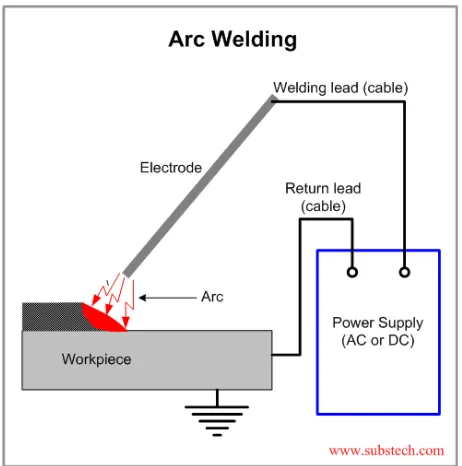
Figure 2.1: Basic arc welding circuit (Kopeliovich, 2012)
Figure 2.1 shows the basic arc welding circuit, AC or DC power source is connected to the work piece and the electrode holder (Anonymous, 2015). Normally, arc welding is used with low-voltage and high current in between the electrode and work piece. Generally, voltage is reduced to a suitable voltage range 20 to 80 V by arc welding power source. With the same power source, current is adjusted to a suitable current range from 50 to 1500 A (Mandal, 2004b).
2.2.2 Types of Arc Welding
7 Submerged Arc Welding (SAW) is operated under a fact that was the welding arc in between the electrode and the base metal was ‘submerged’ under a layer of
granular fusible flux. Flux is fed from a flux hopper in a stable condition for keeping the arc and molten pool area submerged from the atmospheric oxygen and nitrogen. The flux provides a layer of slag on the surface of filler metal. SAW can be operated under either semi-automatic or automatic mode (Gibson, 1997a).
Figure 2.2: The operation of SAW (Admin, 2015)
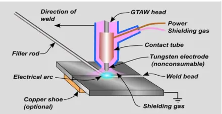
[image:24.612.237.457.552.665.2]Gas Tungsten Arc Welding (GTAW) also known as Tungsten Inert Gas Welding (TIG). An electric arc provides the heat source in between the non-consumable tungsten electrode and the base metal. A shielding gas protects the electrode and molten weld pool from atmosphere oxygen and nitrogen. Normally, argon and helium, or the mixture of argon and helium are used as the shielding gas. The most used mixture is 85% argon/ 15% hydrogen (Gibson, 1997b).