1 INTRODUCTION
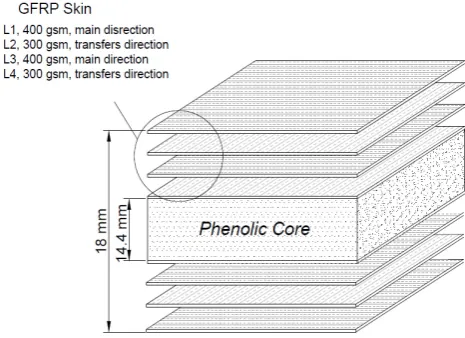
Engineers have been developing different types of FRP sandwich panel for structural applications in civil, mechanical and aeronautical engineering. FRP sandwich panels have an acceptable structural be-haviour due to their ability to carry a high flexural load and light weight. This type of construction could be used in different structural types such as FRP layered beam, floor panel and pedestrian bridge deck. LOC Composites Pty Ltd has fabricated a new structural FRP sandwich panel for applications; floors, pedestrian bridges and railways (Van-Erp and Rogers 2008). The sandwich panel is made from ECR-glass fibre skins and modified phenolic solid core as shown in Figure 1. Four plies glass fibre with 0/90o were used in the top and bottom skin of the panel. The innovative FRP sandwich panel is expected to be used in the civil engineering applica-tions instead of the traditional plywood panel. An experimental investigation of this type of sandwich structures was carried out by Manalo et al. (2010). The experimental work showed that this panel could be used in the structural applications as main loaded members.
Multi-objective design optimization has been ap-plied to optimize the new FRP composite structures recently. Omaker et al. (2009) presented a new model for multi objective design optimization of laminate FRP composite structures. The new model depends on the basis of Quantum Particle Swarm Optimization (QPSO) and it is applied for finding the weight and cost minimization. Murthy et al.
(2006) presented an optimization of strength and stiffness for the honeycomb sandwich panel. It was concluded that the maximum bending stiffness oc-curred at the core to skin weight ratio equal to 2.04. Walker and Smith (2003) presented multi-objective design optimization of fibre composite structure by using FE and genetic algorithms (GA). It was found that the weight and deflection as a multi-objective could be optimized by the GA to suite the design engineers requirements. Park et al. (2009) optimized the FRP composite one-way plate made from carbon fibre and fibre glass. A GA was used to find the op-timum design of plate in a single and multi-objective form. An orientation 0/90o was used for the plies pa-rametric study to find the effect of the plies number on the cost and weight objectives.
[image:1.595.308.541.607.776.2]
Figure 1. FRP Sandwich Panel Profile
Multi-objective design optimization of an innovative fibre composite
sandwich panel for civil engineering applications
Z. K. Awad, T. Aravinthan &Y. Zhuge
Centre of Excellence in Engineered Fibre Composites (CEEFC), USQ, Toowoomba, Australia
F. Gonzalez
Faculty of Built Environment & Engineering, QUT, Brisbane, Australia
However, the literature review revealed that there is a lack of optimization studies in the design of FRP domestic floor panel. The present study tries to find out the optimum design of two-way innovative FRP sandwich floor panel. The design variables are the plies orientation, plies thicknesses and core thick-ness. The objective of this study is to minimize the cost and the weight of the innovative panel. The multi- objective simulated Annealing (MOSA) method is used to find the optimum design variables.
2 FE SIMULATION OF SANDWICH PANEL The FE simulation is formulated for the analysis of FRP composite sandwich panel by using ABAQUS commercial software. The experimental testing indi-cated that the behaviour of the FRP skin is approxi-mately linear; the behaviour of core material is lin-ear in tension and non-linlin-ear in compression. The full details of the FE model and materials model are described in Awad et al. (2009). The material speci-fications are shown in Table 1. The top and bottom skins are formulated by using shell element type S8R (8- node doubly curved shell element). The core is meshed by using 3D solid element type C3D20R. The interaction between skin and core is assumed to be full and there is no slip between them. The Hashin elastic failure model was used to find the failure part through the FRP skin plies. The damage of FRP materials is considered and it depends on Hashin failure theory. Hashin theory considers four types of failure: fibre tension, fibre compression, matrix tension and matrix compression (Hashin 1980).
Table 1. Material properties Mate-rial Type Density Kg/m3 Elastic Modulu s MPa Pois-son Ra-tio Ultimate Tensile strain% Tensile strengt h MPa FRP
Skin 1800 23,550 0.3 0.018 376.8 Core 850 1,154 0.2 0.0061 5.95
The damage initiation criteria (F) in the four cases are:
Fibre in tension:
2 2
t 1 1 1 2
f T L
F n
X S
(1)
Fibre in compression:
2
C 1 1
f C
F
X
(2)
Matrix in tension:
2 2
t 22 12
m T L
F n
Y S
(3) Matrix in compression:
2
2 C 2
C 2 2 2 2 1 2
m C T C L
Y
F 1
Y 2 S Y S
(4) Where XT = tension and XC = compression strength in longitudinal direction, YT = tension and YC = compression strength in transverse direction. SL and ST are shear in longitudinal and transverse direc-tions. n = factor represents shear contribution in the tensile fibre initiation (0 or 1.0). 11and 22 = normal
stresses; 12 = shear stress. Core material is
consid-ered relatively similar to concrete behaviour. There-fore, the plasticity of the concrete model was used to simulate the nonlinear behaviour of the core.
3 DESIGN OPTIMIZATION
Multi objective optimization is very essential in the real design of aerospace and civil engineering struc-tures. The single objective simulated annealing was developed by Kirkpatrick et al. (1983). It is consid-ered as the basis of the multi-objective optimization (Paya et al. 2008).The single objective optimization gives an optimum set of design variables with re-spect to single objective, while the same variables give an unacceptable design for other objectives. A reasonable design solution could be reached by us-ing a combination of more than sus-ingle objective by using multi-objective design optimization (Konak et al. 2006). Pareto optimal set procedure is preferred in the multi objective design optimization. In the movement from one Pareto solution to another solu-tion, there is always an amount of loses in one ob-jective to achieve some gain in the other obob-jective. The multi-objective optimization method gives a set of solutions and the best solution measured regard-ing to all objective functions. Engineers are always like to get only one value from the set of solutions. Therefore, solving Multi-objective optimization problems can be conducted by both searching and decision making (Bui & Alam 2008). In the present research, MOSA is used to find the solution for the cost and weight minimization objectives of the FRL floor panel. The MOSA is a powerful method with high convergence rate in the solution of multi objec-tive design optimization (Alrefaei and Diabat 2009; Nam and Park 2002).
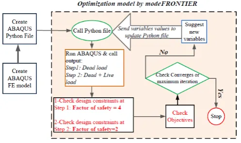
In this work, simulated Annealing (SA) was im-plemented in modeFRONTIER. There are two ex-ternal parameters to control the evolution system; the temperature (T) and the energy (E). When the initial configuration is introduced, the difference in the energy of the two states can be introduced:
final initial
E E E
(5)
E
P ( E ) exp
T
(6)
[image:3.595.37.280.213.607.2]There are several points regard as an optimum so-lution in the multi-objective optimization design and there is no unique solution. These points or solutions are called Pareto solutions; the set of solutions can be called either “trade-off surface” or Pareto fron-tier. After finding a set of solution the decision mak-ing is essential to reduce the number of solutions to a preferred solution. The optimization layout is shown in Figure 2. The two-way FRP sandwich panel case study has dimensions 600mm x 600 mm and four edges simply supported as shown in Figure 3. The existing FRP sandwich panel has unequal fi-bre thicknesses in x and y directions as shown previ-ously in Figure 1.
Figure 2. Optimization layout
Figure 3.Square FRP floor panel
3.1 Cost objective optimization
One of the disadvantages of fibre composite structures is a high initial fabrication cost. Develop-ing an optimum design method of FRP composite structure is very important to avoid materials waste. Moreover, any form of FRP structure must be opti-mized in order to minimize the material cost (Hol-laway & Head 1999). The cost of materials is re-quired in the design of the FRP sandwich panel because the FRP sandwich has two materials with different costs. Core material is regarded as low cost compared to the skin material cost. The core part can have different material properties and few types of configurations such as: voided, solid and corrugated
core. In the present research, the cost of FRP skin is assumed five times the cost of phenolic core. The rate of skin to core cost affects the optimum design objective function and this will affect directly the skin to core thickness ratio as the FRP sandwich floor area same for both skin and core. The loading on the panel is based on AS/NZS 1170.1:2002 speci-fications for the serviceability requirements and it is explained in Table 2. The cost objective is:
Cost obj. = [(Thick.*cost)skins +(Thick. *cost)core]
*Floor area (7) EUROCOMP constraints:
Tfu
Tf F.S
(8)
Cfu Cf
F.S
(9)
TCu TC
F.S
(10)
TCu CC
F.S
(11) Span / 250mm (12)
Where, σTf= allowable tensile, σCf= allowable compressive stress of FRP skin material;
TC=allowable tensile and σCC= allowable compres-sive stresses of the core material; Tfu = tension and
Cfu = compression strength of the FRP skin. TCu = tension and CCu = compression strength of the core materials; F.S = design factor of safety, which is as-sumed equal to four in the step one of the dead load and it represents the long-term load factor. A factor of safety equal to two is assumed for all total load cases (live and dead load) as explained in Table 2; δ = the total vertical deflection.
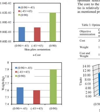
The optimization design starts with initial design of the existing FRP sandwich panel as shown in Fig-ure 1. The optimization results of the cost minimiza-tion is shown in Figure 4-a. The results show that the optimum skin plies orientation is ±45o with total cost 0.00989 units. This cost is less than the initial design cost of the FRP sandwich panel, which it is equal to 0.01164 units. The design details are shown in Table 3. The deflection of the initial design panel under service load is equal to 0.00278 m, which is greater than the allowable deflection (span/250).
Table 2. Design Parameters
Dead Load Dead Load + Point Live Load Load 4 kN/m2
4 kN/m2 + 1.8 kN
Factor of safety 4 2
Allowable
[image:3.595.34.283.278.425.2]Allowable
stress for core 5.25 MPa 10.5 MPa
3.2 Weight objective optimization
The weight benefit of a sandwich panel construc-tion is relatively light weight, due to the core con-figuration with low density and voided style. There are a few types of FRP sandwich panels such as solid core, voided core and honeycomb panel. The objective of developing this new FRP sandwich panel is to replace the traditional wood panel. The disadvantage of traditional wood panel is the degra-dation under the effects of weather and termite. Therefore, the new FRP panel should have better re-sistance to the degradation effects and slightly higher self-weight than wood. In the present re-search, weigh minimization was considered as an objective of the optimum design of FRP floor panel. The design constraints are same as mentioned above in equations (7-11). The weight objective is:
Weight obj. =[(Thick.*dens.)skins+(Thick. *dens.)core] *Floor area (13)
The optimization results for weight minimization are shown in Figure 4-b. The results show that the optimum skin plies orientation is ±45o with total weight equal to 7.6 kg.
a-Cost
b-Weight Figure 4. Cost and weight objectives
[image:4.595.41.385.417.803.2]3.3 Cost and weight multi-objective optimization The optimum design results for single objective are shown in Figure 4. The cost objective shows that the optimum configuration for the two-way FRP sand-wich panel skin is ±45o. Also, the weight objective shows the same result for the skin orientation. The final decision is a skin orientation at ±45o, is the op-timal with the results shown in Table 3. The opti-mum design challenge is to design the two objec-tives simultaneously in order to get an optimum design FRP sandwich panel for both cost and weight minimization. Three different plies orientations were studied and the results of the objectives are shown in Figure 5. It can be confirmed that the orientation ±45o is the optimum for multi-objective results. The objectives scatter chart for the solution of orientation ±45o is shown in Figure 6. There are two points in the scatter chart located in the optimal Pareto set, whereas one of them can be selected for further evaluation. The decision was made that the top point is selected as it has the minimum cost in the scatter chart. Design history for orientation ±45o of the two objectives is shown in Figure 7. The results of this optimum selected point are described in Table 3. The core to the skins thickness ratio is 8.28; this ra-tio is relatively higher than the initial design of 4.0 as mentioned previously in Figure 1.
Table 3. Optimum design results for orientation ±45o
Objective minimization
Core th. mm
45/-45o th.
mm
Cost unit
Weigh t kg
Defl . mm
Cost 20.15 0.367 0.0098 no 2.39
Weight 15.1 0.835 no 7.6 2.38
Cost and
[image:4.595.307.556.511.803.2]Figure 5. Multi-objectives analysis for the three orientations
[image:5.595.48.285.95.249.2]Figure 6. Scatter chart for cost and weight objectives
Figure 7. Design history for Multi-Objective Optimization
4 FE ANALYSIS AND FACTOR OF SAFETY ANALYSIS
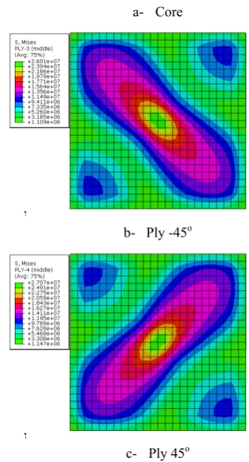
An FEA is important to determine the behaviour of the optimized two-way FRP sandwich panel with 600 mm span (four edges supports). The FE model was developed with the nonlinear core material be-haviour. The stress distribution in the service load level for both core and skins is shown in Figure 8. It was found that the behaviour of the FRP sandwich two-way panel is linear up to failure. The bottom skin fails before the top skin at load factor approxi-mately equal to 6. As the load increase, failure starts to occur on the top skin as shown in Figure 9.
a- Core
b- Ply -45o
c- Ply 45o
[image:5.595.45.285.296.442.2]Figure 8.Von-Mises stress at service load
Figure 9.Load factor – deflection
5 CONCLUDING REMARKS
The optimization of two-way FRP sandwich floor panel showed that one layer of ±45o FRP skin is
enough to design the FRP two-way sandwich panel. A multi-objective optimization analysis presented a Pareto set of optimal variables and the design point located between the single objective design of the cost and the weight. The optimization processes re-duce the cost and the weight of the existing FRP sandwich panel. The optimized panel showed an
ac-One of those points is optimum
[image:5.595.314.548.451.608.2]ceptable factor of safety and service deflection within the allowable limit. Further work will focus on multi-objective robust/uncertainty design and comparing the results with experimental analysis. 6 REFERENCES
Alrefaei, M.H. & Diabat, AH 2009. A simulated annealing technique for multi-objective simulation optimization. Ap-plied Mathematics and Computation 215(8): 3029-35. Awad, Z.K., Aravinthan, T. & Zhuge, Y. 2009. Finite Element
Analysis of Fibre Composite Sandwich Panel. Southern Engineering Conference, Springfeild, Qld, Australia. Bui, L. & Alam, S. 2008, Multi-Objective Optimization in
Computational Intelligence: Theory and Practice. Informa-tion Science Publishing.
Van-Erp, G. & Rogers, D. 2008. A Highly Sustainable Fibre Composite Building Panel. SustainableProcurement Con-ference, Brisbane, Australia.
Hashin, Z. 1980. Failure criteria for unidirectional fiber com-posites. Journal of Applied Mechanics 47(2): 329-34. Hollaway, L.C. & Head, P.R. 1999. Composite materials and
structures in civil engineering. In C.H. Zweben & A. Kelly (eds), Comperhensive Composite Materials. vol. 6. El-sevier: Oxford,
Kirkpatrick, S & Gelatt, C 1983. Optimization by simulated annealing. Science 220(4598): 671-80.
Konak, A., Coit, D.W. & Smith, A.E. 2006. Multi-objective optimization using genetic algorithms: A tutorial. Reliabil-ity Engineering & System Safety 91( 9): 992-1007.
Manalo, A.C., Aravinthan, T., Karunasena, W. & Islam, M.M. 2010. Flexural behaviour of structural fibre composite sandwich beams in flatwise and edgewise positions. Com-posite Structures ( 92): 984–95.
Murthy, O, Munirudrappa, N, Srikanth, L & Rao, R 2006, 'Strength and stiffness optimization studies on honeycomb core sandwich panels', Journal of Reinforced Plastics and Composites, vol. 25, no. 6, p. 663.
Nam, D. & Park, C. 2002. Pareto-based cost simulated anneal-ing for multiobjective optimization', Proceedings of the 4th Asia-Pacific Conference on Simulated Evolution and Learning (SEAL’02), Singapore.
Omkar, S., Khandelwal, R., Ananth, T., Narayana Naik, G. & Gopalakrishnan, S. 2009, 'Quantum behaved Particle Swarm Optimization (QPSO) for multi-objective design optimization of composite structures', Expert Systems With Applications 36(8): 11312-11322.
Park, C.H., Saouab, A., Bréard, J., Han, W.S., Vautrin, A. & Lee, W.I. 2009. An integrated optimisation for the weight, the structural performance and the cost of composite struc-tures. Composites Science and Technology 69(7-8):1101-7. Paya, I., Yepes, V., Gonzalez-Vidosa, F. & Hospitaler, A.
2008. Multiobjective optimization of concrete frames by simulated annealing. Computer-Aided Civil and Infrastruc-ture Engineering 23(8):596-610.
Rigoni, E 2003, MOSA–Multi-objective simulated annealing, Tech. Rep. 003, Esteco srl.
Walker, M. & Smith, R.E. 2003. A technique for the multiob-jective optimisation of laminated composite structures