Faculty of Mechanical and Manufacturing
Engineering Technology
DESIGN AND DEVELOP A DAMPER TO REDUCE VIBRATION
IN MILLING OPERATION
Dave Wong Wei Ye
Bachelor of Manufacturing engineering technology (Process and Technology) with Honours
UNIVERSITI TEKNIKAL MALAYSIA MELAKA
BORANG PENGESAHAN STATUS LAPORAN PROJEK SARJANA MUDA
TAJUK: DESIGN AND DEVELOP A DAMPER TO REDUCE VIBRATION IN MILLING OPERATION
SESI PENGAJIAN: 2017/18 Semester 2
Saya DAVE WONG WEI YE
mengaku membenarkan Laporan PSM ini disimpan di Perpustakaan Universiti Teknikal Malaysia Melaka (UTeM) dengan syarat-syarat kegunaan seperti berikut:
1. Laporan PSM adalah hak milik Universiti Teknikal Malaysia Melaka dan penulis. 2. Perpustakaan Universiti Teknikal Malaysia Melaka dibenarkan membuat salinan untuk
tujuan pengajian sahaja dengan izin penulis.
3. Perpustakaan dibenarkan membuat salinan laporan PSM ini sebagai bahan pertukaran antara institusi pengajian tinggi.
4. **Sila tandakan ( ) SULIT
TERHAD
TIDAK TERHAD
(Mengandungi maklumat yang berdarjah keselamatan atau kepentingan Malaysia sebagaimana yang termaktub dalam AKTA RAHSIA RASMI 1972)
(Mengandungi maklumat TERHAD yang telah ditentukan oleh organisasi/badan di mana penyelidikan dijalankan)
Alamat Tetap:
D41, JALAN PISANG EMAS, KANGKAR PULAI, 81110 JOHOR BAHRU, JOHOR.
Tarikh: ________________________
Disahkan oleh:
Cop Rasmi:
Tarikh: _______________________
i DECLARATION
I hereby, declared this report entitled “Design and Develop A Damper to Reduce Vibration in Milling Operation” is the results of my own research except as cited in references. The thesis has not been accepted for any degree and is not concurrently submitted in candidature of any other degree
Signature : ……….
Author’s Name : DAVE WONG WEI YE
ii APPROVAL
This report is submitted to the Faculty of Engineering Technology of UTeM as a partial fulfillment of the requirements for the degree of Bachelor of Manufacturing engineering technology (Process and Technology) with Honours. The member of the supervisory is as follow:
……….
iii ABSTRAK
iv ABSTRACT
v
DEDICATION
To my beloved parents, Wong Kien Chong and Puah Meng Choo. To my respected supervisor, Encik Mohammad Khalid bin Wahid.
vi ACKNOWLEDGEMENTS
I would like to thank Universiti Teknikal Malaysia Melaka (UTeM) for providing a precious
vii
TABLE OF CONTENT
DECLARATION i
APPROVAL ii
ABSTRAK iii
ABSTRACT iv
DEDICATION v
ACKNOWLEDGEMENTS vi
TABLE OF CONTENT vii
LIST OF FIGURES ix
LIST OF TABLES xii
LIST OF ABBREVIATIONS, SYMBOLS AND NOMENCLATURES xiv CHAPTER
1. INTRODUCTION 1
1.1 Introduction 1 1.2 Background 1
1.3 Problem Statement 2
1.4 Objectives 3
1.5 Scope 3 1.6 Significant of Study 3 1.7 Expected Results 4
2. LITERATURE REVIEW 5 2.1 Five-Axes Simultaneous CNC Milling Machine 5
2.2 Conventional Milling Machine 7 2.3 Simulation Method by Using CATIA Software 10
2.4 Design and Characteristic of Damper 12
2.5 Vibration 16
2.6 Hydraulic absorber 18
2.7 Table Dynamometer 19
2.8 Portable Surface Roughness Tester 22
2.9 Characteristics of The Aluminium Alloy 6061 23
2.10 Neoprene Rubber Sheet 25
3. METHODOLOGY 26
3.1 Project Planning 26
3.1.1 Overview Project Planning Flow Chart 27
3.2 Research methodology 29
3.2.1 Cut the workpiece into small part 28
3.2.1.1 Finishing of the workpiece 29
3.2.2 Solidwork modelling for the work piece 31
3.2.3 Set Up CNC Milling and Table Dynamometer 32
3.2.3.1 Set Up Dynoware Software 33
viii
3.2.5 Measurement 35
3.2.6 Cutting Force Measurement 35
3.2.6.1 Surface Roughness Measurement 35
3.2.7 Design a Damper 36
3.2.7.1 Design Option 39
4. RESULT AND DISCUSSION 40
4.1 Introduction 40
4.2 Surface roughness measurement test 40
4.2.1 Surface roughness data for milling operation without damper 40
4.2.2 Surface roughness data for milling operation with damper 42
4.2.3 Surface roughness improvement 43
4.2.4 Percentage of improvement 44
4.3 Cutting Force 44
4.3.1 Cutting force measurement of workpiece without damper 45
4.3.2 Cutting force measurement of workpiece with damper 48
4.3.3 Summary data of cutting force measurement 52
4.4 Amplitude data 54
4.4.1 Amplitude data of the Force Fx 54
4.4.1.1 Summary data of amplitude measurement in force Fx 57
4.4.2 Amplitude data of the Force Fy 58
4.4.2.1 Summary data of amplitude measurement in force Fy 61
4.4.3 Amplitude data of the Force Fz 62
4.4.3.1 Summary data of amplitude measurement in force Fz 65
5. CONCLUSION AND RECOMMENDATION 67
FOR FUTURE RESEARCH 5.1 Conclusion 67
5.2 Recommendation 68
REFERENCES 69
ix LIST OF FIGURES
FIGURES TITLE PAGE
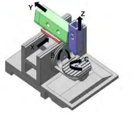
2.1 Configuration of 5-axis machine tool. 5
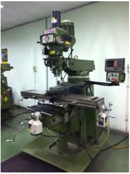
2.2 Conventional vertical milling machine 8
2.3 Conventional milling 9
2.4 Climb milling 9
2.5 Interface of CATIA V5 11
2.6 Vibration damper designed by Sun 13
2.7 Particle damper designed by Zhang 14
2.8 The smart flag-shaped damper 15
2.9 Flag-shaped system 15
2.10 Rocking vibration mode on a machine tool 16
2.11 Geometry of vibration in end milling 17
2.12 Damper designed by Xie 18
2.13 The rebound and compression piston in the damper 19 2.14 Components of the cutting force in milling toward table
dynamometer
20
2.15 Table dynamometer 21
2.16 The bottom view of table dynamometer 21
2.17 Surface roughness tester 22
x
2.19 Aluminium alloy 6061 24
2.20 Neoprene rubber sheet. 25
3.1 The process of cutting the work piece into small part 29
3.2 Finishing process of the work piece 30
3.3 Designed work piece in SolidWork 2016. 31
3.4 Set up of table dynamometer in CNC milling machine 32
3.5 Example result (Graph of Force against Time) 33
3.6 Example result (Table form) 33
3.7 Set up of parameters in DynoWare 34
3.8 Example result (Graph of Amplitude against Frequency) 35
3.9 Surface roughness tester 36
3.10 Hydraulic Shock Damper 37
3.11 Designed damper with hydraulic Shock Damper and Neoprene Rubber Sheet.
38
3.12 Actual product of the damper 38
3.13 The workpiece and damper were locked on table dynamometer 38
3.14 Design option 39
4.1 Ra value of the workpiece after milling process without Damper 41 4.2 Ra value of the workpiece after milling process with Damper 42
4.3 Graph of Force (Fx) (N) against time (s) 45
4.4 Graph of Force (Fy) (N) against time (s) 45
4.5 Graph of Force (Fz) (N) against time (s) 46
4.6 Graph of force (Fx)(N) against time (s) 48
4.7 Graph of force (Fy)(N) against time (s) 49
xi
4.9 Total average of maximum force 52
4.10 Graph of amplitude (dB) against frequency (Hz) without damper in force Fx
55
4.11 Graph of amplitude (dB) against frequency (Hz) with damper in force Fx
56
4.12 Comparison between amplitude data of the milling process without damper and the milling process with damper in force Fx
57
4.13 Graph of amplitude (dB) against frequency (Hz) without damper in force Fy
59
4.14 Graph of amplitude (dB) against frequency (Hz) with damper in force Fy
60
4.15 Comparison between amplitude data of the milling process without damper and the milling process with damper in force Fy.
61
4.16 Graph of amplitude (dB) against frequency (Hz) without damper in force Fz
63
4.17 Graph of amplitude (dB) against frequency (Hz) with damper in force Fz
64
4.18 Comparison between amplitude data of the milling process without damper and the milling process with damper in force Fz.
xii
LIST OF TABLES
TABLES TITLE PAGE
4.1 4.2 4.3 4.4 4.5 4.6 4.7 4.8 4.9 4.10 4.11 4.12 4.13
Ra value of workpiece after milling process without damper Ra value of workpiece after milling process with damper
Comparison between Ra value (μm) of the workpiece after milling process with damper and milling process without damper.
The reading of force (Fx) for workpiece that milling without damper
The reading of force (Fy) for workpiece that milling without damper
The reading of force (Fz) for workpiece that milling without damper
The reading of force (Fx) for workpiece that milling with damper The reading of force (Fy) for workpiece that milling with damper The reading of force (Fz) for workpiece that milling with damper Amplitude value of Fx in milling process without damper
Amplitude value of Fx in milling process with damper Comparison between amplitude data of the milling process without damper and the milling process with damper in force Fx. Amplitude value of Fy in milling process without damper
xiii 4.14
4.15
4.16 4.17 4.18
Amplitude value of Fy in milling process with damper Comparison between amplitude data of the milling process without damper and the milling process with damper in force Fy. Amplitude value of Fz in milling process without damper
Amplitude value of Fz in milling process with damper Comparison between amplitude data of the milling process without damper and the milling process with damper in force Fz.
60
61
xiv LIST OF ABBREVIATION, SYMBOLS AND
NOMENCLATURE
CNC - Computer Numerical Method CAD - Computer Aided Design
CAM - Computer Aided Manufacturing
ASTM - American Society for Testing and Materials
µm - micrometre or micron
m - millimetre
cm - centimetre
s - second
kN - kilonewton
% - percent
1 CHAPTER 1
INTRODUCTION
1.1 Background
Vibration deteriorate the accuracy and productivity of precision machine tools and product. Basically, vibration is caused by axial movement and the vibration of the entire machine. The fluctuation in cutting force throughout clipping of chip and the existence of frictional force within the tool and the workpiece create the vibration even greater. However, the tool life may be affected if the vibration continuously occurs. Also, it leads to get poor surface finishing of the final product. Therefore, vibration in milling operation should be reduced. There are many methods to measure and predict vibration, identifying the dynamics of the structure, and the main important specification like ordinary frequency, damping ratio and use equations that model the dynamics within the cutting operation and the vibration of the structure is the traditional method.
2 Table Dynamometer is the device to measure the vibration form the cutting tool toward the work piece, based on the data obtained such as cutting force and amplitude, the vibration could be determined. This device is put on the work space of CNC machine and beneath the work piece before the machining begin. Then, DynoWare is used to run and obtain the data. The result is clear and obvious as it is in graph form, showing the force against time on each single axis. Moreover, surface roughness of the workpiece will be measured by using surface roughness tester as an extra data to determine the vibration. By comparing the results which is one without damper and with the designed damper, the vibration could be determined.
1.2 Problem Statement
CNC machine performs precision machining of complex features in automotive and aerospace industry with strict quality requirement. The features of multi-axis cutting and various of cutting tools bring advantages to the operator to produce quality product in shorter time. However, there are still some limitation that happen when on the machining of CNC, vibration is the problem that usually faced and cannot be avoided, either it is in cutting cool itself or towards the work piece, especially the milling process. When the process is running, the force from X-axis, Y-axis, and Z-axis are generated toward work piece, making the work piece vibrates. Otherwise, the cutting tool vibrates itself as it is undergoing high speed turning. The higher speed the turning speed, the higher the vibration occurred.
3 1.3 Objectives
There are 3 objectives of this project which are:
i. To reduce the vibration in milling operation ii. To improve chatter stability in milling machine
iii. To generate smooth and good surface finish of the product
1.4 Scope
This project scope consists of:
i. Design and develop a damper to reduce vibration in milling operation. ii. Measure the cutting force and amplitude by using table dynamometer and
DynoWare.
iii. Measure the surface roughness of the work piece by using surface roughness tester
iv. Compare the result of the measurement with and without damper.
1.5 Significant of Study
4 1.6 Expected Results
5 CHAPTER 2
LITERATURE REVIEW
2.1 Five-Axes Simultaneous CNC Milling Machine
Standard five-axes CNC milling machine should have linear motion along the X, Y, and Z axes which are the translational axes. There are also the additional rotational axes which are A, B, and C axes. The mechanical components of the CNC machine will move along or around the stated axes to perform machining process.
[image:21.595.200.414.512.698.2]According to Bologa et al. (2016) CNC (Computer Numerically Controlled) machine-tools are the most critical technological equipment in the sector of metal-cutting and machine building industry. the machine slides are moving on complex trajectories to develop the configuration of the machined part. Computer numerically controlled closed-loop systems are the essence components of these category of machines. Figure 2.1 shows the basic configuration of the 5-axis CNC machine.
6 Huge amount of shapes is allowed the user to be machined with the combination of the simultaneous movements on the three translational axes (X, Y, and Z). On the other hand, the additional one or two rotational axes (A, B, and C) act as the extra axes combining the translational axes can be used to machine more complicated shapes like spiral surfaces and aerospace part such as turbine blades. In figure 1, X, Y, and Z are the translational axes while A, B, and C are the rotational axes rotating around X, Y, and Z respectively.
There are many advantages that CNC machines could bring to the industry. For example, the autonomous machining of CNC obviously eliminates human error and improve accuracy. Furthermore, CNC machines can work around-the-clock daily and only stop for maintenance if needed. High production and scalability can be achieved as the CNC machines executes huge quantities and affords flexible scalability after the design and specification have been entered into machines. Moreover, CNC machines provide safer environment directly toward the operator, there is always a distance from the sharp tools from the operator. However, Operator required specified skill to run the machines.
In 2014, Feng et al. published a paper in which they described five-axis CNC system can regulate three linear axes and two rotary axes to move at the same time. The cutter’s position and direction can be resolved at the same time, hence the cutter can better adapt to the workpiece surface. With the asset such as lesser machining time, greater machining accuracy and less number of fixtures, five-axes milling is generally used to machine impellers and structural parts in aeronautics and space industry.
7 under the machine coordinate system. With such function, the CNC system can undoubtedly reimburse the rotary movements in actual-time. (Feng et al., 2014).
Similarly, Nojehdah et al. (2016) also found that five-axis CNC machine tool execute precision machining of complicated features in automotive, aerospace and power generation industries to cope with strict quality compulsion. It is stated that improper attainment of rotary axes extremely disturbs useful accuracy of machined features and increase complexity of root cause analysis. This problem may convince pricey blunder in machine tool repair or trouble-shooting tasks.
2.2 Conventional Milling Machine
In industry, from a small factory to a big company, a vertical milling machine is widely used. Milling machines has evolved so much from the pass, it can be found before the world war one, there are a lot of firms built milling machines all along. However, with the change of time, Computers and CNC machine tools continue to establish briskly, the
need for a manual milling machine was affected.
The spindle axis is vertically oriented in the vertical mill, the cutting tools are gripped
in the spindle and rotate on its axis. The spindle can commonly be extended, making the
cutting and drilling process. There are two types of vertical milling, which are the bed mill
and the turret mill. There is a stationary spindle in a turret mill and the table is allowed to
move both perpendicular and parallel to the spindle axis to accomplish cutting. Bridgeport
is the most common example. Also, there is always a quill equipped in turret mills which
allows the cutting tools to be raised and lowered in a manner like a drill press. This type of
machine offers two methods of cutting in vertical (z) direction: by raising or lowering the
quill and by moving the knee. However, in the bed mill, the table moves only perpendicular
to the spindle’s axis while the spindle itself moves parallel to its own axis. Figure 2.2 showed
8 Figure 2.2: Conventional vertical milling machine
There are two distinct ways to cut materials, which are conventional milling and
climb milling. The main contrast between both two techniques is the connection of the
rotation of the cutter to the direction of feed. The cutter rotates against the direction of the
feed in conventional milling which during the climb milling process, the cutter rotates with
the feed. Backlash become the main reason for the traditional approach of conventional
milling as the elimination of the lead screw and the nut in machine. However, climb milling
has recently been identified as the favoured way to access a workpiece because there are