Int. J. Electrochem. Sci., 10 (2015) 5036 - 5047
International Journal of
ELECTROCHEMICAL
SCIENCE
www.electrochemsci.orgEffects of Ellipsoidal Corrosion Defects on Failure Pressure of
Corroded Pipelines Based on Finite Element Analysis
J. Zhang*, Z. Liang*, C.J. Han
School of Mechatronic Engineering, Southwest Petroleum University, Chengdu, 610500, China
*
E-mail: [email protected]; [email protected]
Received: 12 March 2015 / Accepted: 9 April 2015 / Published: 28 April 2015
Failure pressures of corroded pipeline with single-point and multi-point corrosion pit were investigated by finite element method in this paper. Effects of internal pressure, length, depth and spacing of corrosion pits on failure pressure of corroded pipeline were discussed. The results show that no matter for axial corrosion pit or ring corrosion pit, the maximum stress appears on the bottom of single-point corrosion pit along pipeline axis direction, and the minimum stress appears on the end along pipeline ring direction. Von Mises stress and plastic strain increase with the increasing of internal pressure. Failure pressure of corroded pipeline decreases with the increasing of corrosion pit depth, but it increases with the increasing of wall thickness. With the increasing of corrosion pit length, failure pressure of corroded pipeline with axial corrosion pit decreases, while it increases for ring corrosion pit. Corroded pipeline with multi-point corrosion pit is more prone to failure than with single-point corrosion pit. For multi-point corrosion pit, with the increasing of internal pressure, the maximum plastic strain first appears on one end of the ellipsoidal corrosion pit and then on the bottom. Failure pressure of corroded pipeline increases gradually with the spacing increases.
Keywords: corroded pipeline, corrosion defect, failure pressure, finite element analysis, corrosion pit morphology
1. INTRODUCTION
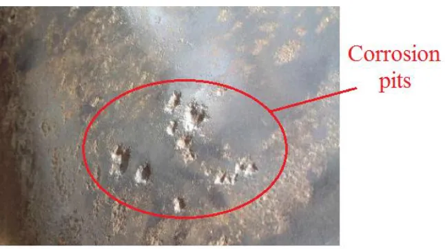
electrolyte. Then the corrosion cell is formed, and REDOX reaction was performed. Under the action of geological, soil and high pressure medium, corrosion pits appear on both inner and outer walls of the pipeline, as shown in Fig.1. With the perforation of these corrosion pits or crack propagation, rupture accidents may occur. Leak accidents of oil and gas not only cause a large number of casualties accidents, but also result in economic loss and environmental pollution[1]. For example, in July 2011, crude oil pipeline explosion of Dalian international transportation co., LTD. caused widespread fire and a large number of oil spill, meanwhile a lot of pipeline equipment was damaged and the sea was polluted[2]. In November 2013, rupture accident of Huang-Wei pipeline happened, which caused a large number of oil leakage, and the oil spilled into the rainwater pipeline. Manu roads and motor vehicles were dynamited in this accident. And 52 people were killed, 11 people missing. After pipeline corrosion, global or local thinning of the wall thickness would reduce the static and dynamic strength of pipeline. So, corrosion is the primary factor of failure accident for long distance oil and gas pipelines. Therefore, it is very important to study the residual strength of pipeline for its safety evaluation and operation.
In the 1970s, ASME-B31G was used to calculate the failure pressure of corroded pipeline by American society of mechanical engineers[3]. At the beginning of the 21st century, DNV RP-F101 was put forward to appraisal corroded pipeline by DNY and BG based on full-scale experiment and finite element analysis[4]. According to the blasting experiment and numerical simulation, a computational formula of failure pressure was proposed by Choi. This computational formula is suitable for X65 pipeline[5]. Based on MB13G method, EPA method was proposed by Freire according to blasting limit experiment[6]. Recent years, Chen studied the interaction relationship for submarine pipeline with axial corrosion defects [7]. Shuai predicted the failure pressure of corroded pipeline by finite element method, and fitted a prediction formula[8]. But the discussion of effects of multi-point corrosion pits on failure pressure is very little. In this paper, corroded pipelines with a single corrosion pit and multi-point corrosion pits were investigated by using finite element method, and effects of the length, width and spacing of corrosion pits on failure pressure were discussed.
[image:2.596.136.459.536.717.2]
2. MATERIALS AND METHODS 2.1 Material model
Material hardening has a great effect on the blasting failure of the pipeline. So, in order to reflect the hardening properties after material yield, Ramberg-Osgood stress-strain rule was used in this model [8].
n
s
s
0 (1)
Where, 0is initial strain, 0s E. sis yield stress, MPa. E is elasticity modulus, MPa. is the hardening coefficient. n is power hardening exponent.
2.2 Failure criteria of pipeline
There are three kinds of failure criteria for the numerical simulation of corroded pipeline. The first one is the elastic limit criterion[9]. The pipeline is prone to failure if von Mises stress of corrosion area is bigger than the yield stress of the material. The second one is failure criterion based on plastic limit state[10]. Failure of corroded pipeline can be determined by hoop stress of corrosion area. When the hoop stress reaches the tensile strength, pipeline failure occurs. The third one is plastic failure criterion[11]. When the minimum equivalent stress is bigger than the ensile strength, failure occurs. In this paper, the reason why the elastic limit criterion is replaced by plastic failure criterion is its conservative, and von Mises stress is regarded as the minimum equivalent [12].
2 1 2 2 1 2 2 1 2 2 1 2 1 v (2)Where, vis von Mises stress, MPa.
is the allowable stress, MPa. According to ASME B31G-2009 [13], the failure pressure is[14]: M t d t d D t Pf 1 85 . 0 1 85 . 0 1 2 (3)
Where, Pf is failure pressure of the pipeline, MPa. D is outer diameter of the pipeline, mm. t is wall thickness of the pipeline, mm. d is the depth of the corrosion pit, mm. M is Folias expansion coefficient. is the flow stress, MPa.
95 . 68
s
(4) 50 , 00337 . 0 6275 . 0 1 2 4 2 Dt l Dt l Dt l M (5) 50 , 3 . 3 032 . 0 2 2 Dt l Dt l M (6)
3. EFFECT OF SINGLE-POINT CORROSION PIT 3.1 Numerical simulation model
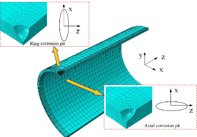
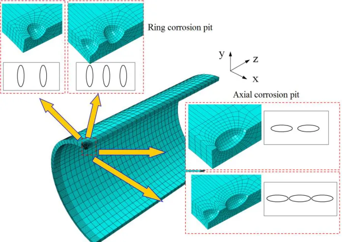
The structural response of steel pipeline is examined numerically using advanced computational tools[15]. An advanced general purpose finite element program ABAQUS is employed to simulate the mechanical behavior of buried pipeline under internal pressure. In this paper, ellipsoidal corrosion pits are considered. Finite element model of 1/4 pipeline was established for the symmetry of structure and load. As shown in Fig.2, eight-node solid elements are employed to model the pipeline[16]. Diameter of the pipeline is 324mm, wall thickness of the pipeline is 10.6mm. In order to eliminate the edge effect, length of the pipeline is 3 times the diameter.
A linear isotropic strain hardening model has been considered in the plasticity model of the steel pipeline material[17]. The correlation yield function is dependent on the equivalent pressure stress. This model has been used with a von Mises yield surface criterion[18]. Numerical results are obtained for X65 steel pipeline. Yield stress is 448.5MPa, tensile strength is 531MPa, Young's modulus is 206 GPa, Poisson's ratio is 0.3, density is 7800kg/m3[19]. The axial and ring corrosion pits were considered in this paper. The end of the pipeline was fixed along z direction. Then three symmetry planes were imposed symmetry constraints along x, y, z directions respectively. Internal pressure was applied on the internal wall of the pipeline.
Figure 2. Finite element model of a single corrosion pit
[image:4.596.134.461.408.636.2]
3.2 Simulation results
When length of the corrosion pit is 15mm, depth is 5mm, von Mises stress distributions around the pit under different internal pressure are shown in Fig.3. No matter the axial corrosion pit or ring corrosion pit, the maximum stress appears on the bottom of the corrosion pit along pipeline axis direction. The minimum stress appears on the ends along pipeline ring direction. Von Mises stress increases with the increasing of internal pressure. When the stress is bigger than the yield limit, stress of the whole pipeline increases rapidly. Then pipeline explosion occurs when the internal pressure is bigger than failure pressure [12].
Figure 3.Von Mises stress distribution around the pit under different pressures
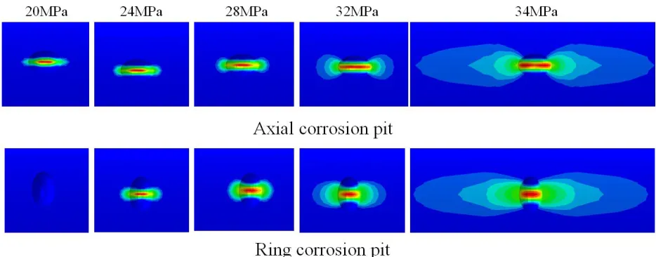
[image:5.596.91.505.230.417.2]Plastic strain distributions around the pit under different pressures are shown in Fig.4. Under the same pressure, plastic strain with bar-type appears on the pipeline with axial corrosion pit. Plastic area increases with the increasing of internal pressure. The maximum plastic strain appears on the bottom of the corrosion pit.
[image:5.596.64.531.568.751.2]
Table 1 shows the failure pressures of the two corrosion pits by simulation and ASME B31G [13]. When the length of corrosion pit is 15mm, depth is 3mm, the failure pressures of corroded pipeline with ring corrosion pit obtained by simulation ASME B31G are the same. It means that the numerical simulation method in this paper is reliable, and it can be used to predict the failure pressure of corroded pipeline. The failure pressure of ring corrosion pit is more than axial corrosion pit to close to the results calculated by ASME B31G. So, ASME B31G can be used to predict the failure pressure corroded pipeline with ring corrosion pit, but not suitable for axial corrosion pit.
[image:6.596.73.527.324.427.2]Failure pressure of axial corrosion pit is smaller than the ring corrosion pit. It means that the pipeline with axial corrosion pit is prone to failure under the same volume defects. When the length is 15mm, difference between the two failure pressures is 5.6MPa. When the length of the pipeline is 19mm, the difference is 8.9MPa. Therefore, wall thickness, length and depth of corrosion pit have a great effect on the failure pressure of corroded pipeline [20].
Table 1. Failure pressures of pipeline by simulation and ASME B31G (Unit, MPa)
Wall
thickness(mm)
Length (mm)
Depth (mm)
Corrosion pit
ASME B31G
Axial Ring
10.6 15 3 23.82 33.65 33.65
10.6 15 4 21.84 29.82 33.54
10.6 15 5 20.53 26.13 33.41
10.6 19 5 18.52 27.42 33.16
14.3 15 5 33.18 39.35 45.39
3.3 Depth of the corrosion pit
When length of corrosion pit is 15mm, Fig.5 shows failure pressures of corroded pipeline under different pit depths. Failure pressure of corroded pipeline decreases with the increasing of corrosion pit depth with nonlinear rule. When the corrosion pit depth is smaller, the failure pressure difference between axial corrosion pit and ring corrosion pit is bigger. But it decreases with the increasing of corrosion pit depth. When the pit depth is 7.5mm, the corrosion pit is a half spherical. So, failure pressures of the two corroded pipeline are the same.
[image:6.596.196.399.599.750.2]
3.4 Length of the corrosion pit
[image:7.596.175.422.216.400.2]When depth of corrosion pit is 5mm, failure pressures of corroded pipeline under different pit lengths are shown in Fig.6. When length of the corrosion pit is 5mm, the pit becomes a half spherical. So, failure pressures of corroded pipeline with axial corrosion pit and ring corrosion pit are the same. With the increasing of length of corrosion pit, failure pressure of corroded pipeline with axial corrosion pit decreases, while it increases for the corroded pipeline with ring corrosion pit. But the change rate decreases also.
Figure 6. Failure pressure of corroded pipeline under different pit lengths
3.5 Wall thickness of the pipeline
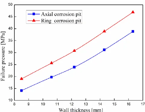
Figure 7. Failure pressure of corroded pipeline under different wall thicknesses
[image:7.596.177.417.495.681.2]
15mm, depth is 5mm, failure pressures of corroded pipeline under different wall thicknesses are shown in Fig.7. With the increasing of wall thickness, failure pressure of corroded pipeline increases. Therefore, thick wall pipeline should be used in severely corrosive environment.
4. EFFECT OF MULTIPLE CORROSION PITS
4.1 Numerical simulation models
Multi-point corrosion is more often than single point corrosion in engineering practice [21]. The interaction between corrosion pits should not be ignored. Finite element models of double-point and three-point corrosion pit were established as shown in Fig.8. Boundary conditions and loads are the same as Fig.2.
4.2 Simulation results
[image:8.596.125.473.459.705.2]When the initial spacing is 5mm, length and depth of the corrosion pit are 15mm and 5mm, failure pressures of corroded pipeline with two kinds corrosion pits are shown in Fig.9. Under multi-point corrosion pit condition, failure pressure of corroded pipeline with axial corrosion pit is smaller than ring corrosion pit. Failure pressure of corroded pipeline with multi-point corrosion pit is smaller than single-point one. But the difference between double-point and three-point corrosion pits is small. So, multi-point corrosion pit model can more accurately predict failure pressure of the pipeline.
Figure 9. Failure pressure under different corrosion pit number
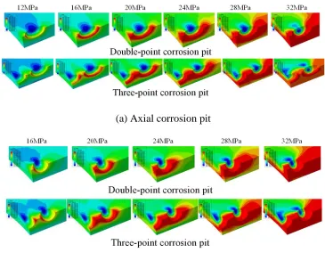
Fig.10 shows the von Mises stress distribution around multipoint corrosion pit. With the increasing of internal pressure, high stress area increases gradually. Before plastic strain appears, von Mises stress distribution of corroded pipeline changes little. In the elastic stage, failure pressures of double-point and three-point axial corrosion pits are 14.6MPa and 14MPa. While failure pressures of double-point and three-point ring corrosion pits are 19.2MPa and 18.3MPa. Under the same internal pressure, high stress area of three-point corrosion pit is bigger than double-point corrosion pit, high stress area of axial corrosion pit is bigger than ring corrosion pit.
(a) Axial corrosion pit
(b) Ring corrosion pit
[image:9.596.181.411.71.251.2] [image:9.596.115.480.422.715.2][image:10.596.59.538.68.237.2]
(a) Axial corrosion pit (b) Ring corrosion pit Figure 11. Plastic strain around multipoint corrosion pit
Fig.11 shows plastic strain around multipoint corrosion pit. For double-point corrosion pit, plastic strain first appears on one end of the ellipsoidal corrosion pit when internal pressure is small. Plastic area increases with the increasing of internal pressure along pipeline axis direction, and the maximum plastic strain appears on the bottom of the pit. But the width of plastic area of ring corrosion pit is bigger than axial corrosion pit. When internal pressure is more than 32MPa, plastic area sharp increases. For three-point corrosion pit, the plastic area is bigger than double-point corrosion pit. Plastic strain of the side corrosion pit is bigger than the middle one. So, location of corrosion pit is prone to failure for the pressure pipeline.
4.3 Spacing of corrosion pits
(a)Double-point corrosion pit (b) Three-point corrosion pit
Figure 12. Failure pressure of corroded pipeline with multipoint corrosion pit under different spacing
[image:10.596.59.543.468.672.2]
corroded pipeline changes small when the spacing is more than 17mm. But for three-point axial corrosion pit, the critical spacing is 20mm. So, effect of the interaction between corrosion pits on failure pressure decreases with the spacing increases. Intensive corrosion pit distribution could increase the pipeline failure probability [17].
5. CONCLUSIONS
1. No matter for axial corrosion pit or ring corrosion pit, the maximum stress appears on the bottom of single-point corrosion pit along pipeline axis direction. The minimum stress appears on the ends along ring direction of the pipeline. Von Mises stress and plastic strain increase with the increasing of internal pressure. The maximum plastic strain appears on the bottom of the pit.
2. Failure pressure of corroded pipeline decreases with the increasing of corrosion pit depth, but it increases with the increasing of wall thickness. With the increasing of corrosion pit length, failure pressure of corroded pipeline with axial corrosion pit decreases, while it increases for the corroded pipeline with ring corrosion pit.
3. Failure pressure of corroded pipeline with multi-point corrosion pit is smaller than the single-point. Under the same internal pressure, high stress area of three-point corrosion pit is bigger than double-point corrosion pit, high stress area of axial corrosion pit is bigger than ring corrosion pit. For multi-point corrosion pit, the maximum plastic strain first appears on one end of the ellipsoidal corrosion pit then on the bottom of the pit with the increasing of internal pressure. With the increasing of the spacing, failure pressure of corroded pipeline increases gradually, but the change rate decreases.
ACKNOWLEDGEMENTS
This research work was supported by the National Natural Science Foundation of China (51474180)
References
1. B. Cai, Research on the impact of corroded to the ultimate load capacity of pipeline, Shenyang University of Technology, Shenyang (2014)
2. Q. D. Bai, Residual strength study of corroded pipeline, Daqing petroleum institute, Daqing (2006) 3. ASME-B31G, America Society of Mechanic Engineering, USA (1991)
4. DNV-RF-F101, Det Norske Veritas, Norway (2004)
5. J. B. Choi, B. K. Goo and J. C. Kim, International Journal of Pressure Vessels and Piping, 80 (2003)121-128
6. J. L. F. Freire, R. D. Vieira and J. T. P. Castro, Experimental Techniques, 30(6) (2006) 60-65 7. Y. F. Chen, X. Li, J. Zhou and J. Guan, China Ocean Engineering, 22 (2008) 359-370 8. J. Shuai, C. E. Zhang and F. L. Chen, Acta Petrolei Sinica, 29 (2008) 933-937
9. Y. S. Wang, Proceedings of the International Conference on Offshore Mechanics and Arctic Engineering (10th), Stavanger, Norway, (1991) 23-29
10.P. Hopkins and D. G. Jones, Proceedings of the 11th International Conference of Mechanic and Arctic Engineering, Calgary, Canada, (1992)7-11
13.Z. X. Chen, M. Wu and M. M. Cheng, Materials Protection, 47(5) (2014) 34-36 14.ASME B31G-2009, American Society of Mechanical Engineers, USA (2009) 15.Y. Q. Wang, W. B. Wang and Q. S. Fang, Corrosion Protection, 29(1) (2008) 28-31
16.J. Zhang, Z. Liang and C. J. Han, Journal of Natural Gas Science and Engineering, 21(2014) 921-928
17.J. Zhang, Z. Liang and C. J. Han,Journal of Failure Analysis and Prevention, 14(2014) 530-536 18.P. Vazouras, S. A. Karamanos and P. Dakoulas, Soil Dynamic and Earthquake Engineering, 30
(2010) 1361-1376
19.J. Zhang, Z. Liang and C. J. Han,Strength, Fracture and Complexity, 8(2013/2014) 179–188 20.B. Ma, J. Shuai, D. Liu and K Xu, Engineering Failure Analysis, 32 (2013) 209-219
21.B. Keshtegar, M. Miri, Engineering Failure Analysis, 46 (2014) 104-117