Link Level Modelling Techniques for Analysing the Configuration of Link
Adaptation Algorithms in Mobile Radio Networks
Javier Gozalvez* and John Dunlop**
*Now with the Signal Theory and Communications Division at the University Miguel Hernández of Elche (Spain), previously at the University of Strathclyde
**Mobile Communications Group, EEE Dept, University of Strathclyde 204 George St, Glasgow G11XW, Scotland
[email protected], [email protected]
Abstract: The operation of Link Adaptation
algorithms is based on channel quality estimates. It is therefore important to analyse the performance of such algorithms with link level models that properly capture the channel conditions and dynamics. Previous research [1] concluded that the use of simple link level models does not give an accurate prediction of the estimated performance of Link Adaptation algorithms. Following this previous work, this paper shows that the link level model considered for the study of Link Adaptation algorithms can also influence the decisions regarding the optimum configuration of the algorithm.
1. Introduction
The increasing demand for traditional and new mobile communication services and the limited available bandwidth requires the design and implementation of advanced techniques that efficiently use the scarce radio resources [2]. Link Adaptation seeks to achieve this objective by adaptively selecting a suitable transport mode, according to a predefined criteria, that is optimised for the experienced channel quality conditions. Although Link Adaptation (LA) was initially proposed for 3G systems, it has been recently considered for the evolution of both 2G and 3G systems. In fact, LA is a key technology for the Adaptive Multi-Rate codec (AMR), General Packet Radio Services (GPRS), Enhanced Data rates for GSM Evolution (EDGE) and High-Speed Downlink Packet Access (HSDPA) systems.
The performance evaluation of a cellular system is usually conducted at two different levels: system level and link level. While the former models a mobile radio network, the later models the radio link at the bit level. Link-to-system level interfaces are hence necessary to study the overall performance. Different levels of accuracy in the representation of transmission errors and in the representation of the inherent variability present in the radio channel can be targeted with such interfaces, depending on the particular study carried out at the system level. System level studies, including many concerning the performance of LA algorithms, are usually based on simple link-to-system level
interfaces that model errors at the block level and do not include fast fading at the system level. Different studies (e.g. [3], [4] and [5]) have proposed new link-to-system level interfaces that improve the accuracy in the representation of the link level behaviour. The study presented in [6] evaluated the capacity of an EDGE system considering an accurate link-to-system level interface based in [4]. The authors conclude that, although in terms of capacity their results were similar to those presented in [7], where a simple link-to-system level interface was used, improved interfaces should be considered since they allow a more accurate modelling of link quality control schemes (such as Link Adaptation).
link-to-system level interface used may have an effect on the predicted dynamics of the LA updating periods and therefore on the decisions about how to configure the LA algorithm to maximise the system performance.
2. General Packet Radio Services
This study has been conducted for packet data transmissions in a GPRS-like system. The GPRS radio interface can be modelled as a hierarchy of logical layers with specific functions [10]. This work focuses on the RLC/MAC and physical layers.
Prior to transmission, data packets are segmented into smaller data blocks across the different layers, with the final logical unit being the Radio Link Control (RLC) block. The resulting RLC data blocks are then coded and block-interleaved over four normal bursts in consecutive TDMA frames. The RLC block’s data field length will depend on the particular Coding Scheme (CS) used.
The GPRS standard defines four different coding schemes; their main characteristics are shown in Table 1. These four coding schemes offer a trade-off between throughput and coding protection, paving the way for the application of dynamic LA to GPRS.
Scheme Code rate Payload Data rate (kbits/s)
CS1 1/2 181 9.05
CS2 ≈2/3 268 13.4
CS3 ≈3/4 312 15.6
[image:2.595.311.533.54.160.2]CS4 1 428 21.4
Table 1: GPRS coding scheme characteristics
3. Simulation Tools
This section presents the link and system level simulation tools developed and used to conduct this research. The different interfaces considered between these two levels will be described in section 4.
3.1. Link Level Simulation Tool
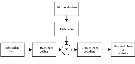
The link level tool, described in full detail in [11], has been used to produce the different link-to-system level interfaces necessary for the assessment of LA in a packet-switched environment. The tool, illustrated in Figure 1, models the full GPRS transmission chain by means of a C++ simulator that implements the GPRS coding schemes and models the radio transmission errors by means of a database of error patterns. These error patterns were previously obtained with the bit level simulation package COSSAP. The main benefit of this simulation approach is that it significantly reduces the simulation time whilst maintaining the accuracy of the radio link quality representation [11].
Received blocks & statistics
X GPRS channeldecoding
GPRS channel coding Information
bits
Bit Error database
Deinterleaver
Figure 1: GPRS link level simulator
The link level simulations have been conducted for a typical urban channel model and under an interference-limited environment following ETSI recommendations [12].
3.2. System Level Simulation Tool
The system level analysis has been conducted using an event-driven simulator working at the burst level [8]. The time-scale resolution considered ensures a high modelling accuracy and allows to account for sudden channel quality variations. The system level simulator models the channel quality in terms of the Carrier to Interference Ratio (CIR). To calculate the CIR, the simulator considers the first and second tier of co-channel interferers. The pathloss is predicted using the Okumura-Hata model. Although this model was based on measurements done for distances greater than 1km, the model can be extended for distances below 1km [13]. The shadowing has a log normal distribution with a standard deviation of 6dB and a decorrelation distance of 20 meters.
The simulation tool models a cellular network of equally sized 3-sector macro cells, with a cluster size equal to four. Each cell has a radius of 1km and each sector has been assigned two carriers. Although mobility has been implemented, handover between sectors has not been considered. As a result, mobile stations are connected to the closest base station and not to the best serving base station. The boundary effects have been removed by using a wrap-around technique.
[image:2.595.62.285.374.461.2]following the GPRS specifications. A perfect feedback of the ARQ report with no RLC block loses has been assumed.
4. Link-to-System Level Interfaces
As previously mentioned, the study of a cellular system is usually performed at two different levels: system and link level. The reason for this separation is the high computational requirements generally associated with the link level analysis. Usual procedures to interface both levels are to use the link level analysis as a source of information for the system level. The link level performance is then represented by a simplified model consisting of a set of look-up tables mapping the CIR to a given link quality parameter such as the BLER. Different levels of accuracy can be targeted with the look-up tables depending on the particular study carried out at the system level. For this work, two different types of link-to-system level interfaces, each with a different degree of accuracy, have been produced.
The first approach, generally used in the literature for system level investigations (e.g. in [9]), works at the RLC block level and will therefore be referred in the rest of this paper as block level modelling. This approach maps the mean CIR experienced over the four bursts used to transmit a RLC block to the final block quality measure, e.g. BLER. An example of this type of LUT is illustrated in Figure 2, for all GPRS coding schemes, a speed of 50km/h and without considering the use of frequency hopping.
1e-006 1e-005 0.0001 0.001 0.01 0.1 1
0 5 10 15 20
BLER
C/I
BLER vs C/I for TU50 without FH
[image:3.595.314.534.359.520.2]CS1 CS2 CS3 CS4 ref performance
Figure 2: Block level modelling LUT (BLER vs C/I in dB)
The combined effects of convolutional coding and interleaving make the block errors dependent not only on the mean block quality but also on the quality distribution among the four bursts used to transmit a RLC block. To accurately model block errors, a more sophisticated approach modeling the link level performance at the burst level has been considered. This second approach, based in [3], will be referred in the rest of this paper as burst level modelling. The burst level interface is composed of two sets of LUTs.
The interface requires as input from the system level the mean CIR experienced in a given burst. This mean CIR value takes into account the pathloss,
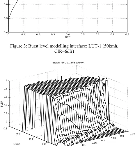
shadowing and interference relationships in the system. The first interface (LUT-1) extracts the burst link quality, represented by means of the Bit Error Rate (BER), for the measured burst CIR. As illustrated in Figure 3, this interface is represented as a cumulative distribution function (cdf) of the BER for a given CIR. As a consequence, there will be a burst quality cdf for each local mean CIR. A random process is then used to generate the actual BER from the corresponding cdf. The random procedure allows modelling the effect of fast fading on the BER, thereby including the fast fading at the system level, since in fact we can obtain different BER values for the same mean CIR. The BER is then estimated for the four bursts used to transmit a RLC block and a second interface (LUT-2) maps the mean BER and the standard deviation of the BER over the four bursts to a corresponding BLER value. Figure 4 shows an example of LUT-2 for CS1, a speed of 50km/h and without considering the use of frequency hopping. The BLER varies between 0 and 1. Negative values have been used to differentiate the case where the BLER is equal to 0 and the case where a given combination of a mean and standard deviation of burst quality never occurred in the link level simulations.
0 0.1 0.2 0.3 0.4 0.5 0.6 0.7 0.8
0.4 0.5 0.6 0.7 0.8 0.9 1
BER
P(BER<x)
BER cdf for CIR=6dB
Figure 3: Burst level modelling interface: LUT-1 (50kmh, CIR=6dB)
0 0.05
0.1 0.15
0.2 0.25
0.3 0.35
0 0.2 0.4 0.6 0.8
0 0.2 0.4 0.6 0.8 1
Standard deviation BLER for CS1 and 50km/h
Mean
[image:3.595.312.544.453.705.2]BLER
[image:3.595.63.283.455.606.2]5. Link Adaptation Algorithm
As already discussed, the basis of LA is to assess the channel conditions and then use a CS that is optimised for these conditions, according to a predefined criteria. Since this work is based on non-real time data services, a CS is considered to be optimum if it maximises the throughput. The criterion here considered for selecting a particular coding scheme was also proposed in [14] for the study of the EDGE performance. The throughput is defined as follows:
Throughput = RCS× (1 – BLERCS) (1)
with RCS and BLERCS being the data rate and BLER for
a given CS.
The LA switching thresholds define the boundaries between the regions where each CS maximises the throughput. Since the throughput is defined as a function of the BLER in equation (1), the representation of these boundaries depends on the modelling approach used to represent the link level performance. For the block level modelling approach, the switching thresholds are obtained using the LUTs illustrated in Figure 2 and equation (1) for all the GPRS coding schemes. As a result, each LA switching threshold is represented by a single point corresponding to a given value of the mean CIR [1]. On the other hand, if the burst level modelling approach is considered, the BLER does not depend anymore only on the mean burst quality but also on the standard deviation of the burst quality. Consequently, using equation (1) and the type of LUT illustrated in Figure 4, for all GPRS coding schemes, the LA switching thresholds are defined in this case as a collection of points, each representing a combination of mean and standard deviation of burst quality values [1].
The LA algorithm uses the quality measurements over the previous reporting period to decide on the optimum CS. The mean burst quality and the standard deviation of the burst quality over a block for each transmitted block during the last reporting period is filtered to get the quality measurements necessary for the LA algorithm. A filter with a rectangular shape has been applied throughout. In this work, a fixed initial coding scheme, CS4, has been selected at the beginning of each new data transmission.
Although the current GPRS standard does not contemplate CS changes for retransmissions, it has been considered here so that results are not conditioned by GPRS limitations.
6. Simulation Results
6.1. Performance Metrics and Evaluation Scenarios
The study presented in this paper only considers the downlink performance. The results presented in this paper correspond to a load of 16 users per sector, which represents an average bandwidth occupancy of
45%, users receiving WWW traffic and a mobile speed of 50km/h. Four different LA updating periods have been considered: 20ms, 60ms, 100ms and 200ms. An updating period of 20ms is the shortest possible one since it corresponds to the transmission time of a single RLC block in the GPRS standard.
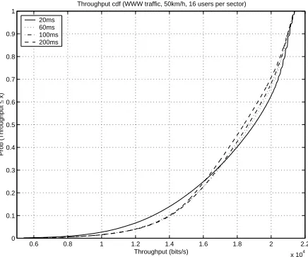
As it has been previously explained, the aim of the LA algorithm implemented for this work is to maximise the system throughput performance. As a result, one of the main performance metrics considered is the cdf of the throughput. The cdf of the throughput allows the assessment of the performance of an LA algorithm for the whole range of bit rates. The throughput is measured per user and is defined as the total number of bits successfully transmitted over the air interface divided by the radio transmission time: the throughput is measured over intervals of four seconds whenever the user is active. The throughput is collected for all users in the centre cell and the cdf of the throughput is therefore used to provide an indication of the system performance. The cdf of the throughput is also used to extract the minimum throughput for 95% of the samples, which is a frequent performance metric employed to analyse packet switched systems. The cdf of the BLER is also of interest since it provides an indication of the operation of the LA algorithm. The BLER values are also calculated over radio transmission intervals of four seconds.
In order to ensure results with good statistical accuracy, each simulation scenario simulates the transmission of more than 30 × 106 RLC blocks in the
central cell.
6.2. Results
Figure 5 plots the throughput performance, using the block level modelling interface, for various LA updating periods. The results presented in this figure correspond to a load of 16 users per sector, a mobile speed of 50km/h and users receiving WWW traffic. Figure 6 illustrates the throughput performance for the same operating conditions as Figure 5 but this time using the burst level modelling approach to interface the link and system level studies. The direct comparison of figures 5 and 6 shows the difference in the predicted operation of LA for various LA updating periods depending on the link-to-system level interface used.
conducted using the burst level modelling approach shows that, actually, the 20ms LA updating period gives the best throughput to only a percentage of the samples and it also increases the number of samples with low bit rates. Taking into account the different modelling procedures of each type of link-to-system level interface, the burst level modelling approach represents the inherent variability present in the radio channel more accurately than the block level modelling approach. Consequently, using the burst level modelling approach provides a better indication of the true LA performance and operation. The results presented here show that the use of simple link-to-system level interfaces can also lead to inappropriate decisions with respect to the configuration of LA to maximise system performance.
0.4 0.6 0.8 1 1.2 1.4 1.6 1.8 2 2.2
x 104
0 0.1 0.2 0.3 0.4 0.5 0.6 0.7 0.8 0.9 1
Throughput cdf (WWW traffic, 50km/h, 16 users per sector, block level modelling)
Throughput (bits/s)
Prob (Throughput
≤
x)
[image:5.595.64.284.251.441.2]20ms 60ms 100ms 200ms
Figure 5: Throughput cdf using the block level modelling approach (WWW traffic, 50km/h, 16 users per sector)
0.6 0.8 1 1.2 1.4 1.6 1.8 2 2.2
x 104
0 0.1 0.2 0.3 0.4 0.5 0.6 0.7 0.8 0.9 1
Throughput cdf (WWW traffic, 50km/h, 16 users per sector)
Throughput (bits/s)
Prob (Throughput
≤
x)
20ms 60ms 100ms 200ms
Figure 6: Throughput cdf using the burst level modelling approach (WWW traffic, 50km/h, 16 users per sector)
The same observation is made if the highest minimum throughput for 95% of the samples is considered. According to the results shown in Figure 5, a study using the simple link-to-system level interface, modelling the performance only at the block level, would suggest that a 20ms LA updating period provides the highest minimum throughput for 95% of the samples. However, when considering more
realistic link-to-system level interfaces, such as the ones produced using the burst level modelling approach, the obtained results show that the 20ms LA updating period actually provides the lowest minimum throughput for 95% of the samples. A similar behaviour was also observed if the considered quality metric is the average throughput.
The effect of the link-to-system level interfaces is more apparent as the BLER performance is analysed. The analysis conducted using the burst level modelling approach, and illustrated in Figure 7, showed that the BLER experienced decreases with increasing LA updating periods. On the other hand, Figure 8 indicates that if the study is conducted using the block level modelling approach, the simulation results would give the impression that the BLER actually decreases with shorter LA updating periods. It is important to note than in this case the conclusions obtained would coincide with that presented in [9], where a link-to-system level interface based on the block level modelling approach is also used. These results clearly illustrate the importance of using accurate link-to-system level interfaces for extracting appropriate conclusions on the performance and configuration of LA algorithms from studies carried out by computer simulations.
0 0.1 0.2 0.3 0.4 0.5 0.6 0.7
0 0.1 0.2 0.3 0.4 0.5 0.6 0.7 0.8 0.9 1
BLER cdf (WWW traffic, 50km/h)
BLER
Prob (BLER
≤
x)
20ms 60ms 100ms 200ms
Figure 7: BLER cdf using the burst level modelling approach (WWW, 50km/h, 16 users)
0 0.05 0.1 0.15 0.2 0.25 0.3 0.35 0.4
0 0.1 0.2 0.3 0.4 0.5 0.6 0.7 0.8 0.9 1
BLER cdf (WWW traffic, 50km/h, 16 users per sector, block modelling)
BLER
Prob (BLER
≤
x)
[image:5.595.313.534.368.562.2]20ms 60ms 100ms 200ms
[image:5.595.66.284.473.655.2]7. Conclusions
The research presented in this paper has analysed the effect that different link-to-system level interfaces have on the study of the optimum configuration of Link Adaptation algorithms in mobile radio networks. The results obtained show that using simple link-to-system level interfaces not only fails to give an accurate prediction of the LA performance but it can also lead to the adoption of inadequate decisions about the optimum configuration of the LA algorithm in a practical system. In particular, while a study conducted using simple link-to-system level interfaces would indicate that the system performance is maximised with the shortest LA updating period, the conclusions obtained using more accurate and realistic interfaces differ. The use of these accurate interfaces actually shows that using the shortest LA updating period can degrade considerably the system performance. It can therefore be concluded that this paper has emphasised the importance of using appropriate link-to-system level interfaces to predict the performance and operation of LA algorithms.
REFERENCES
[1] J. Gozalvez and J. Dunlop, "On the Importance of Using Appropriate Link-to-System Level Interfaces for the Study of Link Adaptation", in Proceedings of the IST Mobile & Wireless Communications Summit 2003, June 2003, pp 441-445.
[2] J. Zander, "Trends in Resource Management Future Wireless Networks", in Proceedings of the IEEE Wireless Communications and Networking Conference, WCNC 2000, September 2000, pp 159-163.
[3] E. Malkamäki et al, “A two-step look-up table approach for modelling the transport part in the ATDMA Detailed Simulation Testbed”, Proceedings of the RACE Mobile Telecommunications Workshop, May 1994, pp 279-283.
[4] H. Olofsson et al., “Improved Interface between Link Level and System Level Simulations applied to GSM”, in Proceedings of ICUPC’97, October 1997, pp 78-83.
[5] J. Wigard and P. Mogensen, “A simple mapping from C/I to FER and BER for a GSM type of air-interface”, in Proceedings of PIMRC’96, October 1996, pp 78-82.
[6] A. Furuskär et al, "Capacity evaluation of the EDGE concept for enhanced data rates in GSM and TDMA/136", in Proceedings of the IEEE Vehicular Technology Conference, VTC-Spring 1999, May 1999, pp 1648 -1652.
[7] A. Furuskär et al, "System performance of EDGE, a proposal for enhanced data rates in existing digital cellular systems", in Proceedings
of the IEEE Vehicular Technology Conference, May 1998, pp 1284 -1289.
[8] J. Gozalvez and J. Dunlop, "On the Dynamics of Link Adaptation Updating Periods for Packet Switched Systems", in Proceedings of the Fourth International Symposium on Wireless Personal Multimedia Communications, WPMC2001, September 2001, pp 609-614.
[9] J. Chuang, "Improvement of Data Throughput in Wireless Packet Systems with Link Adaptation and Efficient Frequency Reuse", in Proceedings of the IEEE Vehicular Technology Conference, VTC-Spring 1999, May 1999, pp 821-826. [10] ETSI, "GSM 03.64; Overall description of the
GPRS radio interface. Stage 2", version 6.1.0, Release 1997.
[11] J. Gozalvez and J. Dunlop, "High-Speed Simulation of the GPRS Link Layer", in Proceedings of the IEEE PIMRC2000, September 2000, pp 989-993.
[12] ETSI, “GSM 05.05; Radio Transmission and reception”, version 7.1.0, Release 1998.
[13] K. Feher, "Wireless Digital Communications: Modulation and Spread Spectrum Applications", Prentice Hall, 1995.