This is a repository copy of Improving the efficiency of high-temperature electrolysis of carbon dioxide in a solid oxide cell.
White Rose Research Online URL for this paper: http://eprints.whiterose.ac.uk/150829/
Version: Accepted Version
Article:
Call, A.V., Holmes, T.D., Yanallah, K. et al. (3 more authors) (2019) Improving the efficiency of high-temperature electrolysis of carbon dioxide in a solid oxide cell. ECS Transactions, 91 (1). pp. 2623-2630. ISSN 1938-6737
https://doi.org/10.1149/09101.2623ecst
© 2019 ECS - The Electrochemical Society. This is an author-produced version of a paper subsequently published in ECS Transactions. Uploaded in accordance with the publisher's self-archiving policy.
[email protected] https://eprints.whiterose.ac.uk/
Reuse
Items deposited in White Rose Research Online are protected by copyright, with all rights reserved unless indicated otherwise. They may be downloaded and/or printed for private study, or other acts as permitted by national copyright laws. The publisher or other rights holders may allow further reproduction and re-use of the full text version. This is indicated by the licence information on the White Rose Research Online record for the item.
Takedown
If you consider content in White Rose Research Online to be in breach of UK law, please notify us by
Improving the Efficiency of High-Temperature Electrolysis of Carbon Dioxide in a Solid Oxide Cell
A. V. Calla, T. D. Holmesa,b, K. Yanallahc, P. D. Desaib, W. B. Zimmermana, and
R. H. Rothmana
a Department of Chemical and Biological Engineering, The University of Sheffield,
Sheffield, South Yorkshire S1 3JD, United Kingdom
b Perlemax Ltd, 318 Broad lane , Sheffield, S3 7HQ, United Kingdom
c Laboratory of Electrical Engineering and Plasmas, University Ibn Khaldoun, Tiaret,
Algeria
This work focuses on the development of a bespoke rig which allows for the simultaneous use of non-thermal plasmas (NTPs), oscillating gas flow via a Desai-Zimmerman Fluidic Oscillator (DZFO) and a Solid Oxide Cell (SOC) to create a highly efficient energy conversion device to facilitate the reduction of CO2 to CO.
Both fluidic oscillation and NTPs have the potential to reduce resistances in a SOC, key to furthering their commercialisation. The potential role of NTPs in improving the kinetics and efficiency of reactions relevant to CO2 reduction, such as the dissociation of
CO2, is presented. Performance improvements using a rapidly
oscillating gas flow, provided by the DZFO, to minimise concentration polarisation resistance by disrupting boundary layer formation and increasing overall efficiency are also discussed. The intersection of these technologies provide a path for a paradigm shift in the ability to convert waste CO2 into high value feedstock
using renewable energy.
Background
An increased focus on renewable technologies is necessary to meet the level of carbon emission reduction required to achieve the 2°C scenario (2DS) (1, 2, 3). Carbon containing materials are at the root of most industrial value chains and currently 90% of organic chemicals are made from fossil fuels and 5-10% of global crude oil demand is for the manufacture of chemicals (1, 2). By providing a process to convert waste CO2 into
high value CO we can take steps towards the goal of reducing emissions and provide an important link between various sectors to turn waste materials into new products, improving resource efficiencies, and reducing negative environmental factors. This presents a significant opportunity to leverage CO2 as a feedstock while supporting global
goals in green energy, manufacturing, etc.
Solid Oxide Cells (SOCs), whether operated in fuel cell (SOFC) or electrolysis (SOEC) mode, are regarded as a leading technology for future clean power generation and chemical production due to their high efficiencies, fuel flexibility and long projected lifetimes (4). Excess renewable energy produced during off-peak times can be utilised to cheaply reduce a variety of feedstocks, such as CO2 and H2O, which can then be further
efficiencies of SOCs are around 50% and can be increased to 80% when used in combination with recycled heat from other high temperature systems (4). At present, over 80% of the cost to co-electrolyse CO2 and H2O comes from electrical input
necessary to drive a SOEC (5). While changes in cell geometry and composition have been used to improve performance, limitations from factors such as activation and concentration polarisation need to be addressed to advance the field further.
For widespread commercialisation to be realised, energy inputs need to be reduced to increase overall device efficiency. Activation resistance and concentration polarization can be addressed by the use of plasma and fluidic oscillation respectively. The introduction of a plasma field would cause fuel species to be vibrationally active and could lower the energy necessary to dissociate CO2 (6). Fluidic oscillation is known to
cause disruptive flow which promotes turbulence in small flow fields to reduce and possibly eliminate boundary layer formation (7,8). To investigate this further, we have constructed a test rig which will allow the simultaneous use of plasma and fluidic oscillation to increase the efficiency and performance of SOCs as well as allowing for the adjustment of parameters in order to step up the complexity of experiments, monitor various aspects of the experiment in-operando, and maintain a high level of scientific rigor and safety throughout. The following sections discuss the use of plasma and fluidic oscillation.
Use of Plasma with Solid Oxide Cells
Formation of ions is essential for the operation of electrolysers. As plasmas are essentially ionised gases, coupling of plasma reactors with electrolysers may serve to increase the efficiency of the SOC by providing an abundance of ions. This can be done to either replace or to assist existing catalysts in the dissociation of CO2 into CO and O2-.
For this work we are focusing on the use of Dielectric Barrier Discharge (DBD) plasma. This is a relatively easy NTP to generate and allows us to promote the development of a homogeneous plasma discharge over the entire active area of the SOC electrode to maximize effectiveness.
There are a small number of previous publications on DBD plasma assisted electrolysis. Whilst the electrolyte of the devices used varies from proton exchange membrane (Nafion) (9, 10), proton conducting solid electrolytes (BCY) (11), to more typical solid oxide materials (YSZ) (12, 13), the focus of these publications was the use of plasma to assist in catalysis to improve conversion rates.
The most directly applicable experiments to this work were completed by Tagawa et al (12) who noted that decomposition of CO2 is limited due to the balance of CO2
dissociation and reformation by activated chemical species, i.e. electrode and catalyst materials. When running a SOEC with plasma assistance, the synergistic effect of plasma and the SOEC greatly improved conversion but further research is needed to optimize the effect. This conclusion is further supported by Mori et al (13) who used a similar setup to simultaneously produce carbon nanotubes and CO2 which could be a
disadvantageous solid product in some closed systems.
Boundary Layer Disruption Using Fluidic Oscillation
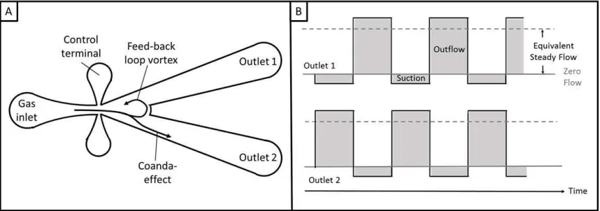
diversion between two identical channels (8, 15), as described in Figure 1. This switching results in a pulsed flow in each of the outlet channels, alternating between full forward flow, and very slight backflow. The flow in the forward regime bears similarity to laminar flow, whereas the slight backflow regime more closely resembles turbulence (16). This effect can be observed even in extremely small channel diameters and causes a disruptive effect which interrupts the formation of a boundary layer of stagnant gas flow along flow field chamber walls. While conventional oscillators require high flow rates on the order of 50-80 L/min, for this particular work we are utilising a jet diversion bistable fluidic oscillator with low onset (Desai-Zimmerman Fluidic Oscillator (DZFO), Perlemax Ltd., UK). This device is capable of producing an oscillatory flow at low onset flow rates of as low as 50 ml/min, which is necessary for operation with lab scale SOCs.
Figure 1. (A) cross-section of a fluidic oscillator showing the flow channels. Compressed gas enters through the gas inlet and flows to the middle chamber where, due to the Coanda effect, the flow “sticks” to the walls of one of the channels. This creates a feed-back loop vortex in the middle chamber which feeds feed-back through one of the control terminals, creating a pressure wave which then switches the direction of the flow. (B) Approximate change in flow velocities with time for the two outlets of a typical jet diversion bistable fluidic oscillator.
Test Rig Development
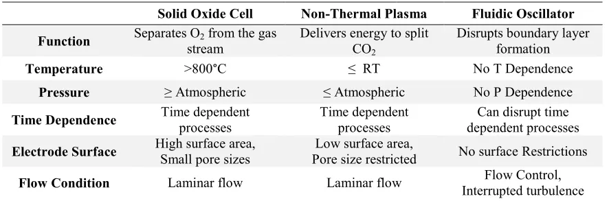
[image:4.612.93.522.234.385.2]TABLE I. Comparison of Standard Operating Conditions
Solid Oxide Cell Non-Thermal Plasma Fluidic Oscillator Function Separates O2 from the gas
stream Delivers energy to split CO2
Disrupts boundary layer formation
Temperature >800°C ≤ RT No T Dependence
Pressure ≥ Atmospheric ≤ Atmospheric No P Dependence
Time Dependence Time dependent processes Time dependent processes dependent processes Can disrupt time
Electrode Surface High surface area, Small pore sizes Pore size restricted Low surface area, No surface Restrictions
Flow Condition Laminar flow Laminar flow Interrupted turbulence Flow Control,
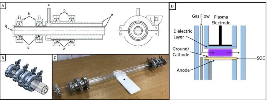
Visual confirmation is the easiest method of determining successful plasma generation and requires a bespoke furnace which allows a sufficiently large field of vision to monitor the active area. Additionally, having visual access to the device and reaction zone allows for the implementation of a variety of spectroscopic methods such as IR (17, 18, 19) and Raman spectroscopy (18, 20, 21, 22) in order to determine gas composition, materials composition, and adsorbed species in-operando. For these reasons, the reactor has been largely constructed from quartz tubing. Quartz is frequently used as a dielectric material in plasma reactors, is electrically insulating, and has a very low thermal expansion coefficient which allows us to work at high temperatures without risk of thermal failures. Additionally, a low thermal expansion coefficient also introduces little risk of important geometric factors, such as the gap distance between the SOC and the plasma electrode, changing with temperature.
Figure 2. (A) Engineering drawing of the test rig used in this work. The design features (a) a customisable end cap to allow for flexibility in experimental inputs, (b) KF type flanges with (d) viton o-rings to hold the (e) quartz tubing in place and keep the chambers gas tight, and (c) gas inlets for the outer chamber. (B) Simulated image of the clamping system. (C) Photograph of the completed test rig. (D) Schematic of the plasma/SOC reaction configuration used.
Results and Conclusions
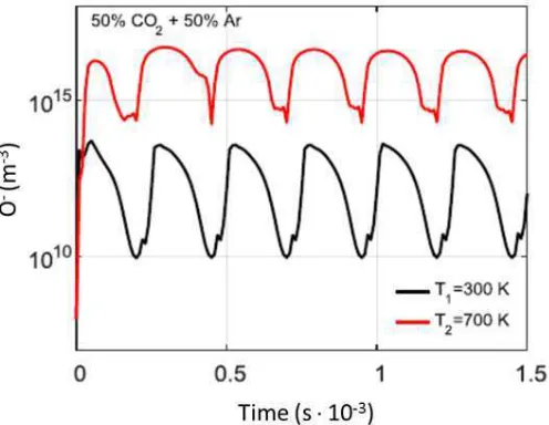
A preliminary DBD (Dielectric Barrier Discharge) plasma simulation was run to estimate the likely effects of temperature on the formation ofions relevant to solid oxide fuel cells in a 50% CO2 + 50% argon plasma. The model comprises equations for electric
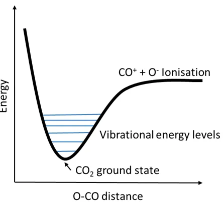
field strength, movement of charged particles in response to the electric field, particle diffusion, and gain and loss of species particles from reactions (23, 24). It is solved in 1D geometry and at the boundaries to simulate the reaction rates and species concentrations over time at each point along a line between two electrodes in a homogeneous glow discharge plasma, as shown in Figure 3. The plasma chemical reaction rate coefficient data was selected according to methods laid out in the literature (25, 26). Preliminary simulated results show a significant increase in the conductivity of the plasma due to greater numbers of charged particles as a consequence of greater gas density. Increased concentrations of oxygen ions at higher temperatures also serve to illustrate this, as shown in Figure 4. These simulated results will require experimental verification, but the results appear to be promising. It is also reasonable to assume that higher temperatures result in higher vibrational energy levels in the CO2 molecules, which effectively lowers
[image:6.612.92.522.53.214.2]Figure 3. Geometry of a DBD reactor. The dashed line shows the 1D representative geometry used for our plasma model.
Figure 4. Spatially averaged concentration of O- against time in the simulated plasma
[image:7.612.135.480.55.204.2] [image:7.612.176.424.274.466.2]Figure 5. Lennard-Jones potentials of the CO bond in the CO2 molecule. Each
successively higher vibrational excitation state reduces the energy barrier to ionisation.
Preliminary SOEC experimental results show performance improvement with the addition of oscillating gas flow, as shown in Figure 6, with the magnitude of improvement in polarization resistance being dependent on operating conditions such as gas composition and applied current/potential. Improvements are limited to the low and mid frequency range which indicates that mass transport losses have been greatly reduced and some improvement due to increased reactant availability at reaction sites is occuring. The effect of an oscillating fuel gas stream is promising and further research to understand the impact of this effect is underway.
Figure 6. Example nyquist plots of a SOC run under electrolysis conditions. A significant decrease in polarisation resistance is noted in low to mid-frequency regimes when operated under oscillating gas flow using the DZFO.
Acknowledgments
[image:8.612.197.419.53.262.2] [image:8.612.174.439.473.578.2]References
1. International Energy Agency, Energy Technology Perspectives 2017 (ETP 2017), (2017)
2. P. G. Levi and J. M. Cullen, Environmental Science and Technology, 53, p.1725-1734, (2018)
3. D. Gielen, J. Newman, M. K. Patel, MRS Bulletin, 33, p. 471-477, (2008)
4. S. Singhal and K. Kendall, High-Temperature Solid Oxide Fuel Cells, Elsevier Advanced Technology, (2003)
5. C. Graves, S. D. Ebbesen, M. Mogensen, and K. S. Lackner, Renewable and Sustainable Energy Reviews, 15, p.1-23, (2011)
6. T. Kozák and A. Bogaerts, Plasma Sources Science and Technology, 23(4), (2014)
7. W. B. J. Zimmerman, Microfluidics: History, Theory, and Applications, Springer-Verlag Wien, (2006)
8. W. B. Zimmerman, B. N. Hewakandamby, V. Tesař, H. C. H. Bandulasena, and O. A. Omotowa, Food and Bioproducts Processing, 87(3), p. 215-227, (2009) 9. I. G. Koo and W. M. Lee, Electrochem. Comm., 9, p. 2325-2329 (2007)
10.M. A. Capelli and W. Kim, Plasma Activated Fuel Cells in Global Climate and Energy Project (2007)
11.M. S. Lee, I. G. Koo, J. H. Kim, and W. M. Lee, International Journal of Hydrogen Energy, 34, p.40-47, (2009)
12.Y. Tagawa, S. Mori, M. Suzuki, I. Yamanaka, T. Obara, R. Junichi, and Y. Kato,
Kagaku Kogaku Ronbunshu, 37, p. 114-119, (2011)
13.S. Mori, N. Matsuura, L. L. Tun, and M. Suzuki, Plasma Chemistry and Plasma Processing, 36, p. 231-239, (2016)
14.V. Tesař, Pressure-Driven Microfluidics, Artech House, (2007)
15.V. Tesař and H. Bandalusena, Experiments in Fluids, 50, p.1225-1233, (2011) 16.V. Tesař, C. H. Hung, and W. B. Zimmerman, Sensors and Actuators A: Physical,
125, p.159-169, (2006)
17.D. J. Cumming, C. Tumilson, S. F. R. Taylor, S. Chansai, A. V. Call, J. Jacquemin, C. Hardacre, and R. H. Elder, Faraday Discussions, 182, p. 97-111, (2015)
18.N. Shi, Y. Xie, D. Huan, Y. Yang,S. Xue, Z. Qi, Y. Pan, R. Peng, C. Xia, and Y. Lu, Journal of Materials Chemistry A, 7, p. 4855- 4864, (2019)
19.M. Chlipala, P. Blaszczak, S.F. Wang, P. Jasinski, B. Bochentyn, International Journal of Hydrogen Energy, 26, p.13864-13874, (2019)
20.J. Manerova, A. V. Call, D. C. Sinclair, and R. H. Elder, ECS Transactions, 68(1), p.2083-2092, (2015)
21.B. C. Eigenbrodt and R. A. Walker, Spectroscopy, 29 (12), p. 24-30, (2014) 22.K. W. Reeping, J. M. Bohn, and R. A. Walker, Journal of Power Sources, 372, p.
188-195, (2017)
23.J. P. Boeuf, Phys. Rev. A, 36, p. 2782-2792, (1987)
24. A. A. Kulikovsky, J. Comput. Phys, 119, p.149-155, (1995)
25.C. Soria, F. Pontiga, and A. Castellanos, Plasma Sources Science and Technology,
13, p.95-107, (2004)